Note: Descriptions are shown in the official language in which they were submitted.
CA 02747450 2011-07-28
1
MACHINE FOR PACKAGING ARTICLES INSIDE CONTAINERS
The present invention relates to a machine for
packaging articles inside containers.
More particularly, the machine according to the
present invention is of the type comprising at
least one conveyor provided with a longitudinally
movable transporting section for feeding the
articles in a given direction and along a given
conveying path; a station for loading the articles
onto the transporting section; sensor means
arranged along the conveying path for detecting at
least the position of each article on the
transporting section; at least one robot arranged
along the conveying path; control means connected
to said sensor means and to said robot for
imparting to the robot commands for picking up
single articles from the transporting section and
transferring each picked-up article inside a
container.
A machine of this type is known, for example, from
European patent EP 0856465 Bl in the name of
Gerhard Schubert GmbH. In this machine, the
articles are loaded in bulk onto the operative
transporting section of a flat conveyor belt.
CA 02747450 2011-07-28
2
Downstream of the loading station the position and
direction of each article on the conveyor belt are
then detected so that subsequently a robot,
arranged along the conveying path downstream of the
detection station, is able to pick up each article
and then transfer it inside a container.
In a machine of this type, round articles, when
resting on the conveyor belt with their convex
surface, may start to roll in an undesirable manner
on the belt between the moment when their position
and direction are detected and the moment when they
must be gripped by the robot. As a result the robot
may not grip an article correctly or fail to grip
it all.
The object of the present invention is to provide a
machine for packaging articles inside containers
which does not have the abovementioned drawback.
According to the present invention a machine for
packaging articles inside containers is provided,
said machine comprising the characteristic features
present in one or more of the accompanying claims.
The technical features of the invention may be
clearly determined from the contents of the
accompanying claims and the advantages thereof will
emerge more clearly from the detailed description
CA 02747450 2011-07-28
3
which follows, with reference to the accompanying
drawings which illustrate a purely exemplary and
non-limiting embodiment thereof, where:
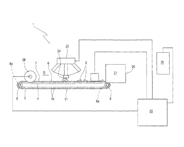
- Figure 1 shows schematically a front view,
partially in block form, of a machine for packaging
articles inside containers, provided in accordance
with the present invention;
- Figure 2 shows schematically a perspective view
of part of the machine shown in Figure 1;
- Figure 3 shows a perspective view of a portion of
a link conveyor forming part of the machine shown
in Figure 1;
- Figures 3a and 3b show a perspective view, from
above and below, respectively, of a section of the
conveyor shown in Figure 3;
- Figures 4a,4d relate to respective variants,
shown in cross-section, of the links of the
conveyor according to Figure 3.
In Figures 1 and 2, the reference number 1 denotes
in its entirety a machine for packaging articles 2
inside containers 3.
The articles 2 are preferably, but not exclusively,
food products. In this example the articles 2
consist of ice-cream cones 2 with a long, more
precisely conical, shape and a main longitudinal
CA 02747450 2011-07-28
4
axis 4 of extension.
The containers 3 are preferably, but not
exclusively, cardboard boxes 3.
The articles 2 are packaged, preferably but not
exclusively, in orderly groups 5 inside respective
containers 3.
In the example shown, the machine 1 is suitable for
performing automatic packaging of ice-cream cones 2
inside cardboard boxes 3 inside each of which a
group 5 of cones 2 is arranged in an orderly
manner.
According to a preferred mode of packaging in one
or two layers, the cones 2 alongside each other
within each layer are arranged in a direction
rotated through 1800 with respect to each other. In
the case of more than one layer, the vertically
aligned cones 2 of two superimposed layers are
arranged in a direction rotated through 180 with
respect to each other.
In both cases, the cones 2 are inserted in an
orderly and predetermined manner inside the box 3
so as to fill the box 3 wasting as little space as
possible.
The machine comprises at least one conveyor 6 which
is provided with a longitudinally movable
CA 02747450 2011-07-28
transporting section 7 for feeding the articles 2
in a given direction D and along a given
rectilinear conveying path P.
The conveyor 6 comprises at least two pulleys 8
5 with a horizontal axis 8a, at least one of which is
a driving pulley, and a chain 9 with links 10 wound
endlessly around the pulleys 8.
In the example shown the pulleys 8 are two in
number and arranged at the same height.
Between the two pulleys 8, the chain 9 defines, at
the top, the said transporting section 7 and, at
the bottom, a return section 11.
The transporting section 7 is horizontal.
Preferably, the return section 11 is also
horizontal.
The links 10 are preferably made of plastic.
The links 10 are hinged with each other along a
bottom wall 12 thereof by means of respective
cylindrical hinges 13 parallel to the axis 8a of
the pulleys 8 (Figures 3a and 3b).
In this way the links 10 are able to rotate
relative to each other, opening out in fan fashion,
along the winding arc around the pulleys 8, but are
arranged alongside, in contact with each other,
along the sections 7 and 11. More precisely, along
CA 02747450 2011-07-28
6
the sections 7 and 11 the adjacent links 10 have
their outer walls 14, i.e. the walls which support
the product 2 and are situated opposite to the
bottom walls 12, arranged alongside each other so
as to form a substantially continuous surface.
On the transporting section 7, each link 10 of the
chain 9 defines a respective basic portion 15 of
the bottom 16 of the transporting section 7 itself.
Two side shoulders 17, which are flared relative to
each other, project from the portion 15 and define
with the bottom portion 15 the said outer wall 14.
On the transporting section 7, the shoulders 17 of
the adjacent links 10 define, with a substantially
continuous surface, two side walls 18 of the
transporting section 7 itself.
The side walls 18 delimit transversely the
transporting section 7, are parallel to each other
and movable in the conveying direction D and
mutually converge towards the bottom 16 of the
transporting section 7, transversely relative to
the conveying direction D.
The side walls 18 extend with a continuous surface
from the bottom 16 of the transporting section 7
and define transversely a groove 19 or concavity 19
for receiving the articles 2.
CA 02747450 2011-07-28
7
The groove 19 and the links 10 have, in cross-
section, a substantially triangular shape, as
illustrated more clearly in Figure 4c.
Figure 4d shows a variation of embodiment of the
cross-section of the links 10 and the groove 19
shown in Figure 4c. In this case, the groove 19 and
the links 10 have, in cross-section, a
substantially triangular shape which is
asymmetrical instead of symmetrical.
According to a further variant, shown in Figure 4a,
the groove 19 and the links 10 have, in cross-
section, a substantially trapezoidal shape.
Figure 4b shows a variation of embodiment of the
cross-section of the links 10 and the groove 19
shown in Figure 4a. In this case, the groove 19 and
the links 10 have, in cross-section, a
substantially trapezoidal shape which is
asymmetrical instead of symmetrical.
The machine 1 also comprises a station 20 for
loading the articles 2 onto the transporting
section 7. The loading station 20 comprises a feed
unit 21 for loading the articles 2 one behind
another in a row onto the transporting section 7.
On the transporting section 7 the articles 2 may be
arranged at a constant interval or at a random
CA 02747450 2011-07-28
8
distance from each other along the row.
Once arranged on the conveyor 6, the articles 2 are
stably seated between the walls 18 one behind
another in the conveying direction D. In other
words, the side walls 18, by retaining the articles
2 inside the groove 19, act as elements for
stabilising the position and direction of each
article 2 with respect to the transporting section
7.
Generally, the articles 2 are varyingly spaced from
each other along the conveying path P and may be
arranged in the same direction or have, in an
alternating or random manner, a direction rotated
through 180 with respect to the other adjacent
article in the row.
The machine 1 also comprises sensor means 22
arranged along the conveying path P for detecting
at least the position of each article 2 on the
transporting section 7.
In the case where the articles 2 are all arranged
in the same direction on the transporting section
7, the sensor means 22 may comprise a simple
photocell; in the case where the articles 2 have,
in an alternating or random manner, a direction
rotated through 180 with respect to the other
CA 02747450 2011-07-28
9
adjacent article in the row, the sensor means 22
preferably comprise a telecamera able to detect
both the position and the direction of each article
2.
The machine 1 also comprises at least one robot 23
arranged along the conveying path P. The robot 23
comprises a movable gripping head 24 which has a
component of movement directed along the
transporting section 7 parallel to the conveying
direction D.
The gripping head 24 comprises preferably at least
two gripping jaws which are coordinated with the
sucking action of a suction mouth. The gripping
head 24 is also motor-driven so as to be able to
rotate about an axis perpendicular to the conveying
plane of the articles 2, so as to be able to pick
up the articles 2 independently of their direction
within the groove 19.
The machine 1 also comprises control means 25 which
are connected to the sensor means 22 and to the
robot 23 as well as to an encoder 26 of the
conveyor 6 and are intended to impart to the robot
23 commands for picking up single articles 2 from
the transporting section 7 and transferring each
picked-up article 2 inside a container 3.
CA 02747450 2011-07-28
The encoder 26 provides information as to the
position of the transporting section 7 and,
independently of the speed of the latter, allows
one to determine the position of each article 2 on
5 the section 7 and monitor the article 2 during
gripping thereof.
The control means 25 are connected via an Ethernet
or other type of network to a central management
unit 30.
10 In accordance with that shown in Figure 2, the
containers 3 are fed in succession towards the
operating area of the robot 23 by means of a
conveyor 27.
The conveyor 27 comprises two pulleys (not shown)
with a horizontal axis, at least one of which is
the driving pulley, and a belt 28 wound endlessly
around the pulleys.
Between the two pulleys, the belt 28 defines, at
the top, a transporting section 29 and, at the
bottom, a return section (not shown).
The transporting section 29 is horizontal and
extends parallel to the transporting section 7.
Preferably, the sections 7 and 29 are arranged at
the same height.
The sections 7 and 29 may be moved in the same
CA 02747450 2011-07-28
11
direction or in a contrary sense, i.e. in opposite
directions.
In the case where the articles 2 must be packaged
in orderly groups inside respective containers 3,
the control means 25 are programmed to impart to
the robot 23 commands for picking up single
articles 2 from the transporting section 7 and
transferring each picked-up article 2 into the same
container 3 until a predetermined number n of
inserted articles 2, defining a group, is reached
inside the said container 3.
During operation, the articles 2, although resting
on the transporting section 7 with a convex surface
thereof, more specifically with their conical side
surface, are unable to roll in an undesirable
manner on the transporting section 7 between the
moment when their position and, if applicable,
direction are detected and the moment when they
must be gripped by the robot 23. This is ensured by
the fact that each article 2 is retained, with
contact, between the shoulders 17 of the links 10,
or in other words between the side walls 18, in a
stable fixed position on the transporting section
7. In particular, each article 2 is stably seated
inside the groove 19 with its longitudinal axis 4
CA 02747450 2011-07-28
12
aligned with the conveying direction D.
It is evident that, in the case where the sensor
means 22 comprise a telecamera, the latter may
provide the control means 25 also with information
relating to the form and/or quality and/or type of
article 2. In the specific case of the example
shown, the control means 25 may impart to the robot
23 a discard command in the case where the cone 2
to be picked up has been detected as being
defective or may impart to the robot 23 a command
for performing transfer to different containers
depending on the flavour of the cone 2, in the case
where the conveyor 6 is supplied with cones 2 of
varying flavours.
It should also be pointed out that the side walls
18 described above as forming an integral part of
the transporting section 7 of the conveyor 6 could
also be formed, in a technically equivalent manner,
as separate elements provided that they are movable
in synchronism with the transporting section 7. For
example, each wall 18 could be defined by a belt
wound around respective inclined-axis pulleys and
driven in synchronism with a conveyor belt defining
the abovementioned transporting section.
The invention may obviously be implemented on an
CA 02747450 2011-07-28
13
industrial level; moreover it may be subject to
numerous modifications and variations all falling
within the scope of the inventive idea; all the
details may be replaced moreover by technically
equivalent elements.