Note: Descriptions are shown in the official language in which they were submitted.
CA 02747471 2011-07-28
1
A CONTAINER
Technical Field
The present invention relates to containers and more particularly but not
exclusively to containers to receive liquid fuel.
s Background of the Invention
When mixing fuel, typically for two-stroke engines, a container is used into
which the fuel is delivered. A lubricant such as oil is mixed with the fuel in
a
predetermined volumetric ratio. As an example, the volumetric relationship of
fuel to oil
may be 50:1.
Jo Typically the lubricant is measured in a measuring cup or other hollow
measuring device. The measuring lubricant is delivered to the interior of a
container and
mixed with the fuel.
A disadvantage of the above discussed container is that it is necessary to
provide
a separate measuring cup. A further disadvantage is that should no measuring
cup be
15 available, frequently a user will approximate the volume of lubricant to be
added to the
fuel. If this is incorrectly estimated damage to the two-stroke engine may
occur.
Disclosed in International PCT/AU2007/001791 is a container for the delivery
of
liquids. In particular this International application relates to watering
cans. It does not
provide information relating to a container for the transportation of fuels.
20 Disclosed in USA Patent 5447245 is a container within which fuel and oil is
to
be mixed for the purposes of delivering the mixture to a two-stroke engine.
The container
has two passages via which the liquids are delivered to the interior of the
container. One
passage delivers the oil to a metering chamber, while the other passage
delivers the fuel to
the main body of the container. Joining the chambers is a throat. However the
object of
25 the container of the specification is to inhibit liquid passing through the
throat.
Accordingly a disadvantage of the container is that the throat is relatively
small. A still
further disadvantage is that the passage that delivers liquid to the measuring
chamber is
not intended to provide for the delivery of the fuel to the other main
chamber.
Object of the Invention
30 It is the object of the present invention to overcome or substantially
ameliorate at
least one of the above disadvantages.
CA 02747471 2011-07-28
2
Summary of the Invention
There is disclosed herein a container to receive a liquid, the container
including:
a hollow body to receive the liquid, the body having a bottom wall, a side
wall,
the side wall having at least a part that is light transmissive so that a user
can determine
the liquid depth adjacent the wall, a partition wall extending upwardly
relative to the
bottom, and dividing the container internally into a major sub-chamber and a
measuring
sub-chamber, the measuring sub-chamber being adjacent the side wall and in
communication with the main sub-chamber; and
a spout providing a passage via which liquid is delivered to the chambers, the
to spout being above the sub-chambers so as to provide for delivery of liquid
from the spout
to the measuring sub-chambers, and wherein the passage is the only passage via
which
liquid is delivered to and from the sub-chambers.
Preferably, the container includes a cap to engage the spout to close the
spout.
Preferably, the container includes an air vent.
Preferably, said wall is provided with graduations to aid a user in estimating
the
volume of liquid in the measuring sub-chamber.
Preferably, the container has a top wall, and a handle attached to the top
wall so
as to be above the major sub-chamber.
Preferably, the sub-chambers are connected by a throat, said throat having a
width and height, said main sub-chamber has a height with the throat height
being at least
a half of the main sub-chamber height.
Preferably, the throat height is at a quarter of the main sub-chamber height.
Preferably, said partition wall has an upper extremity, said side wall is a
first side
wall, and the container includes a pair of spaced further side walls between
which the first
wall extends, with said extremity extending between the further side walls.
Preferably, said passage extends longitudinally toward said extremity, and is
inclined to the horizontal by an acute angle.
Brief Description of the Drawings
A preferred form of the present invention will now be described by way of
example with reference to the accompanying drawings wherein:
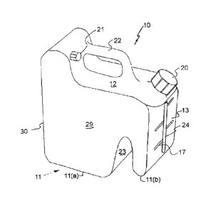
Figure 1 is a schematic isometric view of a container to receive liquid fuel;
CA 02747471 2011-07-28
3
Figure 2 is a schematic sectioned side elevation of portion of the container
of
Figure 1;
Figure 3 is a schematic isometric view of a modification of the container of
Figures 1 and 2;
Figure 4 is a schematic planned sectioned view of the container of Figure 3;
and
Figure 5 is a schematic sectioned side elevation of the container of Figure 3.
Detailed Description of the Preferred Embodiments
In Figures 1 and 2 of the accompanying drawings there is schematically
depicted
a container 10 to receive liquid fuel. The container 10 is moulded from
plastics material.
io Typically the container 10 would be used to mix a liquid fuel with a
lubricant. For
example, if the container 10 was to provide petrol for a two-stroke engine,
the container
would receive petrol and a volume of oil to be mixed therewith.
The container 10 includes a bottom wall 11 and a top wall 12 as well as a side
walls 13, 29 and 30. The walls 11, 12 and 13 at least partly enclose a
container chamber
14. The chamber 14 includes a major sub-chamber 15 and a measuring sub-chamber
16.
The sub-chamber 16 is adjacent the wall 13.
The wall 13 provides for the transmission of light through at least a part of
the
wall 13 so that the level of liquid in the measuring sub-chamber 16 may be
determined.
Preferably, the side wall 13 has a vertical transparent strip 24 through which
the liquid
can be seen. Typically the wall 13 would be provided with graduations 17 to
assist the
user in determining the volume of, for example, oil in the measuring sub-
chamber 16.
Joining the top wall 12 and side wall 13 is an inclined wall 18 that provides
a
spout 19. The spout 19 is located above the sub-chamber 16 so that oil may be
delivered
directly from the spout 19 into the sub-chamber 16 so that the volume of oil
may be
measured. Thereafter petrol is added to the sub-chambers 15 and 16 and mixed
with the
oil contained in the sub-chamber 16.
The sub-chambers 15 and 16 are connected so that the petrol and oil can be
mixed.
The spout 19 is provided with a cap 20, while the container 10 may also be
provided with a vent (closable) 21.
For ease of handling, a handle 22 is provided and is attached to the top wall
12.
CA 02747471 2011-07-28
4
The sub-chambers 15 and 16 are partitioned by means of a dividing wall 23 that
extends upwardly from the bottom wall 11.
The chamber 14 is essentially sealingly enclosed when the vent 21 is closed
and
the cap 20 sealingly engaged with the spout 19.
The wall 23 has an upper extremity 26 that extends transversely across the
interior of the container, and preferably between the internal surfaces of the
walls 29. The
upper extremity 26 is also spaced from the top wall 12 by a height 25 so as to
provide a
throat 28.
The spout 19 provides a passage 27 with a longitudinal axis 32, with the
passage
27 and longitudinal axis 32 generally directed at the upper extremity 26 so
that when
liquid is being delivered to the interior of the container with a reasonable
flow rate, the
liquid is distributed between the chambers 15 and 16. However when a liquid is
delivered
to the interior at a slower flow rate, the liquid is delivered to the chamber
16.
Preferably, the height 25 is at least 50% of the height 31. More preferably
the
height 25 is at least or approximately 25% of the height 31.
The bottom wall 11 includes a bottom wall portion 11(a) and a bottom wall
portion 11(b), with at least the bottom wall portion 11(a) providing a surface
upon which
the container rests.
In the embodiment of Figures 3 to 5, the wall 23 includes a web 33.
Accordingly
the wall 23 provides a pair of slots 34 that extend transversely inwardly from
the side
walls 29 to the central web 33.
Preferably, the transverse width 32 between in the internal surfaces of the
side
walls 29 is approximately equal the length of the upper extremity 26.