Note: Descriptions are shown in the official language in which they were submitted.
CA 02747506 2013-01-30
VISIBLE OPEN FOR SWITCHGEAR ASSEMBLY
BACKGROUND OF THE INVENTION
[0001] The present invention relates to electrical cable connectors, such as
loadbreak
connectors and deadbreak connectors. More particularly, aspects described
herein relate to an
electrical cable connector, such as a power cable elbow or T-connector
connected to electrical
switchgear assembly.
[0002] High and medium voltage switch assemblies may include sub-atmospheric
or
vacuum type circuit interrupters, switches, or circuit breakers for use in
electric power circuits
and systems. Insulated vacuum bottles switches in such systems typically do
not provide
means for visual inspection of the contacts to confirm whether they are open
(visible break) or
closed. Non-vacuum bottle type switches previously used were designed to
include contacts
in a large gas or oil filled cabinet that allowed a glass window to be
installed for viewing the
contacts. However, with vacuum type switches, there is typically provided no
means of
directly viewing contacts in the vacuum bottles since the bottles are made of
metal and
ceramic non-transparent materials.
[0003] Typically, conventional insulated switches using vacuum technology are
sealed
inside the vacuum bottle and hidden from view. The voltage source and the load
are
connected to the switch, but the switch contacts are not visible. The only
means for
determining the status of the switch contacts is the position of a switch
handle associated with
the switch. If the linkage between the handle and the switch contacts is
inoperative or
defective, there is no positive indication that allows the operating personnel
to accurately
determine the position of the contacts. This can result in false readings,
which can be very
dangerous to anyone operating the switch or working on the lines/equipment.
SUMMARY OF THE INVENTION
[0004] In accordance with one aspect of the present invention, there is
provided an
electrical connector assembly, comprising a connector body having a conductor
receiving end,
a connector end, a linking assembly connecting the conductor receiving end to
the connector
end, and a visible open port positioned in the connector body for viewing at
least a portion of
- 1 -
CA 02747506 2013-01-30
the linking assembly, wherein the linking assembly comprises a rearward
conductive end
conductively coupled to the conductor receiving end, a flexible conductor
conductively
coupled to the connector end, and a linking pin coupled to the flexible
conductor and movable
between a first position and a second position, wherein the first position
maintains the
conductor receiving end electrically isolated from the connector end, and the
second
10004.11 In accordance with another aspect of the present invention, there is
provided a
power cable elbow assembly, comprising a connector body having an axial bore
therethrough,
wherein the connector body comprises a conductor receiving end for receiving a
cable, a
connector end projecting substantially perpendicularly from the connector body
at an end
distal from the conductor receiving end, a linking assembly connecting the
conductor
receiving end to the connector end, and a viewing port positioned on the
connector body for
viewing at least a portion of the linking assembly, wherein the linking
assembly comprises a
linking pin moveable between a first position and a second position, wherein
the first position
maintains the conductor receiving end electrically isolated from the connector
end, and the
second position conductively couples the conductor receiving end to the
connector end, and
wherein the viewing port is configured to enable viewing of at least a portion
of the linking
pin.
- 1 a -
CA 02747506 2011-07-27
BRIEF DESCRIPTION OF THE DRAWINGS
[0005] Figure 1A is a schematic cross-sectional diagram illustrating an
electrical connector
consistent with implementations described herein in a de-energized state;
[0006] Figure 1B is a top view diagram of the electrical connector of Fig. lA
in the de-
energized state;
[0007] Figure 2A is a schematic cross-sectional diagram illustrating an
electrical connector
consistent with implementations described herein in an energized state; and
[0008] Figure 2B is a top view diagram of the electrical connector of Fig. 2A
in the
energized state.
DETAILED DESCRIPTION OF THE PREFERRED EMBODIMENTS
[0009] The following detailed description refers to the accompanying drawings.
The same
reference numbers in different drawings may identify the same or similar
elements.
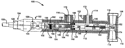
[0010] Figs. 1A and 1B are a schematic cross-sectional diagram and top view,
respectively,
illustrating a power cable elbow connector 100 configured in a manner
consistent with
implementations described herein in a de-energized state. As shown in Fig. 1A,
power cable
elbow connector 100 may include a body portion 102, a conductor receiving end
104 for
receiving a power cable 106 therein, first and second T ends 108/110 distal
from conductor
receiving end 104 and that include openings for receiving a deadbreak
transformer bushing or
other high or medium voltage terminal, such as an insulating plug, or other
power equipment
(e.g., a tap, a grounding device, a voltage arrestor, a bushing, etc.), a
visible open linking
assembly 112, a link access opening 114, and a visible open port 116.
[0011] First T end 108 and second T end 110 may include a flange or elbow cuff
118
surrounding the open receiving end thereof. Body portion 102 may extend
substantially
axially and may include a bore extending therethrough. First and second T ends
108/110, link
access opening 114, and visible open port 116 may project substantially
perpendicularly from
body portion 102, as illustrated in Fig. 1A.
[0012] Power cable elbow connector 100 may include an electrically conductive
outer
shield 120 formed from, for example, a conductive or semi-conductive peroxide-
cured
synthetic rubber, such as EPDM (ethylene-propylene-dienemonomer). Within
shield 120,
- 2 -
CA 02747506 2011-07-27
power cable elbow connector 100 may include an insulative inner housing 122,
typically
molded from an insulative rubber or epoxy material. Within insulative inner
housing 122,
power cable elbow connector 100 may include a conductive or semi-conductive
insert 124 that
surrounds the connection portion of power cable 106 and visible open linking
assembly 112.
[0013] Conductor receiving end 104 of power cable elbow connector 100 may be
configured to receive power cable 106 therein. As shown in Fig. 1A, a forward
end of power
cable 106 may be prepared by connecting power cable 106 to a conductor spade
assembly
126. Conductor spade assembly 126 may include a modular configuration that
includes a
rearward sealing portion 128, a crimp connector portion 130, and a spade
portion 132.
[0014] Rearward sealing portion 128 may include an insulative material
surrounding a
portion of power cable 106 about an opening of conductor receiving end 104.
When
conductor spade assembly 126 is positioned within conductor receiving end 104
(e.g., within
insert 124), rearward sealing portion 128 may seal an opening of conductor
receiving end 104
about power cable 106.
[0015] Crimp connector portion 130 may include a substantially cylindrical
assembly
configured to receive a center conductor 134 of power cable 106 therein. Upon
insertion of
center conductor 134 therein, crimp connector portion 130 may be crimped onto
or otherwise
secured to center conductor 134 prior to insertion of power cable 106 into
conductor receiving
end 104.
[0016] Spade portion 132 may be conductively coupled to crimp connector
portion 130 and
may extend axially therefrom. In one implementation, spade portion 132 may
have
substantially planar upper and lower surfaces and may include a perpendicular
bore 136
extending therethrough.
[0017] As shown in Fig. 1A, visible open linking assembly 112 may be
configured to
enable conductive coupling of power cable 106 to T ends 108 and 110 when the
link is in an
energized state (as shown in Figs. 2A and 2B). As shown in Figs. 1A and 1B,
when visible
open linking assembly 112 is in an insulated or de-energized state, visible
open linking
assembly 112 is configured to insulate T-ends 108 and 110 from power cable
106.
[0018] In one embodiment, visible open linking assembly 112 may include a
housing 138, a
rearward spade assembly 140, a cavity142, a linking pin 144, a rack and pinion
housing 145, a
- 3 -
CA 02747506 2011-07-27
forward insulative portion 146, a conductive rack and pinion assembly 148, a
flexible
conductor 150, and a forward spade portion 152.
[0019] Housing portion 138 may be formed of, for example, insulative rubber or
epoxy
material and may be substantially cylindrical in one implementation. Housing
portion 138
may by sized to fit within insert 122 in connector 100.
[0020] Rearward spade assembly 140 may include a conductive insert 154
maintained
within housing portion 138 and a rearward spade 156. Conductive insert 154 may
be formed
of a conductive material, such as copper or aluminum and may be secured within
a rearward
portion of housing portion 138. As shown in Fig. 1A, conductive insert 154 may
include a
substantially cylindrical cavity 158 formed axially in a forward portion
thereof. As described
below, cylindrical cavity 158 is configured to receive a portion of linking
pin 144 when
linking pin 144 is in an energized state. In one implementation, a portion of
rearward spade
assembly 140 proximate to cylindrical cavity 158 may have a decreased outside
diameter with
respect to a rearward portion of rearward spade assembly 140. As shown in Fig.
1A, this
configuration may allow cavity 142 to surround the portion of rearward spade
assembly 140
proximate to cylindrical cavity 158, thereby increasing the isolation of
conductive rack and
pinion assembly 148 from rearward spade assembly 140 when connector 100 is in
an isolated
or de-energized state.
[0021] Rearward spade 156 may project axially from housing portion 138 in a
rearward
direction (e.g., toward power cable 106). In one implementation, spade 156 may
be formed
integrally with conductive insert 154 in a one-piece construction. Similar to
spade portion 132
described above, rearward spade 156 may also have substantially planar upper
and lower
surfaces and may include a perpendicular bore 160 extending therethrough. As
shown in Fig.
1A, the position of rearward spade 156 may be offset with respect to spade
portion 132,
thereby allowing perpendicular bore 160 in rearward spade 156 to align with
perpendicular
bore 136 in spade portion 132. Spade portion 132 may be securely fastened to
rearward spade
156, such as via a stud or bolt 162 threaded into bores 136/160 in spade
portions 132/156,
respectively.
[0022] Cavity 142 may be formed around rearward spade assembly 140 and may
form an
air gap between conductive rearward spade assembly 140 and forward insulative
portion 146.
- 4 -
CA 02747506 2011-07-27
,
As shown in Fig. 1A, cavity 142 may extend axially forward of rearward spade
assembly 140
within housing 138 such that at least a portion of cavity 142 extends past
visible open port 116
in shield 120. In addition, cavity 142 may be configured to receive at least a
portion of
linking pin 144, when linking pin 144 extends between conductive rack and
pinion assembly
148 and rearward spade assembly 140.
[0023] Linking pin 144 may include an insulative tip portion 164 and a
conductive portion
166 and may be secured to rack and pinion assembly 148 at an end proximate to
conductive
portion 166. Linking pin 144 may through cavity 142 and into cylindrical
cavity 158 in
rearward spade assembly 140. Linking pin 144 may be movable between an
isolated or de-
energized position (shown in Figs. lA and 1B) an energized position (shown in
Figs. 2A and
2B). In the isolated position, insulative tip portion 164 may be positioned
within cylindrical
cavity 158 and cavity 142 to bridge rearward spade assembly 140 and conductive
rack and
pinion assembly 148, effectively isolating cable 106 from T ends 108/110.
[0024] In the energized state, linking pin 144 may be moved (e.g., drawn
further into cavity
158 in rearward spade assembly 140), such that conductive portion 166 of
linking pin 144
conductively couples rearward spade assembly 140 and conductive rack and
pinion assembly
148. This allows for conductive linking between cable 106 and first and second
T ends
108/110.
[0025] At its forward end, linking pin 144 is conductively coupled to
conductive rack and
pinion assembly 148 within rack and pinion housing 145. In one embodiment,
rack and
pinion housing 145 may be formed of a conductive or semi-conductive material
and may form
a cavity that substantially surrounds rack and pinion assembly 148 and allows
movement of
rack and pinion assembly 148 therein.
[0026] Forward insulative portion 146 may be formed between rack and pinion
housing 145
and cavity 142. As shown in Figs. 1A and 1B, forward insulative portion 146
may include a
bore 168 therethrough through which at least a portion of linking pin 144 may
travel.
[0027] Conductive rack and pinion assembly 148 may be coupled to a forward end
of
linking pin 144 and may include a rack portion 170 aligned with link access
opening 114. As
shown in Fig. 1A, a suitable tool (e.g., ratchet 172) may be extended through
link access
opening 114 and engage rack portion 170. By turning ratchet 172, rack portion
170 may be
- 5 -
CA 02747506 2011-07-27
axially translated or moved forwardly or rearwardly, thereby moving connector
100 between
the isolated state and the energized state. Upon completion of the
translation, tool 172 may be
removed and an insulating plug 200 (shown in Fig. 2A) may be installed within
link access
opening 114. In some implementations, flexible conductor 150 may be expand
from a
compressed or relaxed configuration to a taught or stretched upon
transitioning from the
isolated state to the energized state.
[0028] Although an external tool 172 is shown in Fig. lA and described above,
in other
implementations, manipulation of rack portion 170 may be provided by an
integrated
engagement assembly. For example, a gear similar to the end of tool 172 may be
permanently
mounted within connector body portion 102 and provided with a knob or other
suitable user
engagement element. In still other implementations, the gear may be
electrically moved via a
small motor (e.g., a servo motor) mounted within body portion 102.
[0029] Flexible conductor 150 may be secured to the forward end of rack
portion 170 and
may conductively couple rack portion 170 to forward spade portion 152. In one
implementation flexible conductor 150 may be formed of a braided conductor
(e.g., copper), a
bellow, etc. Similar to spade portion 132 described above, forward spade
portion 152 may
extend axially from rack and pinion assembly 148 in a forward direction (e.g.,
toward T-ends
108/110). Forward spade portion 152 may also have substantially planar upper
and lower
surfaces and may include a perpendicular bore 174 extending therethrough. As
shown in Fig.
1A, forward spade portion 152 may project into a space between first T end 108
and second T
end 110. Once forward spade assembly 152 is properly seated within connector
100, bore 174
may allow a stud or other element associated with first T end 108 to
conductively engage
spade assembly 152 and/or a device connected to second T end 110.
[0030] Consistent with implementations described herein, insulative body 138
in visible
open linking assembly 112 may include a visible open area 176 aligned with
visible open port
116 in connector 100. In one implementation, visible open area 176 and visible
open port 116
formed in connector shield 120, insulative inner housing 122, and semi-
conductive insert 124,
may be formed of a transparent or substantially transparent insulating
material, such as glass,
plastic, etc. In some implementations, visible open port 116 and/or visible
open area 176 may
- 6 -
CA 02747506 2011-07-27
be provided in only a portion of connector 100, as shown in Fig. 1B (e.g., as
a cylindrical or
rectangular window or port through connector 100).
[0031] By forming visible open area 176 and visible open port 116 of a
transparent
material, a technician or worker may be able to visually confirm that linking
pin 144 is in the
isolated or de-energized state. For example, in one implementation, insulated
tip portion 164
of linking pin 144 may be formed of a particular color, such as green. In such
an
implementation, insulated tip portion 164 may be provided in an area adjacent
to visible open
area 176 and visible open port 116 when the linking pin 144 is in the isolated
state, as shown
in Figs 1A and 1B. However, when the linking pin 144 is in the energized
state, as shown in
Figs 2A and 2B, insulated tip portion 164 is moved away from the viewing area
or visual
proximity with visible open area 176 and visible open port 116. That is, tip
portion 164 is not
visible via visible open port 116 when connector 100 is in the isolated state.
In another
embodiment, conductive portion 166 of linking pin 144 may be provided with a
second color,
such as red. A visible red portion 166 within visible open port 116 may
indicate that
connector 100 is in an energized condition.
[0032] By
providing an effective and safe mechanism for visibly identifying an open
break
in an electrical connector without requiring removal of switchgear components,
various
personnel may be more easily able to safely identify and confirm an isolated
or de-energized
condition in a switchgear assembly. More specifically, consistent with aspects
described
herein, personnel may be able to physically view the isolation element, and
not merely an
indicator of an open status, thereby more fully ensuring the personnel that
the equipment is, in
fact, de-energized. Furthermore, by providing the visible open on an elbow
connector
connected to the switchgear, existing or legacy switchgear may be easily
retrofitted and the
entire system may maintain a ground connection throughout operation.
[0033] The foregoing description of exemplary implementations provides
illustration and
description, but is not intended to be exhaustive or to limit the embodiments
described herein
to the precise form disclosed. Modifications and variations are possible in
light of the above
teachings or may be acquired from practice of the embodiments. For example,
implementations may also be used for other devices, such as other medium or
high voltage
- 7 -
CA 02747506 2013-01-30
switchgear equipment, such as any 15 kV, 25 kV, 35 kV, etc., equipment,
including both
deadbreak-class and loadbreak-class equipment.
[0034] For example, various features have been mainly described above with
respect to
elbow power connectors. In other implementations, other medium/high voltage
power
components may be configured to include the visible open port configuration
described above.
[0035] Although the invention has been described in detail above, it is
expressly understood
that it will be apparent to persons skilled in the relevant art that the
invention may be
modified. Various changes of form, design, or arrangement may be made to the
invention.
The scope of the claims should not be limited by the preferred embodiments set
forth in the
examples, but should be given the broadest interpretation consistent with the
description as a
whole.
[0036] No element, act, or instruction used in the description of the present
application
should be construed as critical or essential to the invention unless
explicitly described as such.
Also, as used herein, the article "a" is intended to include one or more
items. Further, the
phrase "based on" is intended to mean "based, at least in part, on" unless
explicitly stated
otherwise.
- 8 -