Note: Descriptions are shown in the official language in which they were submitted.
r .
CA 02747568 2011-06-17
WAVEFORM BEAM GUARDRAIL PLATE AND
WAVEFORM BEAM STEEL GUARDRAIL
FIELD OF THE INVENTION
[0001] The present invention relates to a vehicle anti-collision facility on a
road and a bridge,
particular to a single-wave beam guardrail plate and a single-wave beam steel
guardrail.
BACKGROUND OF THE INVENTION
[0002] With the rapid development of the road construction and the
transportation industry in
China, the traffic safety faces a grim situation. The anti-collision
guardrail, as a security facility,
plays an important role in protecting the traffic safety on roads and bridges.
[0003] Generally, the anti-collision guardrail mainly includes three types,
i.e., the rigid guardrail,
the semi-rigid guardrail and the flexible guardrail. Among them, the rigid
guardrail primarily
includes the concrete guardrail such as the New Jersey guardrail and the
combined guardrail. Such
a concrete guardrail has overlarge rigidity, so the abilities of cushioning
and absorbing vehicle
kinetic energy are weak. When the gravity center of a vehicle is relatively
high, the vehicle is
prone to turn over the concrete guardrail after it crashed against the
concrete guardrail; and when
the gravity center of a vehicle is relatively low, the vehicle is prone to
turn over laterally after it
crashed against the concrete guardrail. The semi-rigid guardrail primarily
includes the waveform
beam guardrail and the beam-column guardrail. The waveform beam guardrail
includes the
two-wave guardrail and the three-wave guardrail. Such a waveform beam
guardrail absorbs the
vehicle kinetic energy by the upward and downward deformations of the steel
plate, which results
in a large consumption of steel material and poor landscape effects. The beam-
column guardrail is
constituted of a plurality of parallel steel pipes in the shape of circle or
rectangle. The collision
grade of these beam-column guardrails is relatively low.
[0004] At present, the anti-collision guardrail used on roads and bridges in
China is designed and
provided for all vehicles, regardless of a big vehicle or a small vehicle. All
vehicles crash against
such guardrail having the same anti-collision grade when a collision occurs.
However, the
CA 02747568 2011-06-17
anti-collision guardrail for protecting small vehicles needs flexible design,
and the anti-collision
guardrail for protecting big vehicles needs rigid design. The semi-rigid anti-
collision guardrail has
a relatively low protection grade for big vehicles and has a relatively large
consumption of steel
material.
[0005] In fact, the anti-collision guardrail, as an important safety
protection facility, should have
a sufficient cushioning capability while stopping a vehicle out of control.
That is, the anti-collision
guardrail should have not only a sufficient anti-collision grade but also a
sufficient cushioning
capability, so as to gradually reduce the vehicle kinetic energy. When being
crashed by a small
vehicle, the anti-collision guardrail should stop or smoothly make the small
vehicle drive out at the
expected angle by use of the cushioning capability thereof. When being crashed
by a big vehicle,
the anti-collision guardrail should firstly cushion the big vehicle and then
stop or make the big
vehicle drive out at the expected angle, so that the big vehicle cannot pass
through or turn over the
guardrail. In addition, the anti-collision guardrail on roads in a city and
roads in a scenic zone
should produce a certain aesthetic effect.
SUMMARY OF THE INVENTION
[0006] In view of the above problems, the object of the present invention is
to provide a
single-wave beam guardrail plate and a single-wave beam steel guardrail, which
may achieve
advantages such as a high anti-collision grade, a strong cushioning capability
and a beautiful
appearance.
[0007] In order to achieve the object, the present invention adopts the
following technical
solutions. A single-wave beam guardrail plate includes a guardrail plate body
integrally formed by
rolling, and two energy-accumulating rings which have the same structure and
are symmetrically
disposed in the axial direction at an upper edge and a lower edge of the
guardrail plate body. The
cross section of the guardrail plate body is in the shape of arc. The two
energy-accumulating rings
are formed by the upper edge and the lower edge of the guardrail plate body
being curled inwardly
and helically toward a convex direction of the guardrail plate body,
respectively.
[0008] Further, a cross section of each of the two energy-accumulating rings
is of a pipe-in-pipe
structure in which a first steel pipe is inserted inside a second steel pipe
and connected with an
inner wall of the second steel pipe. The walls of the first steel pipe and the
second steel pipe have a
2
= CA 02747568 2014-03-10
a common section near the convex portion of the guardrail plate body.
[0009] Further, in the two energy-accumulating rings, a common tangent of an
outer circle of
the first steel pipe of the first energy-accumulating ring and an outer circle
of the first steel pipe
of the second energy-accumulating ring is perpendicular to a radius of the
guardrail plate body. A
common tangent of an outer circle of the second steel pipe of the first energy-
accumulating ring
and an outer circle of the second steel pipe of the second energy-accumulating
ring is
perpendicular to the radius of the guardrail plate body. A middle point of the
common tangent of
the outer circle of the second steel pipe of the first energy-accumulating
ring and the outer circle
of the second steel pipe of the second energy-accumulating ring coincides with
a middle point of
the arc of the guardrail plate body. A connection line between the center of
the inner circle or the
outer circle of the first steel pipe of the first energy-accumulating ring and
the center of the inner
circle or the outer circle of the first steel pipe of the second energy-
accumulating ring is
perpendicular to the radius of the guardrail plate body. A connection line
between the center of
the inner circle or the outer circle of the second steel pipe of the first
energy-accumulating ring
and the center of the inner circle or the outer circle of the second steel
pipe of the second
energy-accumulating ring is perpendicular to the radius of the guardrail plate
body. In the first
energy-accumulating ring or second energy-accumulating ring, an inner circle
of the first steel
pipe is an inscribed circle of an inner circle of the second steel pipe.
[0010] Further, in the pipe-in-pipe structure, the radius of the outer circle
of the first steel pipe is
less than 60% of the radius of the outer circle of the second steel pipe. In
the pipe-in-pipe
structure, a wire rope or steel strand passes through each first steel pipe in
an axial direction such
that a prestress is generated in each guardrail plate subunit.
[0011] In addition, the present invention adopts another technical solution as
follows. A
single-wave beam steel guardrail using above single-wave beam guardrail plate,
comprises a
plurality of guardrail units sequentially disposed in a transverse direction,
in which the plurality
of guardrail units are connected by assembling, wherein each of the plurality
of guardrail units
comprises a plurality of posts disposed upright at intervals, a single layer
of or a plurality of
layers of guardrail plate subunit(s) disposed transversely at the same side of
the posts and being
perpendicular to the posts, and a plurality of clog-proof blocks provided
between the single layer
of or the plurality of layers of guardrail plate subunit(s) and corresponding
posts; a structure of
3
CA 02747568 2011-06-17
each guardrail plate subunit is the same as that of the single-wave beam
guardrail plate; the single
layer of or the plurality of layers of guardrail plate subunit(s) and
corresponding clog-proof blocks
are connected by assembling, and the clog-proof blocks and corresponding posts
are connected by
assembling; and the single layer of or the plurality of layers of guardrail
plate subunit(s) of each of
the plurality of guardrail units and corresponding guardrail plate subunit(s)
of adjacent guardrail
unit are connected by assembling.
[0012] Further, assembly plate(s) for connecting adjacent guardrail plate
subunits is provided
near corresponding posts at the connections between the single layer of or the
plurality of layers of
guardrail plate subunit(s) of each guardrail unit and corresponding guardrail
plate subunit(s) of the
adjacent guardrail unit, the assembly plate(s) and corresponding guardrail
plate subunit(s) are
connected by assembling, and the assembly plate(s) and corresponding clog-
proof block(s) are
connected by assembling.
[0013] Further, the assembly plate is a connection steel plate or a guardrail
plate without
energy-accumulating rings.
[0014] Further, reinforcing steel pipe(s) is provided in the axial direction
in arc groove(s) of the
single layer of or the plurality of layers of guardrail plate subunits of each
guardrail unit
respectively, the reinforcing steel pipe(s) is located between corresponding
assembly plate(s) and
clog-proof block(s); each layer of the guardrail plate subunits and
corresponding assembly plate,
the reinforcing steel pipe are connected by assembling, and each layer of the
guardrail plate
subunit and corresponding clog-proof block are connected by assembling.
[0015] Further, in each guardrail unit, distances between the plurality of
layers of guardrail plate
subunits and corresponding posts are the same or gradually reduced from the
bottom to the top in
the vertical direction; widths and a thicknesses of the plurality of layers of
guardrail plate subunits
are the same or gradually increased from the bottom to the top in the vertical
direction; diameters
of the energy-accumulating rings of the plurality of layers of guardrail plate
subunits are the same
or gradually increased from the bottom to the top in the vertical direction.
[0016] Further, in each guardrail unit, diameters of the reinforcing steel
pipes provided
correspondingly to the plurality of layers of guardrail plate subunits are the
same or gradually
reduced from the bottom to the top in the vertical direction.
[0017] Further, in the single-layer of or the plurality of layers of guardrail
plate subunits, each
4
, -
CA 02747568 2011-06-17
layer of guardrail plate subunit include single-side guardrail plate subunit
or double-side guardrail
plate subunit; a structure of the single-side guardrail plate subunit is the
same as that of the
single-wave beam guardrail plate, and the double-side guardrail plate subunit
is formed by
oppositely assembling two single-wave beam guardrail plates together; and in
the double-side
guardrail plate subunit, the arc convex portions of the guardrail plate bodies
of the two
single-wave beam guardrail plates are disposed oppositely, and the guardrail
plate bodies thereof
are connected by assembling.
[0018] With the single-wave beam steel guardrail according to the embodiments
of the present
invention, when a small vehicle crashes with the single-wave beam steel
guardrail, in the vertical
direction, the guardrail plate subunit at the bottom layer having a relatively
low rigidity is firstly
destroyed, and the energy-accumulating rings of the guardrail plate subunit at
the bottom layer are
rapidly opened to absorb the vehicle kinetic energy. When a big vehicle
crashes with the
single-wave beam steel guardrail, the guardrail plate subunit at the bottom
layer having a relatively
low rigidity and the reinforcing steel pipe at the bottom layer are firstly
destroyed, and then the
guardrail plate subunit at the middle layer having a relatively high rigidity
and the reinforcing steel
pipe at the middle layer are destroyed, and finally the guardrail plate
subunit at the top layer
having a maximum rigidity and the reinforcing steel pipe at the top layer are
destroyed.
[0019] For the small vehicle, when it crashes with the single-wave beam steel
guardrail, only the
single-wave beam guardrail plate and the reinforcing steel pipe located at the
bottom layer are
destroyed. For the big vehicle having a relatively high speed and a relatively
great mass, when it
crashes with the single-wave beam steel guardrail, the rigidity of the single-
wave beam steel
guardrail is changed from flexible to semi-rigid, and then from semi-rigid to
rigid, which may
stepptedly cushion and release the vehicle kinetic energy. Besides, such a
streamline design of the
single-wave beam steel guardrail also may properly guide the running of the
vehicle.
[0020] In addition, when the vehicle crashes with the single-wave beam steel
guardrail, the
energy-accumulating rings may be curled, which may prevent the single-wave
beam guardrail
plate from tearing from the upper side and the lower side of the guardrail
plate body due to an
excessive collision force, or the energy-accumulating rings also may be opened
to rapidly absorb
the vehicle kinetic energy. Beside, the energy-accumulating rings may form a
symmetrical
landscape patterns together with the arc guardrail plate body.
5
CA 02747568 2011-06-17
[0021] Among the single-wave beam guardrail plate and the single-wave beam
steel guardrail
according to the embodiments of the present invention, the single-wave beam
guardrail plate
includes a guardrail plate body integrally formed by rolling, and two energy-
accumulating rings
which have the same structure and are symmetrically disposed in the axial
direction at the upper
edge and the lower edge of the guardrail plate body. The cross section of the
guardrail plate body is
in the shape of arc. The two energy-accumulating rings are formed by the upper
edge and the
lower edge of the guardrail plate body being curled inwardly and helically
toward a convex
direction of the guardrail plate body, respectively. Based on the single-wave
beam guardrail plate,
a single-wave beam steel guardrail is provided. When a small vehicle crashes
with the single-wave
beam steel guardrail, in the vertical direction, only the single-wave beam
guardrail plate located at
the lower part of the post and having a relatively low rigidity is destroyed.
When the single-wave
beam guardrail plate is being destroyed, corresponding energy-accumulating
rings are rapidly
opened to absorb the vehicle kinetic energy. When a big vehicle crashes with
the single-wave
beam steel guardrail, in the vertical direction, the single-wave beam
guardrail plate located at the
lower part of the post having a relatively low rigidity is firstly destroyed,
and then above
single-wave beam guardrail plates with a relatively high rigidity are then
destroyed in turn. Thus,
the vehicle kinetic energy may be cushioned and steppedly eliminated, and the
collision time is
prolonged to provide a good protection for drivers and passengers; so as to
overcome the
disadvantages of low anti-collision grade and weak cushion capacity and
unsightly appearance in
the prior art. Therefore, the advantages of high anti-collision grade, strong
cushion capacity and
beautiful appearance may be achieved.
[0022] The other features and advantages of the present invention will be
described below and
will partially become apparent from the description, or may be understood from
the embodiments
of the present invention. The objects and other advantages of the present
invention may be
achieved and obtained by structures specifically described in the description,
claims and drawings.
[0023] The technical solutions of the present invention will be further
described in detail in
conjunction with drawings and embodiments.
BRIEF DESCRIPTION OF THE DRAWINGS
[0024] Drawings are provided for further understanding the present invention
and form a part of
6
CA 02747568 2011-06-17
the specification, and are used to illustrate the present invention together
with embodiments of the
present invention, but not intended to limit the present invention, in which:
[0025] Fig. 1 is a schematic partial back view of the structure of a single-
wave beam guardrail
plate according to the present invention;
[0026] Fig. 2 is a schematic left view of the structure of the single-wave
beam guardrail plate
according to the present invention;
[0027] Fig. 3 is a schematic left view of the structure of a single-layer
single-wave beam steel
guardrail of the single-wave beam steel guardrails according to the present
invention;
[0028] Fig. 4 is a schematic partial front view of the structure of a multi-
layer single-wave beam
steel guardrail of the single-wave beam steel guardrails according to the
present invention;
[0029] Fig. 5 is a schematic partial left view of the structure of a multi-
layer single-wave beam
steel guardrail of the single-wave beam steel guardrails according to the
present invention;
[0030] Fig. 6 is a schematic partial left view of the structure of another
multi-layer single-wave
beam steel guardrail of the single-wave beam steel guardrails according to the
present invention;
[0031] Fig. 7 is a schematic partial left view of the structure of a further
multi-layer single-wave
beam steel guardrail of the single-wave beam steel guardrails according to the
present invention;
and
[0032] Fig. 8 is a schematic left view of the structure of a double-side
single-wave beam
guardrail plate in a single-wave beam steel guardrail according to the present
invention.
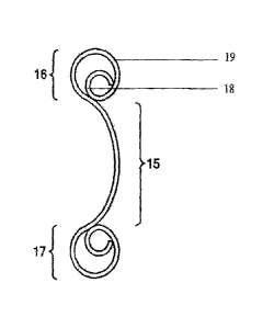
[0033] Reference numerals in Figures of embodiments of the present invention:
1- first guardrail plate subunit; 2- post; 3- clog-proof block;
4- reinforcing steel pipe; 5- assembly plate; 6- assembly bolt;
7- assembly nut; 8- connection bolt; 9- connection nut;
10- wire rope or steel strand; 11- second guardrail plate subunit;
12- first fixing bolt; 13- first fixing nut; 14- bolt hole;
15- guardrail plate body; 16- first energy-accumulating ring;
17- second energy-accumulating ring; 18- first steel pipe; 19- second steel
pipe.
7
CA 02747568 2011-06-17
DETAILED DESCRIPTION OF THE INVENTION
[0034] Hereinafter, the preferred embodiments of the present invention will be
described with
reference to drawings. It should be noted that the preferred embodiments
described herein are only
used for illustrating and explaining the present invention, but not intended
to limit the present
invention.
Embodiments of the Single-wave Beam Guardrail Plate
First Embodiment
[0035] According to one embodiment of the present invention, a single-wave
beam guardrail
plate is provided. As shown in Figs. 1 and 2, the embodiment includes a
guardrail plate body 15
integrally formed by rolling, and two energy-accumulating rings which have the
same structure
and are symmetrically disposed in the axial direction at the upper edge and
the lower edge of the
guardrail plate body 15. The cross section of the guardrail plate body 15 is
in the shape of arc. The
two energy-accumulating rings are formed by the upper edge and the lower edge
of the guardrail
plate body 15 being curled inwardly and helically toward a convex direction of
the guardrail plate
body 15, respectively.
[0036] Further, the cross section of each of the two energy-accumulating rings
described above is
of a pipe-in-pipe structure in which a first steel pipe 18 is inserted inside
a second steel pipe 19 and
connected with the inner wall of the second steel pipe 19. The walls of the
first steel pipe 18 and
the second steel pipe 19 have a common section near the convex portion of the
guardrail plate
body 15.
[0037] Further, for the two energy-accumulating rings described above, a
common tangent of an
outer circle of the first steel pipe 18 of the first energy-accumulating ring
16 and an outer circle of
the first steel pipe 18 of the second energy-accumulating ring 17 is
perpendicular to the radius of
the guardrail plate body 15. Similarly, a common tangent of an outer circle of
the second steel pipe
19 of the first energy-accumulating ring 16 and an outer circle of the second
steel pipe 19 of the
second energy-accumulating ring 17 is perpendicular to the radius of the
guardrail plate body 15.
[0038] Further, the middle point of the above common tangent of the outer
circle of the second
steel pipe 19 of the first energy-accumulating ring 16 and the outer circle of
the second steel pipe
19 of the second energy-accumulating ring 17 coincides with the middle point
of the arc of the
8
= CA 02747568 2014-03-10
guardrail plate body 15.
[0039] Further, a connection line between the center of the inner circle or
the outer circle of the
first steel pipe 18 of the first energy-accumulating ring 16 and the center of
the inner circle or the
outer circle of the first steel pipe 18 of the second energy-accumulating ring
17 is perpendicular
to the radius of the guardrail plate body 15. Similarly, a connection line
between the center of the
inner circle or the outer circle of the second steel pipe 19 of the first
energy-accumulating ring 16
and the center of the inner circle or the outer circle of the second steel
pipe 19 of the second
energy-accumulating ring 17 is perpendicular to the radius of the guardrail
plate body 15.
[0040] Further, the inner circle of the first steel pipe 18 is an inscribed
circle of the inner circle
of the second steel pipe 19 in the above first energy-accumulating ring 16 or
second
energy-accumulating ring 17.
[0041] Further, in the above pipe-in-pipe structure, the radius of the outer
circle of the first steel
pipe 18 is less than 60% of the radius of the outer circle of the second steel
pipe 19.
[0042] In addition, in this embodiment, circular or elliptical bolt holes 14
may be symmetrically
provided on the guardrail plate body 15.
Second Embodiment
[0043] The present embodiment is different from the above-described embodiment
in that the
radius of the outer circle of the first steel pipe is less than 55% of the
radius of the outer circle of
the second steel pipe in the above pipe-in-pipe structure.
Third Embodiment
[0044] The present embodiment is different from the above-described
embodiments in that the
radius of the outer circle of the first steel pipe is less than 50% of the
radius of the outer circle of
the second steel pipe in the above pipe-in-pipe structure.
Embodiments of the Single-wave Beam Steel Guardrail
First Embodiment
[0045] According to the embodiments of the present invention, based on the
above-described
single-wave beam guardrail plates, a single-wave beam steel guardrail is
provided. As shown in
Fig. 3, this embodiment includes a plurality of guardrail units sequentially
disposed in the
9
CA 02747568 2011-06-17
transverse direction. The plurality of guardrail units are connected by
assembling. A single-layer
guardrail plate subunit in each of the plurality of guardrail units is
connected with a corresponding
guardrail plate subunit in adjacent guardrail unit by assembling. In this
embodiment, the number
of the guardrail units may be determined according to the actual length of
roads or bridges. In
addition, the structure of the guardrail plate subunit is the same as that of
the single-wave beam
guardrail plate, referring to associated description of the embodiments of the
single-wave beam
guardrail plate, which will not described repeatedly.
[0046] Each of the plurality of guardrail units described above includes a
post disposed upright, a
single-layer guardrail plate subunit disposed transversely at the same side of
the post and being
perpendicular to the post, and an clog-proof block provided between the single-
layer guardrail
plate subunit and the post. The single-layer guardrail plate subunit and the
clog-proof block are
connected by assembling, and the clog-proof block and the post are connected
by assembling.
[0047] Further, an assembly plate for connecting adjacent guardrail plate
subunits is provided
near corresponding post at the connections between the single-layer guardrail
plate subunit of the
guardrail unit and corresponding guardrail plate subunit of the adjacent
guardrail unit. The
assembly plate and corresponding guardrail plate subunits are connected by
assembling, and the
assembly plate and corresponding clog-proof block are connected by assembling.
[0048] In the above embodiment, the above assembly plate may be a connection
steel plate, or
may be a guardrail plate without energy-accumulating rings. The plurality of
guardrail plate
subunits may be assembled by the connection steel plates or the guardrail
plates without
energy-accumulating rings. When assembled by the connection steel plates, two
single-wave beam
guardrail plates are connected and assembled by using a segment of steel plate
abut against the arc
guardrail plate body of the guardrail plate subunit. When assembled by the
guardrail plate without
energy-accumulating rings, the energy-accumulating rings (i.e. steel pipe) at
the upper side and the
lower side of both ends of one guardrail plate subunit are sawed, and the
remaining guardrail plate
body is disposed at the rear side of the guardrail plate bodies of adjacent
two guardrail plate
subunits and then the adjacent guardrail plate subunits are connected and
assembled by inserting
and tightening bolts through bolt holes preset on the adjacent two guardrail
plate subunits.
[0049] Further, a reinforcing steel pipe is provided in the axial direction in
the arc groove of the
single-layer guardrail plate subunit of each guardrail unit. The reinforcing
steel pipe is located
CA 02747568 2011-06-17
between corresponding assembly plate and clog-proof block. The guardrail plate
subunit and
corresponding assembly plate, the reinforcing steel pipe are connected by
assembling, and the
guardrail plate subunit and corresponding clog-proof block are connected by
assembling. In Fig. 3,
the post is indicated as 2, and the clog-proof block is indicated as 3, and
the reinforcing steel pipe
is indicated as 4, and the assembly plate is indicated as 5.
[0050] Specifically, in Fig. 3, the single-layer guardrail plate subunit, the
assembly plate, the
reinforcing steel pipe and the clog-proof block are sequentially assembled by
an assembly bolt 6
and an assembly nut 7, and the clog-proof block and the post are assembled by
a connection bolt 8
and a connection nut 9.
Second Embodiment
[0051] The present embodiment is different from the above-described first
embodiment in that,
wire ropes or steel strands respectively pass through two energy-accumulating
rings of the
single-layer guardrail plate subunit of each guardrail unit in the axial
direction to connect
corresponding guardrail plate subunits of the plurality of guardrail units,
such that a prestress is
generated in each guardrail plate subunit, which allows the single-wave beam
steel guardrail to
have a dual characteristics of semi-rigid guardrail and flexible guardrail. In
Fig. 3, the wire rope or
steel strand is indicated as 10.
[0052] In this embodiment, the wire ropes or steel strands pass through two
energy-accumulating
rings of the single-layer guardrail plate subunit. When a vehicle crashes with
the single-wave
beam steel guardrail, the single-layer guardrail plate subunits of the
guardrail units are assembled
together to withstand the force occurred as a whole; and when the single-layer
guardrail plate
subunit is in a critical situation, e.g., when the single-layer guardrail
plate subunit or the bolt is
about to be broken due to the tension, the wire ropes or steel strands will
play a role to combine the
guardrail plate subunits in the same layer of the guardrail units to withstand
the force together.
Third Embodiment
[0053] The present embodiment is different from the above-described first and
second
embodiments in that each layer of the above single-layer guardrail plate
subunit may be
single-side guardrail plate subunit, or may be double-side guardrail plate
subunit.
[0054] The structure of the single-side guardrail plate subunit is the same as
that of the
11
CA 02747568 2011-06-17
single-wave beam guardrail plate, and the double-side guardrail plate subunit
is formed by
assembling two single-wave beam guardrail plates together. As shown in Fig. 8,
in the double-side
guardrail plate subunit, the arc convex portions of the guardrail plate bodies
of the two
single-wave beam guardrail plates are disposed oppositely, and the guardrail
plate bodies are
connected by assembling.
[0055] In Fig. 8, the double-side guardrail plate subunit includes a first
guardrail plate subunit 1
and a second guardrail plate subunit 11. The guardrail plate body of the first
guardrail plate subunit
1 is connected with the guardrail plate body of the second guardrail plate
subunit 11 via a first
fixing bolt 12 and a first fixing nut 13.
Fourth Embodiment
[0056] According to the embodiments of the present invention, based on the
above-described
single-wave beam guardrail plates, a single-wave beam steel guardrail is
provided. As shown in
Figs. 4 and 5, this embodiment includes a plurality of guardrail units
sequentially disposed in the
transverse direction, and the plurality of guardrail units are connected by
assembling. Each
guardrail unit includes a plurality of posts disposed upright at intervals, a
plurality of layers of
guardrail plate subunits disposed transversely at the same side of the posts
and being perpendicular
to the posts, and a plurality of clog-proof blocks provided between the
plurality of layers of
guardrail plates and corresponding posts. The plurality of layers of guardrail
plate subunits and
corresponding clog-proof blocks are connected by assembling, and the clog-
proof blocks and
corresponding posts are connected by assembling. In this embodiment, the
structure of each
guardrail plate subunit is the same as that of the single-wave beam guardrail
plate, referring to
associated description of the embodiments of the single-wave beam guardrail
plate, which will not
described repeatedly. In Fig. 4, the post is indicated as 2.
[0057] The plurality of layers of guardrail plate subunits of each guardrail
unit and
corresponding guardrail plate subunits of adjacent guardrail unit are
connected by assembling.
[0058] In this embodiment, the number of the guardrail units may be determined
according to the
actual length of roads or bridges. Specifically, two posts and three layers of
guardrail plate
subunits may be provided in each guardrail unit. The two posts are disposed
upright, and the three
layers of guardrail plate subunits are disposed in the transverse direction.
[0059] Further, assembly plates for connecting adjacent guardrail plate
subunits are provided
12
CA 02747568 2011-06-17
near corresponding posts at the connections between three layers of guardrail
plate subunits of
each guardrail unit and corresponding guardrail plate subunits of the adjacent
guardrail unit. Each
assembly plate and corresponding guardrail plate subunit are connected by
assembling, and each
assembly plate and corresponding clog-proof block are connected by assembling.
In this
embodiment, the assembly plate may be a connection steel plate, or may be a
guardrail plate
without energy-accumulating rings. For details about the assembling by the
connection steel plate
and the guardrail plate without energy-accumulating rings, please refer to
associated description of
the above first embodiment, which will not described repeatedly.
[0060] Further, reinforcing steel pipes are provided in the axial direction in
the arc grooves of
three layers of guardrail plate subunits of each guardrail unit, respectively.
Each of the reinforcing
steel pipes is located between corresponding assembly plate and clog-proof
block. Each layer of
the guardrail plate subunits and corresponding assembly plates, the
reinforcing steel pipes are
connected by assembling, and each layer of the guardrail plate subunits and
corresponding
clog-proof blocks are connected by assembling.
[0061] Further, in each guardrail unit described above, the distances between
three layers of
guardrail plate subunits and corresponding posts are the same in the vertical
direction. The widths
and the thicknesses of three layers of guardrail plate subunits are the same
from the bottom to the
top, and the diameters of the energy-accumulating rings of three layers of
guardrail plate subunits
are the same from the bottom to the top.
[0062] Further, in each guardrail unit described above, the diameters of the
three reinforcing steel
pipes provided correspondingly to three layers of guardrail plate subunits are
the same from the
bottom to the top in the vertical direction.
Fifth Embodiment
[0063] The present embodiment is different from the fourth embodiment
described above in that,
wire ropes or steel strands respectively pass through two energy-accumulating
rings of each layer
of three layers of guardrail plate subunits of each guardrail unit in the
axial direction to connect
corresponding guardrail plate subunits of the plurality of guardrail units,
such that a prestress is
generated in each guardrail plate subunit, which allows the single-wave beam
steel guardrail to
have a dual characteristics of semi-rigid guardrail and flexible guardrail.
[0064] In this embodiment, the wire ropes or steel strands pass through two
energy-accumulating
13
CA 02747568 2011-06-17
rings of each layer of guardrail plate subunit. When a vehicle crashes with
the single-wave beam
steel guardrail, three layers of guardrail plate subunits of each guardrail
unit are connected
integrally by assembling to withstand the force as a whole; and when a certain
layer of guardrail
plate subunits is in a critical situation, e.g., when a certain layer of
guardrail plate subunits or bolt
is about to be broken due to the tension, the wire ropes or steel strands will
play a role to combine
the guardrail plate subunits in the same layer of the guardrail units to
withstand the force together.
In this embodiment, the wire ropes or steel strands are provided such that,
the single-wave beam
steel guardrail has not only the semi-rigid characteristics of the waveform
beam guardrail but also
the flexible characteristics of the flexible guardrail when being crashed by a
vehicle, which may
improve the protection ability and the cushioning ability of the single-wave
beam steel guardrail.
Sixth Embodiment
[0065] The present embodiment is different from the above fourth or fifth
embodiment in that,
each layer of the above three layers of guardrail plate subunits may be single-
side guardrail plate
subunit, or may be double-side guardrail plate subunit. For the structures of
the single-side
guardrail plate subunit and the double-side guardrail plate subunit, please
refer to associated
description of the third embodiment described above, which will not described
repeatedly.
Seventh Embodiment
[0066] The present embodiment is different from the above fourth to sixth
embodiments in that,
as shown in Fig. 6, in each guardrail unit, the diameters of the three
reinforcing steel pipes
provided correspondingly to three layers of guardrail plate subunits are
gradually reduced from the
bottom to the top in the vertical direction, and the wall thickness of them is
gradually increased
from the bottom to the top in the vertical direction.
[0067] For example, in this embodiment, the seamless steel pipe of 50mm outer
diameter may be
selected and used for the three reinforcing steel pipes provided
correspondingly to three layers of
guardrail plate subunits. From the bottom to the top, the wall thickness of
the bottom layer of the
reinforcing steel pipe is 3 mm, and the wall thickness of the middle layer of
the reinforcing steel
pipe is 4 mm, and the wall thickness of the top layer of the reinforcing steel
pipe is 5 mm.
Eighth Embodiment
[0068] The present embodiment is different from the above fourth to seventh
embodiments in
14
CA 02747568 2011-06-17
that, as shown in Fig. 7, in each guardrail unit described above, the
distances between three layers
of guardrail plate subunits and corresponding posts are gradually reduced from
the bottom to the
top in the vertical direction. For example, the perpendicular distance between
the bottom layer of
the guardrail plate subunit and corresponding post is approximately 30 mm
larger than the
perpendicular distance between the middle layer of the guardrail plate subunit
and corresponding
post, and the perpendicular distance between the middle layer of the guardrail
plate subunit and
corresponding post is approximately 30 mm larger than the perpendicular
distance between the top
layer of the guardrail plate subunit and corresponding post.
[0069] Further, in each guardrail unit described above, the widths and the
thicknesses of three
layers of guardrail plate subunits are gradually increased from the bottom to
the top in the vertical
direction. For example, from the bottom to the top, the thickness of the
bottom layer of the
guardrail plate subunit is 3 mm, and the thickness of the middle layer of the
guardrail plate subunit
is 4 mm, and the thickness of the top layer of the guardrail plate subunit is
4.5 mm.
[0070] Further, in each guardrail unit described above, the diameters of the
energy-accumulating
rings of three layers of guardrail plate subunits are gradually increased from
the bottom to the top
in the vertical direction.
[0071] In the first to eighth embodiments described above, in each guardrail
unit, three layers of
single-wave beam guardrail plates disposed horizontally and two posts disposed
upright may form
a frame of the guardrail unit having grading efficiency. When a vehicle
crashes with the
single-wave beam steel guardrail, the pipe-in-pipe structure of the guardrail
plate subunit is
deformed to be opened, curled and flattened, so as to absorb the vehicle
kinetic energy. Thus, by
grating cushion efficiency, the cushioning effect is significant, and the
collision time of the vehicle
with the single-wave beam steel guardrail is prolonged, and the collision
acceleration of the
vehicle with the single-wave beam steel guardrail is reduced, which may
prevent the vehicle from
going across or turning over laterally, and provide a good protection to
drivers and passengers. In
addition, the appearance of the present invention is ingenious and beautiful,
and the anti-collision
capability and cushioning capability are strong, which is applicable to roads,
urban roads and
bridges, especially applicable to speedways in cities in which small vehicles
are in a large
proportion, and may also be used as residential guardrails. The guardrail
according to the present
invention may be helpful to improve the overall safety protection ability and
the landscape design
CA 02747568 2011-06-17
level of roads and bridges.
[0072] In addition, according to the requirement of anti-collision grades
which are grade B,
grade A, grade SB, grade SA and grade SS respectively, in the guardrail units
according to the
above embodiments, the number of layers of the guardrail plate subunit, the
width of the guardrail
plate and the dimensions of the outer circle or the inner circle of the first
steel pipe and the second
steel pipe of each energy-accumulating ring may be set according to the
grades. For example,
when the anti-collision grade of the single-wave beam steel guardrail is grade
A, i.e. 160 kj, the
thickness of each layer of the guardrail plate subunits may be set to 3 mm.
[0073] Further, in the above embodiments of the single-wave beam guardrail
plate and the
single-wave beam steel guardrail, a post cap may be provided at the top of
each post.
[0074] To sum up, in the embodiments of the single-wave beam guardrail plate
and the
single-wave beam steel guardrail according to the present invention, the
single-wave beam
guardrail plate includes a guardrail plate body integrally formed by rolling,
and two
energy-accumulating rings which have the same structure and are symmetrically
disposed in the
axial direction at the upper edge and the lower edge of the guardrail plate
body. The cross section
of the guardrail plate body is in the shape of arc. The two energy-
accumulating rings are formed by
the upper edge and the lower edge of the guardrail plate body being curled
inwardly and helically
toward a convex direction of the guardrail plate body, respectively. Based on
the single-wave
beam guardrail plate, a single-wave beam steel guardrail is provided. When the
guardrail plate
subunit is being destroyed, corresponding energy-accumulating rings are
rapidly opened to absorb
the vehicle kinetic energy. When a big vehicle crashes with the single-wave
beam steel guardrail,
in the vertical direction, the guardrail plate subunit at the lower part of
the post having a relatively
low rigidity is firstly destroyed, and then above guardrail plate subunits
with a relatively high
rigidity are destroyed in turn. Thus, the vehicle kinetic energy may be
cushioned and steppedly
eliminated, and the collision time is prolonged to provide a good protection
for drivers and
passengers; so as to overcome the disadvantages of low anti-collision grade
and weak cushion
capacity and unsightly appearance in the prior art. Therefore, the advantages
of high anti-collision
grade, strong cushion capacity and beautiful appearance may be achieved.
[0075] It should be noted that the above description is only the preferred
embodiments of the
present invention, but not intended to limit the present invention. Though the
present invention is
16
CA 02747568 2013-05-27
described in detail with reference to the above embodiments, those skilled in
the art still
can make modifications to the technical solutions of the above embodiments, or
make
equivalent replacement for some technical features in these technical
solutions. The
scope of the claims should not be limited by the preferred embodiments set
forth in the
examples, but should be given the broadest interpretation consistent with the
description
as a whole.
17