Note: Descriptions are shown in the official language in which they were submitted.
CA 02747587 2013-04-16
WALL PANEL TRIM REVEAL SYSTEM AND METHOD
FIELD
[0001] The present disclosure relates to an improved wall panel trim reveal
system
and method, and more particularly to a trim reveal system and method for
cladding the
exterior of buildings with wall panels.
BACKGROUND
[0002] Wall panel trim systems and methods for installing wall panels are a
relatively economic way of cladding the surfaces of buildings. However, prior
wall panel
trim systems and methods often require significant time and skill to install,
as the trim
pieces may need to be cut to fine tolerances in order to avoid unsightly gaps
and to avoid
sharp edges.
[0003] In addition, prior wall panel trim systems and methods may not allow
for
proper moisture control, making wall panels vulnerable to premature wear and
moisture
damage when used for exterior applications.
[0004] What is needed is an improved wall panel trim reveal system and
method for
cladding the exterior of buildings with exterior wall panels which overcomes
at least some
of the drawbacks and limitations as described above.
SUMMARY
[0005] The present disclosure relates to an improved wall panel trim reveal
system
and method which utilizes a set of vertical, horizontal and corner trim pieces
designed to
be fitted together. In an embodiment, the horizontal pieces are sized and
configured to be
received within slots or tabs formed in the vertical trim pieces. As will be
explained in
1
CA 02747587 2011-07-29
more detail, this allows for a relaxation of tolerances in cutting the lengths
of the horizontal
pieces, as there is significant overlap of the tabs formed in the vertical
trim pieces over the
edge of the horizontal pieces.
[0006] In addition, the configuration of the installed horizontal, vertical
and corner
trim pieces forms a moisture drainage channel which directs moisture away from
the walls
of a building. Therefore, the present panel trim reveal system and method is
particularly
suitable for use with wall panels for exteriors, such as fiber cement panels
and the like, for
cladding the exterior of buildings in a fast, simple and inexpensive manner.
[0007] In the present disclosure, the term "reveal" or "reveals" refers to
portions of
the trim pieces that are visible after installation in order to provide a
visually appealing
architectural detail between the wall panels.
[0008] In an embodiment, the present wall panel trim reveal system includes
a
plurality of primary profiles and a plurality of alternate profiles for corner
trims, vertical trims
and horizontal trims, at least some of which are interchangeable, to ensure a
uniform
installation and trim reveal with many standard wall panels. The trim pieces
may be
provided in various standard lengths (e.g. ten foot lengths) that may be cut
down to size as
needed, or butted against one another in order to obtain longer trim lengths
as may be
needed. This standard length is illustrative, and it will be appreciated that
the trim pieces
may be cut to any other specified length as may be necessary.
[0009] In an embodiment, the trim pieces may be made from extruded metals,
such
as aluminum or aluminum alloys. The trim pieces may further include functional
and/or
visually appealing details, such as grooves cut into the profile, which may
remain in view
after installation. The trim pieces may also include other visually appealing
finishes, such
as various metallic colors achieved by utilizing an aluminum anodizing
process. Various
other means may be used to increase the visual appeal of the trim pieces
including the
use of paints and texturing, as may be desired.
[0010] In an embodiment, as an illustrative example, all trim pieces may
have half
inch tabs and/or half inch center reveals in order to provide a consistent
appearance for all
trim pieces within the system. It will be appreciated, however, that any other
measurement
may be used for the tabs and/or reveals to provide a visually attractive trim.
2
CA 02747587 2011-07-29
[0011] The
result is a fast and affordable wall panel trim reveal system and method
which improves upon certain limitations and drawbacks found in prior designs.
BRIEF DESCRIPTION OF THE DRAWINGS
[0012] FIGS.
1A ¨ 1D show cross-sectional views of various vertical corner and
edge trim pieces in accordance with various embodiments;
[0013] FIG. 1E
shows a cross-sectional detailed view of a vertical trim piece
interacting with a wall panel;
[0014] FIGS.
2A and 2B show perspective views of the trim pieces of FIGS. 1A and
1B with wall panels;
[0015] FIGS.
3A and 3B show perspective views of the trim pieces of FIGS. 1C and
1D with wall panels;
[0016] FIGS.
4A ¨ 4D show cross-sectional views of various horizontal trim pieces
in accordance with various embodiments;
[0017] FIG. 4E
shows a cross-sectional detailed view of the horizontal trim pieces of
FIGS. 4A ¨ 4C with a sloped ledge interacting with a wall panel;
[0018] FIGS.
5A ¨ 5C show perspective views of the horizontal trim pieces of FIGS.
4A ¨ 4C with wall panels;
100191 FIGS.
6A ¨ 6C show cross-sectional views of various vertical trim pieces with
interlocking protrusions;
[0020] FIGS.
7A and 7B shows the vertical trim pieces of FIGS. 6A ¨ 6C in an
interlocked position;
[0021] FIGS.
7C and 7D show the vertical trim pieces of FIGS. 6A and 6B being
interlocked with wall panels placed therebetween;
3
CA 02747587 2011-07-29
[0022] FIGS. 8A and 86 show perspective views of the interlocked vertical
trim
pieces of FIGS. 7A and 76 with wall panels;
[0023] FIGS. 9A and 96 show illustrative perspective views of an edge of a
horizontal trim piece being received within a groove or channel formed by a
tab of a
vertical trim piece;
[0024] FIGS. 9C and 9D show illustrative perspective views of an edge of
another
horizontal trim piece being received within a groove or channel formed by a
tab of another
vertical trim piece;
[0025] FIGS. 10A and 106 show cross-sectional views of vertical trim pieces
with
rotatable tabs in accordance with another embodiment;
[0026] FIGS. 11A and 116 show cross-sectional views of vertical corner trim
pieces
with the rotatable tabs of FIGS. 10A and 10B;
[0027] FIG. 11C shows a detailed cross-sectional view of a rotatable tab
with a
hinge having a non-circular shape;
[0028] FIG. 12A and 126 shows cross-sectional views of an alternative
vertical
corner trim piece with an interlocking tab; and
[0029] FIG. 13 shows a cross-sectional view of a vertical wall mount with
bumps.
DETAILED DESCRIPTION
[0030] As noted above, the present disclosure relates to an improved wall
panel trim
reveal system and method. More particularly the present disclosure relates to
a trim
reveal system including corner trims, vertical trims and horizontal trims for
cladding the
walls of buildings with wall panels. Various illustrative embodiments will now
be described
with reference to the drawings.
4
CA 02747587 2011-07-29
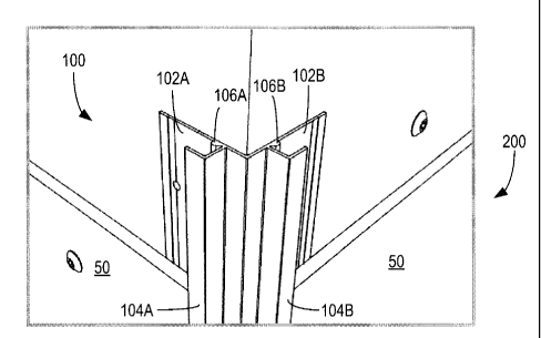
[00311 Now referring to FIGS. 1A ¨ 10, shown are cross-sectional views 100,
110,
120, 130 of various vertical corner and edge trim pieces in accordance with
various
embodiments.
[0032] As shown in FIG. 1A, a square outside corner trim piece 100 includes
mounting walls 102A, 102B substantially perpendicular to each other for
installation of the
trim piece at an outside corner of a building. Square outside corner trim
piece 100 further
includes tabs 104A, 104B attached on outer sides of mounting walls 102A, 102B
and
forming slots for receiving an edge of a horizontal trim piece. Square outside
corner trim
piece 100 further includes bumps 106A, 106B formed near the inside corners at
which
tabs 104A, 104B are attached to the outer sides of walls 102A, 102B. Portions
of square
outside corner trim piece 100 including tabs 104A, 104B are reveals which
remain visible
after installation.
[0033] VVith this configuration, horizontal trim pieces nest inside the
slots formed by
tabs 104A, 104B, and any wall panels (not shown) are kept close to tabs 104A,
104B by
bumps 106A, 106B. As will be explained in further detail below, this creates
an interior
moisture drainage channel down the entire length of one or more square outside
corner
trim pieces 100 installed at an outside corner of a building.
[0034] Now referring to FIG. 1B, an alternate round outside corner trim
piece 110 is
shown having mounting walls 112A, 112B substantially perpendicular to each
other and a
rounded corner piece attached at the corner of mounting walls 112A, 112B and
with tabs
114A, 114B forming slots for receiving edges of horizontal trim pieces
therein. Thus,
round outside corner trim piece 110 comprises two tabs formed from a double-
sided
rounded corner edge forming two slots, such that the two tabs and the rounded
corner
edge form the appearance of a continuous rounded corner.
[0035] Bumps 116A, 116B formed near the inside corners at which tabs 114A,
114B
are attached to mounting walls 112A, 112B serve the same functions as bumps
106A,
106B described for FIG. 1A above. In addition, round outside corner trim piece
110
includes stop flanges 118A, 118B to serve as a stop for edges of horizontal
trim pieces
received therein. The bumps 116A, 116B keep any wall panels (not shown) close
to tabs
114A, 114B and create an interior drainage channel within rounded outside
corner trim
CA 02747587 2011-07-29
piece 110. Portions of rounded corner trim piece 110 including a rounded
outside corner
and tabs 114A, 114B are reveals that remain visible after installation.
[0036] It will be appreciated that square outside corner trim piece 100 and
rounded
outside corner trim piece 110 may be interchangeable, depending on
architectural
preference. It will also be appreciated that various other corner profiles
incorporating tabs
and bumps may be designed in order to receive edges of horizontal trim pieces
and to
allow for visually attractive reveals which remain visible after installation.
[0037] Now referring to FIG. 1C, shown is an inside corner trim piece 120
for
installation at inside corners of buildings. Inside corner trim piece 120 has
mounting walls
122A, 122B that are substantially perpendicular to each other, and include
tabs 124A,
124B forming slots to receive edges of horizontal trim pieces. Bumps 126A,
126B formed
near the inside corner where tabs 124A, 124B are connected to mounting walls
122A,
122B keep any wall panels (not shown) close to tabs 124A, 124B in order to
form interior
drainage channels to control moisture. As shown in FIG. 1C, the two tabs 124A,
124B and
a corner formed by the mounting walls 122A, 122B therebetween together provide
the
appearance of a visually appealing triple corner at an outer corner of a
building.
[0038] Now referring to FIG. 10, shown is a vertical edge trim piece 130
that may
be used to terminate a vertical edge. As shown, vertical edge trim piece 130
includes
mounting wall 132, tab 134 forming a slot to receive an edge of a horizontal
trim piece, and
bump 136. Bump 136 serves to keep any wall panels (not shown) close to tab
134.
100391 FIG. 1E is a cross-sectional detailed view of a vertical trim piece
140. As
shown, vertical trim piece 140 includes mounting wall 142 and tab 144 forming
a slot for
receiving an edge of a horizontal trim piece 400. Bump 146 formed near an
inside corner
where tab 144 is connected to mounting wall 142 serves to keep wall panel 50
off of the
building wall and closer to tab 144. Bump 146 also forms a moisture drainage
channel
within vertical trim piece 140, allowing moisture 150 to drain down the length
of vertical
trim piece 140 and away from the building wall.
[0040] Now referring to FIGS. 2A and 2B, shown are perspective views 200,
210 of
the trim pieces of FIGS. 1A and 1B together with wall panels. As shown, FIG.
2A
illustrates square outside corner trim piece 100 with mounting walls 102A,
102B mounted
6
CA 02747587 2011-07-29
to a corner of a building. Tabs 104A, 104B form slots to receive edges of wall
panels 50,
and as earlier illustrated, bumps 106A, 106B keep wall panels 50 away from the
building
wall and close to tabs 104A, 1048. Similarly, FIG. 2B illustrates round
outside corner trim
piece 110 with mounting walls 112A, 11213 (hidden) mounted to a corner of a
building.
Tabs 114A, 114B form slots to receive wall panels 50 therein. Bumps 116A, 116B
(hidden) keep wall panels 50 away from the building wall and close to tabs
114A, 114B.
[0041] FIGS. 3A and 3B show perspective views 300, 310 of the trim pieces
of
FIGS. 1C and ID together with wall panels. As shown in FIG. 3A, inside corner
trim piece
120 is mounted to an inside corner of a building by mounting walls 122A, 122B
(hidden).
Tabs 124A, 124B form slots to receive edges of wall panels 50 and bumps 126A,
126B
(hidden) keep wall panels 50 away from the building wall and close to tabs
124A, 124B.
FIG. 38 shows vertical edge piece 130 mounted by mounting wall 132. Tab 134
forms a
slot to receive an edge of wall panel 50, and bump 136 keeps wall panel 50
away from the
building wall and close to tab 134.
[0042] FIGS. 4A ¨ 4D show cross-sectional views of various horizontal trim
pieces
in accordance with various embodiments. For example, FIG. 4A shows a single
slope
horizontal trim piece 400 having mounting wall 402, a slope 404, and a
horizontal reveal
406. Horizontal trim piece 400 may be used as a base horizontal trim, and also
be used
above frames for windows and doors. As noted earlier, single slope horizontal
trim piece
400 is sized and shaped to fit within a slot formed in any corner piece or
vertical edge
piece described above with reference to FIGS. 1A ¨ 3B.
[00431 All horizontal trim pieces 400, 410, 420, 430 described with respect
to FIGS.
4A ¨ 4D are sized and shaped to be received in slots formed in any corner trim
or vertical
edge trim pieces described above, and to butt up against bumps formed in the
corner trim
or vertical edge trim pieces. No cuts have to be exactly precise because the
reveals of the
vertical trims allow for some tolerance in the cut lengths of the horizontal
trim pieces to fit
into and be visually covered by the tabs in the vertical trim pieces. This fit
and finish aspect
of the tabs in the vertical trim pieces also removes any sharp cut edges to be
visible and
avoids safety hazards as the sharp cut edges slide into the vertical trim
profiles.
[0044] FIG. 4B shows a double slope horizontal trim piece 410 having a
mounting
wall 412, slopes 414A, 414B, and two horizontal reveals 416A, 416B. An outer
portion of
7
CA 02747587 2013-04-16
mounting wall 412 between reveals 416A, 416B is also visible after
installation. The two
horizontal reveals 416A, 416B and center reveal (i.e. the outer portion of
mounting wall
412 visible between the two horizontal reveals 414A, 414B match the visual
appearance of
vertical trim pieces to be described with respect to FIGS. 6A ¨ 6C below,
without trapping
any moisture between the two horizontal reveals 414A, 414B.
[0045] It is believed by the inventor that the profile shown in FIG. 4B
did not
previously exist in the exterior trim market. Commonly, installers will use a
Z trim profile in
combination with a vertical H trim. The overall design is not consistent, as
the horizontal
trim is a single tab with no center reveal and the vertical trim has two tabs
with a center
reveal. A J trim and a H trim cannot be used horizontally as they trap water,
snow, ice and
moisture and this compromises the performance of the set in panel and the
building
envelope.
[0046] FIG. 4C shows a modified horizontal trim piece 420 having a wall
422, slope
424, a horizontal reveal 426 and an underside reveal 428 which may be visible
from below
after installation. Thus, this trim piece is suitable for locations higher up
on the walls of
buildings which are visible to people from below.
[0047] Now referring to FIG. 4D, shown is a top horizontal trim piece 430
for use in
trimming the tops of wall panels. Top horizontal trim piece 430 includes
mounting wall
432, tab 434, and horizontal reveal 436. As will be appreciated, when wall
panels 50 are
installed vertically, Top horizontal trim piece 430 may abut one or more of
horizontal trim
pieces 400, 410 and 420.
[0048] Now referring to FIG. 4E, shown is a cross-sectional detailed view
440 of the
horizontal trim pieces of FIGS. 4A ¨ 4C with slopes 404, 414A, 414B, 424
interacting with
a wall panel 50. As shown, a slight gap is formed between wall panel 50 and
slopes 404,
414A, 414B, 424, whereby any moisture from behind wall panel 50 may escape and
drain
away from the building and the trim.
[0049] Currently, horizontal trims available on the market are designed
with a 90
degree angle. This does not drain water away from the building and may in fact
hold water
and contribute to snow and ice buildup. After experimentation, the inventor
has
determined that a downward slope of approximately 3 degrees to 10 degrees from
8
CA 02747587 2013-04-16
. .
,
horizontal is preferable, although even greater angles are possible. More
preferably, a
slope of between 5 degrees and 8 degrees may be used for the sloped portions
of the
horizontal trim pieces of FIGS. 4A ¨ 4C. In a preferred embodiment, a 6.6
degree slope
may be used for all slopes in the horizontal trim pieces.
[0050] Now referring to FIGS. 5A ¨ 5C, shown are perspective
views 500, 510, 520
of the horizontal trim pieces of FIGS. 4A ¨ 40 interacting with wall panels.
As shown in
FIG. 5A, single slope horizontal trim piece 400 may be mounted by mounting
wall 402, and
slope 404 may be near the bottom of wall panel 50. Horizontal reveal 406
remains visible
after installation of wall panel 50. As wall panel 50 is mounted to the wall
as well by
suitable fasteners, it is important to note that the horizontal trim pieces
need not be load
bearing. Therefore, as noted, slope 404 may be set at an angle greater than 10
degrees if
desired, as slope 404 does not need to bear the weight of wall panel 50.
[0051] Now referring to FIG. 5B, shown is a double slope
horizontal trim piece 410
mounted by mounting wall 412. Slope 414A is near the bottom of wall panel 50,
but as
noted, slope 414A does not bear the load of wall panel 50, which is mounted
independently to the building wall. As shown, horizontal reveals 416A, 416B,
slope 414B
and the outer side of mounting wall 412 between horizontal reveals 416A, 416B
are all
visible after installation of double slope horizontal trim piece 410.
[0052] Now referring to FIG. 5C, shown is an alternate single
slope horizontal trim
piece 420 mounted by mounting wall 422, where slope 424 is abutting the bottom
of wall
panel 50. Once again, slope 424 does not bear the load of wall panel 50, and
therefore
may be sloped beyond 10 degrees if desired. Horizontal reveal 426 and
underside reveal
428 may remain visible after installation.
[0053] As noted earlier, in the vertical trim pieces, the bumps
(e.g. bumps 106A,
106B of FIG. 1A) are positioned near the inside corners of where tabs (e.g.
tabs 104A,
104B of FIG. 1A) are connected to the mounting walls (e.g. mounting walls
102A, 102B of
FIG. 1A). As best shown in FIG. 1E, in one embodiment, theses bumps are shaped
as a
tear drop to act as a moisture barrier and create a moisture drainage path
within the trim
assembly. Water is commonly driven by wind and driving rain into the corners
of buildings,
and the bumps allow the water that is driven into these corners to be
contained in the
corner of the trims and run down the moisture drainage channel formed by these
bumps.
9
'
CA 02747587 2013-04-16
The bumps also space the wall panel off of the water drainage area so that the
panel edge
does not remain in direct contact with the moisture within the covered trim
tabs.
[0054] Prior reveal trim products available to the market do not have any
drainage
elements incorporated into their design because most extruded aluminum reveal
products
have been designed for interior use. Thus, wall panels sitting in these prior
are always in
contact with areas of water collection, possibly compromising the long term
performance of
the set in panels and paint finish.
[0055] In contrast, the horizontal and vertical trim pieces of the present
disclosure
are designed to drain water away from the building walls by incorporating
slopes in
horizontal trim pieces (e.g. FIGS. 4A ¨ 4C) and moisture drainage channels
created by
placement of bumps near inside corners of the vertical trim pieces. Together,
these
unique details allow water, snow, ice, and moisture to freely drain away from
the wall
panels and building envelope.
[0056] Now referring to FIGS. 6A ¨ 6C, shown are cross-sectional views of
various
vertical trim pieces with interlocking protrusions. As shown in FIG. 6A,
vertical back plate
610 includes a mounting wall 612 for mounting, and two side walls 614A, 614B
forming a
channel. On the inner side of side walls 614A, 614B are locking protrusions
616A, 616B
for locking engagement with corresponding locking protrusions 626A, 626B (FIG.
6B)
found on a matching vertical top cap trim piece 620. Vertical top cap trim
piece 620
includes vertical reveals 622A, 622B, a recessed vertical reveal 628 and
matching profile
side walls 624A, 624B to be received in the channel of vertical back plate
610.
[0057] While not shown, vertical back plate 610 may include bumps similar
to the
bumps found in the other trim pieces (e.g. bumps 106A, 106B of FIG. 1A),
although such
bumps may be made smaller to keep the wall panels at an appropriate position.
[0058] FIG. 6C shows an alternate vertical top cap trim piece 630 having a
recessed
vertical reveal 638 and offset vertical reveals 632A, 632B for accommodating
wall panels
with different thicknesses. In this case, vertical top cap trim piece 630 has
locking
protrusions 636A, 6368 located at the same positions, but the profile side
walls 634A,
634B are sized differently. This may be used when transitioning from one type
of wall
panel to another type of wall siding having a different thickness.
CA 02747587 2013-04-16
[0059]
FIGS. 7A and 7B show, in illustrations 700 and 710, the pieces of FIGS. 6A ¨
6C in interlocked positions to illustrate the differences between vertical top
cap trim pieces
620 and 630. FIGS. 7C and 7D show in illustrations 720 and 730 in more detail
the
vertical trim pieces of FIGS. 6A and 6B being interlocked together with wall
panels 50
received therebetween. In use, vertical top cap trim piece 620 may be pushed
into locking
position within vertical back plate 610 using a rubber mallet, or some similar
tool.
[0060] Now
referring to FIGS. 8A and 8B, shown are some perspective views 800,
810 of the interlocked vertical trim pieces of FIGS. 7A and 7B with wall
panels. FIG. 8A
shows vertical top cap trim piece 620 used to trim two wall panels 50
separated by vertical
back plate 610. Advantageously, as vertical top cap trim piece 620 may be
installed
simply by tapping into place using a rubber mallet or some similar tool,
installation is very
quick, without the need for fasteners.
Advantageously, this snap locking system
significantly increases the efficiency of installation of these vertical trim
pieces, and is a
significant improvement over one piece H trim pieces where installers often
have to fight to
set a panel under the trim reveal tabs when the area is too small to allow
wall panels to be
set in place comfortably.
[0061] In
an embodiment, the present snap locking system also acts as a moisture
management system when used with horizontal trim profiles described earlier.
The
vertical back plate 610 butts up to a nailing flange of a horizontal trim
piece, and then the
vertical top cap trim piece 620 is locked in place. The vertical top cap trim
piece 620 then
slides down over the nailing flange of a horizontal back plate located on the
bottom edge
of the siding panel creating a shingled wall assembly and positive lap for
water to shed
down and away from the building envelope. On the top edge of a wall panel, the
vertical
top cap trim piece 620 once locked in place fits under the bottom tab of
single or double
slope horizontal trim pieces 400, 410 again to create a shingled positive
lapped
installation.
[0062]
FIGS. 9A and 9B show illustrative perspective views 900 and 910 of an edge
of a double slope horizontal trim piece 410 being inserted into a slot formed
by a tab of a
vertical edge piece 130. Similarly, FIGS. 9C and 9D show illustrative
perspective views
920 and 930 of an edge of a single slope horizontal trim piece 400 being
received within a
slot of a vertical edge trim piece 130.
11
CA 02747587 2013-04-16
. ,
, .
[0063] Now referring to FIGS. 10A and 10B, shown are cross-
sectional views 1000
and 1020 of vertical trim pieces with rotatable tabs in accordance with
another
embodiment. As shown, vertical trim piece 1000 includes a mounting wall 1002
with hinge
1004 and bump 1006. Hinge 1004 is configured to rotatably receive tab 1008.
Tab 1008
includes a complementary lock 1010. As shown in FIG. 10B, when tab 1008 is
rotated into
position, lock 1010 rotates about hinge 1004 and snaps into position by using
locking
elements provided on hinge 1004 and lock 1010. .
[0064] Now referring to FIGS. 11A and 11B, shown are cross-
sectional views 1100
and 1120 of vertical corner trim pieces with the rotatable tabs of FIGS. 10A
and 10B. As
shown, vertical corner trim piece 1100 includes mounting walls 1102A, 1102B
with hinge
sockets 1104A, 1104B located on outer sides of the mounting walls 1102A,
11028.
[0065] Bumps 1106A, 1106B perform a function analogous to the
bumps described
earlier for other vertical trim pieces. However, bumps 1106A, 1106B may have a
modified
shape, wherein the slope to right side of the tear drop shaped bump of FIG. 1E
has been
carved out to form a slight hook or C-shape. The modified profile of bumps
1106A, 1106B
acts as a moisture barrier and the hook or C-shape forms a moisture drainage
channel
within the vertical corner trim piece 1100.
[0066] Rotatable tabs 1108A, 1108B are rotatably hinged to walls
1102A, 1102B at
hinge sockets 1104A, 1104B, and further include locks 1110A, 1110B for locking
tabs
1108A, 1108B into position, as shown in FIG. 11B. When tabs 1108A, 1108B are
locked
into position, the profile of vertical corner trim piece 1100 is similar to
the profile of square
outside corner trim piece 100 of FIG. 1A. However, it will be appreciated that
the rotating
tabs 1108A, 1108B provide additional flexibility during wall panel
installation.
[0067] Now referring to FIG. 11C, shown is a detailed cross-
sectional view of
rotatable tab 1108B. More particularly, rotatable tab 1108B includes a non-
circular hinge
ball 1112B that, when rotated within hinge socket 1104B progressively becomes
harder to
turn due to increasing mechanical friction, such that when lock 1110B is used
to lock tab
1108B into position, tab 1108B is not slideable along its length within the
hinge socket
1104B.
12
CA 02747587 2011-07-29
[0068] Now referring to FIGS. 12A and 12B, shown are cross-sectional views
1200
and 1220 of an alternative vertical corner trim piece with an interlocking
tab. As shown in
FIG. 12A, in this embodiment, the vertical corner trim piece includes mounting
walls
1202A, 1202B, tab receiving arms 1204A, 1204B, bumps 1206A, 1206B, tabs 128A,
1208B, and tab locking arms 1210A, 1210B. FIG. 12B shows another view in which
the
tabs 1208A, 1208B (shown in stippled outline for clarity) are interlocked in
position by the
cooperating tab receiving arms 1204A, 1204B and tab locking arms 1210A, 1210B.
This
alternative vertical corner trim piece allows additional flexibility in
mounting wall panels
together with the trims, particularly if the wall panel is the last one being
inserted, and
there is little room to insert the wall panel into the slot formed by the
tabs.
[0069] Now referring to FIG. 13, shown is a cross-sectional view 1300 of a
mounting
wall 1310 having a plurality of bumps 1306A ¨ 1306D for spacing a wall panel
away from
the building wall. Mounting wall 1310 may be used in conjunction with any of
the trim
pieces described above.
[0070] Thus, in an aspect, there is provided a wall panel trim reveal
system for
cladding a wall with wall panels, comprising: horizontal trim pieces having at
least one
slope; vertical trim pieces having at least one tab forming a slot for
receiving one or more
horizontal trim pieces therein; the horizontal and vertical trim pieces when
installed
together with wall panels forming a moisture drainage channel to direct
moisture away
from the walls.
[0071] In an embodiment, each vertical trim piece further comprises at
least one
mounting wall adapted for mounting the vertical trim piece to a wall, and at
least one bump
formed near an inside corner of the slot at which the at least one tab is
attached to the
mounting wall, the at least one bump forming a moisture drainage channel along
each
vertical trim piece.
[0072] In another embodiment, the at least one bump is adapted to abut an
edge of
the horizontal trim piece received within the slot, such that a moisture
channel running
along the length of each vertical trim piece is not obstructed by the
horizontal trim piece.
13
CA 02747587 2011-07-29
[0073] In another embodiment, the at least one bump is adapted to abut any
wall
panels received within each vertical trim piece to keep the wall panels off
the wall and
close to the at least one tab.
[0074] In another embodiment, the at least one bump has a modified tear
drop
shape with a carve out one side forming a hooked shape, such that the hooked
shape
forms a moisture channel running along the length of each vertical trim piece.
[00751 In another embodiment, each corner vertical trim piece comprises
perpendicular mounting walls and two tabs forming slots for receiving two
horizontal trim
pieces therein, each of the slots having at least one bump forming a moisture
drainage
channel within each tab running along each vertical trim piece.
[0076] In another embodiment, an outside corner vertical trim piece
comprises two
tabs and a corner edge therebetween, such that the two tabs and the corner
edge form the
appearance of a triple corner.
[0077] In another embodiment, an outside corner vertical trim piece
comprises two
tabs formed from a double-sided rounded corner edge forming two slots, such
that the two
tabs and the rounded corner edge form the appearance of a continuous rounded
corner.
[0078] In another embodiment, each horizontal trim piece has a bottom ledge
with a
downward slope of between 3 degrees to 10 degrees from horizontal.
[0079] In another embodiment, each horizontal trim piece has a bottom ledge
with a
downward slope of between 5 degrees to 8 degrees from horizontal.
[0080] In another embodiment, each horizontal trim piece has a bottom ledge
with a
downward slope of 6.6 degrees from horizontal.
[00811 In another embodiment, the vertical trim pieces have at least one
rotatable
tab forming a slot for receiving one or more horizontal trim pieces therein.
[0082] In another embodiment, the at least one rotatable tab is rotatably
hinged to
mounting walls at a hinge socket, and further include locks for locking the
tabs into
position.
14
CA 02747587 2011-07-29
[0083] In another embodiment, the at least one rotatable tab is rotatably
hinged to
mounting walls at hinge sockets by a non-circular hinge ball that, when
rotated within the
hinge socket progressively locks the tab into position by increasing
mechanical friction,
thereby preventing the tab from sliding along its length within the hinge
socket.
[0084] In another embodiment, wall panel trim reveal system further
comprises a
vertical top cap trim piece adapted to trim two wall panels separated by
vertical back plate,
the vertical top cap trim piece having locking protrusions adapted to
interlock with
corresponding locking protrusions in a channel formed in the vertical back
plate.
[0085] In another embodiment, the vertical back plate includes at least one
bump
formed near a side wall forming the channel, the at least one bump forming a
moisture
drainage channel along the vertical back plate.
[0086] In another embodiment, the vertical back plate and vertical top cap
trim piece
are adapted to be interlocked by their locking protrusions without fasteners.
100871 In another embodiment, the vertical top cap trim piece has offset
vertical
reveal tabs adapted to receive wall panels of different thicknesses.
100881 While the above description provides examples of one or more systems
and
methods, it will be appreciated that other systems and methods may be within
the scope of
the present description as interpreted by one of skill in the art.