Note: Descriptions are shown in the official language in which they were submitted.
CA 02747797 2011-07-29
APPARATUS FOR IMPLANTING A PRELOADED LOCALIZATION WIRE
Field of the Invention
In one aspect, the invention relates generally to an apparatus for implanting
a localization
wire and more particularly to an apparatus comprising a retractable cannula
for implanting a preloaded
localization wire. In another aspect, the invention relates generally to a
method for implanting a localization
wire and more particularly to a method for implanting a preloaded localization
wire by retracting a cannula
relative to the localization wire.
Description of the Related Art
Localization wires are common devices for making nonpalpable lesions in a
tissue mass,
usually breast tissue. When such a lesion is identified with a medical imaging
technique, such as radiography
and ultrasonography, it is often desirable to position a localization wire or
other type of marker near the
lesion to facilitate locating the lesion during later procedures, such as
biopsy. Alternatively, a localization
wire can be placed in the tissue mass after a biopsy has been taken. In this
case, the localization wire marks
the location of the biopsy cavity for future procedures, such as removal of
the surrounding tissue or
therapeutic treatment. It is critical that the localization wire is accurately
implanted in the correct location.
Localization wires, which typically comprise an anchor portion and a wire
portion that extends from the
anchor and through the skin surface, are especially effective for indentifying
lesions or biopsy sites because a
practitioner can use the wire as a physical guide to the lesion rather than
solely relying on imaging
techniques. For the surgical excision of the lesion, the localization wire is
the preferred way for the surgeon
to locate the lesion.
To implant a localization wire, a needle is inserted into the tissue mass and,
with guidance
from imaging systems, the needle is positioned with its tip near a
predetermined location. Once the needle is
in place, the localization wire is manually threaded through the needle and
inserted into the predetermined
location. Thereafter, the needle is removed from the tissue mass, and the
localization wire remains in place at
the predetermined location. Alternatively, the needle is positioned with its
tip at the predetermined location,
the localization wire is manually advanced to the end of the needle, and the
needle is manually withdrawn
from the tissue mass. During either process, the wire can be inadvertently
displaced from the predetermined
location as the needle is removed. As a result, the localization wire can be
positioned deeper or shallower
than intended and, therefore, can inaccurately mark the predetermined
location. Further, if ultrasonography is
utilized for imaging, the procedure requires three hands: one to position the
needle, a second to hold the
ultrasonography transducer, and a third to feed the localization wire into the
needle and tissue mass. If the
three hands are not properly coordinated, then it can be difficult for the
practitioner to accurately position the
localization wire.
Devices containing preloaded wires have been developed to eliminate the need
to thread the
needle with the wire when the needle is inserted into the tissue mass. The
localization wire of such devices
can be implanted into the predetermined location by manual distal displacement
of the localization wire. The
-1-
CA 02747797 2013-10-18
practitioner can grasp the wire portion that extends from the proximal end of
the needle and
push the localization wire distally to insert the anchor position into the
tissue mass; however,
this process still requires three hands. Alternatively, the device can
comprise a plunger in
operative communication with the localization wire. Displacement of the
plunger into the
needle forces the distal end of the localization wire past the tip of the
needle and into the
predetermined location. The force applied to the plunger can affect the final
location of the
localization wire. In order to correctly position the anchor, the practitioner
must accurately
place the tip of the needle a sufficient distance from the predetermined
location and apply a
suitable force to the plunger to displace the localization wire into the
predetermined location.
to There
remains a desire amongst medical practitioners for a device that can
accurately
implant a localization wire and requires only a single hand, thus freeing the
other hand to
hold the imaging device. Such a device would make it possible for a single
person to
accurately place the localization wire.
SUMMARY OF THE INVENTION
Various aspects of the present invention may provide for an apparatus for
percutaneously implanting a localization wire within a tissue mass,
comprising: a handle
defining a hollow interior and an end; a cannula defining a lumen and having a
distal end
forming an insertion tip, wherein the cannula is slidably mounted to the end
for movement
relative to the handle between an insertion position and a retracted position;
a collar mounted
to the cannula and configured to define a key; a localization wire positioned
to extend from
the handle and into the lumen of the cannula, the localization wire having a
distal end that is
positioned near the insertion tip and contained within the lumen when the
cannula is in the
insertion position, wherein the localization wire comprises at least one
anchor adapted to
hold the localization wire in the tissue mass, the cannula and the
localization wire being
configured such that each of the at least one anchor remains completely
contained in the
cannula when the cannula is in the insertion position prior to the cannula
being moved to the
retracted position; a keyway shaped for receiving the key; an actuator
comprising a biasing
element in operable communication with the cannula and configured such that
when the key
and the keyway are unaligned the biasing element is in a charged condition and
when the key
2
= CA 02747797 2013-10-18
and the keyway are aligned the biasing element is in a discharged condition;
and a trigger
rotatably mounted to the handle and operably connected to the key such that
rotation of the
trigger from a ready position to a release position aligns the key with the
keyway to release
the biasing element from the charged condition to the discharged condition to
move the
cannula from the insertion position to the retracted position; wherein the
biasing element is
located within the hollow interior extending between the end and the collar to
retract the
cannula from the insertion position to the retracted position to expose the
distal end of the
localization wire to the tissue mass and expose each of the at least one
anchor to the tissue
mass without inducing movement of the localization wire, and with the cannula
being
removable from the localization wire in its entirety.
Various aspects of the present invention may provide for an apparatus for
percutaneously implanting a localization wire within a tissue mass,
comprising: a handle with
a hollow interior and an end; a cannula defining a lumen and having a distal
end forming an
insertion tip, the cannula being movable relative to the handle between an
insertion position
and a retracted position; a collar that extends mounted to the cannula to
define a key; a
localization wire located within the lumen and having a distal end near the
insertion tip when
the cannula is in the insertion position, wherein the localization wire
comprises at least one
anchor adapted to hold the localization wire in the tissue mass, the cannula
and the
localization wire being configured such that each of the at least one anchor
remains
completely contained in the cannula when the cannula is in the insertion
position prior to the
cannula being moved to the retracted position; and an actuator comprising a
keyway and a
spring located within the hollow interior and extending between the end and
the collar, the
spring configured for operation between a charged condition where the key and
the keyway
are unaligned and a discharged condition when the key and the keyway are
aligned; wherein
the actuator further comprises a trigger for controlling the operation of the
spring, the trigger
being operable between a ready position and a release position such that a
rotation of the
trigger from the ready position to the release position aligns the key and the
keyway to
thereby release the spring from the charged condition to the discharged
condition and move
the cannula from the insertion position to the retracted position.
2a
= CA 02747797 2013-10-18
Various aspects of the present invention may provide for the use of an
apparatus for
percutaneous implantation of a localization wire into a tissue mass, the
apparatus comprising
a cannula defining a lumen and having a distal end forming an insertion tip, a
collar mounted
to the cannula and configured to form a key, a localization wire pre-loaded
within the lumen
and having a distal end near the insertion tip, and an actuator connected to
the cannula and
operable between a charged condition when the key and a keyway shaped for
receiving the
key are unaligned and a discharged condition when the key and the keyway are
aligned in
order to effect relative movement of the cannula and the localization wire to
expose the distal
end of the localizing wire; wherein the lumen of the cannula is adapted for
completely
to
containing at least one anchor when the actuator is in the charge position and
the cannula is
in an insertion position prior to movement of the cannula from a retracted
position by
discharge of the actuator; wherein the insertion tip of the cannula and the
localization wire
are adapted for insertion into the tissue mass when the actuator is in a
charged condition; and
wherein the actuator is operable for discharging and retracting the cannula in
order to expose
the distal end of the localization wire and expose each of the at least one
anchor without
inducing movement of the localization wire, and wherein the actuator is
operable for
retraction of the cannula by rotation of a trigger in order to align the key
with the keyway to
cause release of the actuator from the charged condition to the discharged
condition.
Various aspects of the present invention may provide for the use of the
apparatus as
defined herein for percutaneously implanting a localization wire within a
tissue mass.
Various aspects of the present invention may relate to an apparatus for
percutaneously
implanting a localization wire within a tissue mass, the apparatus comprising:
a retractable
cannula defining a lumen and having a distal end forming an insertion tip, the
cannula being
movable between an insertion position and an implant position; a localization
wire located
within the lumen and having a distal end near the insertion tip when the
cannula is in the
insertion position, wherein the localization wire comprises at least one
anchor adapted to
hold the localization wire in the tissue mass; and wherein the apparatus
further comprises an
actuator in operable communication with the cannula and operable between a
charged
condition and a discharged condition to effect the relative movement of the
cannula between
the insertion position and the implant position to expose the distal end of
the localization
2b
= CA 02747797 2013-10-18
wire to the tissue mass; and the actuator further comprises a biasing element
operably
coupled to the cannula and a trigger for maintaining the actuator in the
charged condition and
the discharged condition wherein the movement of the trigger from the ready
position to the
released position operates the biasing element resulting in the cannula moving
from the
insertion position to the implant position.
In accordance with a non-limiting embodiment, the present invention relates to
a
localization wire comprising a wire shaft defining a longitudinal axis and
first and second
anchors extending from the wire shaft in opposing relationship.
In accordance with another non-limiting embodiment, the present invention
relates to
a localization wire suitable for marking a tissue. The localization wire
comprises a wire shaft
defining a longitudinal axis having a first end and a second end; and first
and second anchors
extending from the wire shaft in opposing relationship, the first anchor
forming a first acute
interior angle relative to the wire shaft, the second anchor forming a second
acute interior
angle relative to the wire shaft; wherein the first acute interior angle faces
the first end of the
wire shaft and the second acute interior angle faces the second end of the
wire shaft; and
wherein the first and second interior angles face each other.
An apparatus according to the invention for percutaneously implanting a
localization
wire within a tissue mass comprises a cannula defining a lumen and having a
distal end
forming an insertion tip, the cannula being moveable between an insertion
position and an
implant position; a localization wire located within the lumen an having a
distal end near the
insertion tip when the cannula is in the insertion position; and an actuator
in operable
communication with the cannula and operable between a charged condition and a
discharged
condition to effect the movement of the cannula between the insertion and
implant positions
by retracting the cannula relative to the localization wire. To implant the
localization wire
into the tissue mass, the cannula is inserted into the tissue mass and the
actuator is placed in
the discharged condition to retract the cannula from the insertion position to
the implant
position and expose the distal end of the localization wire to the tissue
mass.
The insertion tip is sharpened to aid in the insertion of the cannula into the
tissue
mass.
2c
CA 02747797 2013-10-18
The cannula further comprises at least one imageable portion, and the at least
one
imageable portion can comprise multiple spaced imageable portions.
The localization wire comprises at least one anchor for holding the
localization wire
in the tissue mass. The at least one anchor can comprise opposing anchors. The
at least one
anchor can be a barb, and the barb can be integrally formed with the
localization wire. The
localization wire can also comprise an imageable portion, and the imageable
portion can
comprise a change in contour of the wire.
2d
CA 02747797 2011-07-29
The actuator comprises a biasing element coupled to the cannula to move the
cannula from the
insertion position to the implant position. The actuator further comprises a
trigger operable between a
ready position and a release position for controlling the operation of the
biasing element. The biasing
element is a spring in operable communication with the trigger such that
movement of the trigger from
the ready position to the release position releases the spring from a
compressed state to an expanded
state to move the cannula from the insertion position to the implant position.
The apparatus further comprises a handle defining a hollow interior and an
end, with the
cannula being slidably mounted to the end. The spring is located within the
hollow interior and
extends between the end and a collar extending from the cannula.
The trigger is pivotally mounted to the handle and includes a finger that
abuts the collar when
the trigger is in the ready position, and can be pivoted to the release
position to remove the finger from
abutting contact with the collar to release the spring.
The collar forms a key and the apparatus further comprises a keyway shaped for
receiving the
key, and wherein the key is unaligned from the keyway when the actuator is in
the charged condition
and is aligned with the keyway when the actuator is in the discharged
condition. The trigger can be
rotatably mounted to the handle and operably coupled to the key such that
rotation of the trigger aligns
the key with the keyway to thereby release the spring. The trigger can form
the keyway and
displacement of the trigger to the release position aligns the key with the
keyway to thereby release the
spring.
The localization wire is contained entirely within the cannula and the handle.
An apparatus according to the invention for percutaneously implanting a
localization wire
within a tissue mass, comprises a handle with a hollow interior and an end; a
cannula defining a lumen
and having a distal end forming an insertion tip, the cannula being slidably
mounted to the end of the
handle and moveable between an insertion position and an implant position; a
localization wire located
within the lumen and having a distal end near the insertion tip when the
cannula is in the insertion
position; and an actuator operable between a charged condition and a
discharged condition to effect the
movement of the cannula between the insertion and implant positions by
retracting the cannula relative
to the localization wire. The handle, the cannula, the localization wire, and
the actuator form a self-
contained implanting apparatus for implanting the localization wire into the
tissue mass, whereby the
cannula is inserted into the tissue mass and the actuator is placed in the
discharged condition to retract
the cannula from the insertion position to the implant position and expose the
distal end of the
localization wire to the tissue mass.
The actuator comprises a biasing element operably coupled to the cannula to
move the cannula
from the insertion position to the implant position. The actuator further
comprises a trigger operable
between a ready position and a release position for controlling the operation
of the biasing element.
The biasing element is a spring operably coupled to the trigger such that
movement of the trigger from
the ready position to the release position releases the spring from a
compressed state to an expanded
-3-
CA 02747797 2011-07-29
state to move the cannula from the insertion position to the implant position.
The spring is located
within the hollow interior and extends between the end and a collar extending
from the cannula.
The trigger can be pivotally mounted to the handle and includes a finger that
abuts the collar
when the trigger is in the ready position, and can be pivoted to the release
position to remove the finger
from abutting contact with the collar to release the spring.
The collar forms a key and the apparatus further comprises a keyway shaped for
receiving the
key, and wherein the key is unaligned from the keyway when the actuator is in
the charged condition
and is aligned with the keyway when the actuator is in the discharged
condition. The trigger can be
rotatably mounted to the handle and operably coupled to the key such that
rotation of the trigger aligns
the key with the keyway to thereby release the spring. The trigger can form
the keyway and
displacement of the trigger to the release position aligns the key with the
keyway to thereby release the
spring.
The localization wire is contained entirely within the cannula and the
housing. The
localization wire comprises at least one anchor for holding the localization
wire in the tissue mass. The
at least one anchor can comprise opposing anchors. The at least one anchor can
be a barb, and the barb
can be integrally formed with the localization wire. The localization wire
further comprises an
imageable portion.
The cannula further comprises at least one imageable portion. The at least one
imageable
portion can comprise multiple spaced imageable portions. The insertien tip is
sharpened to aid in the
insertion of the cannula into the tissue mass.
A method according to the invention for percutaneously implanting a
localization wire into a
tissue mass comprises the steps of inserting a cannula with a pre-loaded
localization wire into the tissue
mass; and refracting the cannula relative to the localization wire to expose a
portion of the localization
wire to the tissue mass.
The retracting step comprises automatically retracting the cannula relative to
the localization
wire. The retracting step further comprises activating an actuator to effect
the automatic retraction of
the cannula. The retracting step comprises removing the cannula from the
tissue mass.
The insertion step further comprises using an imaging system for locating one
of the cannula
and the localization wire. The insertion step comprises locating an insertion
tip of the cannula at a
predetermined location within the tissue mass. The insertion tip of the
cannula can be located at a
biopsy site. The insertion step comprises positioning an imageable portion on
the cannula at a
predetermined location within the tissue mass.
The method further comprises a step of locating an imageable portion of the
localization wire
at a predetermined location within the tissue mass. The imageable portion of
the localization wire can
be located at a biopsy site.
A method according to the invention for percutaneously implanting a
localization wire into a
tissue mass using an apparatus comprising a cannula defining a lumen and
having a distal end forming
an insertion tip; a localization wire pre-loaded within the lumen and having a
distal end near the
-4-
CA 02747797 2011-07-29
insertion tip; and an actuator connected to the cannula and operable between a
charged condition and a
discharged condition to retract the cannula relative to the localization wire,
wherein the method
comprises the steps of inserting the insertion tip of the cannula and the
localization wire into the tissue
mass; and retracting the cannula relative to the localization wire to expose a
portion of the distal end of
the localization wire to the tissue mass.
The retracting step comprises automatically retracting the cannula relative to
the localization
wire. The retracting step further comprises displacing a trigger on the
actuator to release a biasing
element operably coupled to the cannula and thereby automatically retract the
cannula. The retracting
step further comprises retracting the cannula into an end of a handle with a
hollow interior. The
retracting step comprises removing the cannula from the tissue mass.
The insertion step further comprises using an imaging system for locating one
of the cannula
and the localization wire in the tissue mass. The insertion step comprises
locating the insertion tip of
the cannula at a predetermined location within the tissue mass so that when
the cannula is retracted, the
localization wire is exposed to the predetermined location. The insertion step
comprises locating the
insertion tip of the cannula at a biopsy site such that upon retraction of the
cannula, the localization
wire is located at the biopsy site. The insertion step comprises positioning
an imageable portion on the
cannula at a predetermined location within the tissue mass.
The insertion step comprises positioning at least one anchor on the
localization wire at a
predetermined location within the tissue mass so that when the cannula is
retracted, the at least one
anchor is embedded into the tissue mass at the predetermined location. The
method further comprises a
step of locating an imageable portion of the localization wire at a
predetermined location within the
tissue mass. The imageable portion of the localization wire can be located at
a biopsy site.
BRIEF DESCRIPTION OF THE DRAWINGS
In the drawings:
FIG. 1 is a perspective view of an apparatus for implanting a preloaded
localization wire
according to the invention, wherein the apparatus is shown in an uncocked
condition.
FIG. 2 is a perspective view identical to FIG. 1, wherein a grip portion is
illustrated in
phantom to show a spring-loaded cannula disposed inside the grip portion;
FIG. 3 is a sectional view of the apparatus in FIG. 1.
FIG. 4 is an exploded view of the apparatus in FIG. 1.
FIG. 5 is an enlarged perspective view of a key and a keyway of the apparatus
in FIG. 1.
FIG. 6 is an enlarged sectional view of the cannula and the key of the
apparatus in FIG. 1 and
showing the preloaded localization wire disposed therein.
FIG. 7 is perspective view of the apparatus in FIG. 1 inserted into a
predetermined location in
a tissue mass, wherein the apparatus is in a cocked condition and the cannula
is in an insertion position.
FIG. 7A is a front plan view of the key and keyway of the apparatus in FIG. 7
, wherein the
key and keyway are unaligned.
-5-
CA 02747797 2011-07-29
FIG. 8 is a perspective view of the apparatus in FIG. 1, wherein the cannula
is in an implant
position to expose the localization wire to the predetermined location of the
tissue mass.
FIG. 8A is a front plan view of the key and keyway of the apparatus in FIG. 8,
wherein the
key and keyway are aligned.
FIG. 9 is a plan view of the localization wire in FIG. 8 implanted in the
tissue mass, wherein
the apparatus has been removed from the localization wire.
FIG. 10 is a perspective view of a second embodiment of an apparatus for
implanting a
preloaded localization wire according to the invention, with the apparatus
shown in a cocked condition.
FIG. 11 is an exploded view of the apparatus in FIG. 10.
FIG. 12 is a perspective view identical to FIG. 10, wherein a handle is
illustrated in phantom
to show a spring-loaded cannula disposed inside the handle and the cannula is
in an insertion position.
FIG. 12A is a front plan view of a key and a keyway of the apparatus in FIG.
9, wherein the
key and keyway are unaligned.
FIG. 13 is a perspective view of the apparatus in FIG. 10, wherein the cannula
is in an implant
position to expose the localization wire.
FIG. 13A is a front plan view of the key and the keyway of the apparatus in
FIG. 13, wherein
the key and keyway are aligned.
FIG. 14 is a perspective view of a third embodiment of an apparatus for
implanting a
preloaded localization wire according to the invention, with the apparatus
shown in a cocked condition.
FIG. 15 is an exploded view of the apparatus in FIG. 14.
FIG. 15A is a front plan view of a trigger with a keyway from the apparatus in
FIG. 15.
FIG. 16 is perspective view identical to FIG. 14, wherein a handle is
illustrated in phantom to
show a spring-loaded cannula disposed inside the handle and the cannula is in
an insertion position.
FIG. 16A is a front plan view of a key and the trigger of the apparatus in
FIG. 16, wherein the
key and keyway are unaligned.
FIG. 17 is a perspective view of the apparatus in FIG. 14, wherein the cannula
is in an implant
position to expose the localization wire.
FIG. 17A is a front plan view of the key and the nigger of the apparatus in
FIG. 17, wherein
the key and keyway are aligned.
FIG. 18 is a plan view of a fourth embodiment of an apparatus for implanting a
preloaded
localization wire according to the invention, with the apparatus shown in a
cocked condition.
FIG. 19 is a sectional view of the apparatus in FIG. 18, wherein the cannula
is in an insertion
position.
FIG. 20 is a sectional view of the apparatus in FIG. 18, wherein the cannula
is in an implant
position to expose the localization wire.
FIG. 21 is an enlarged view of the end of the localization wire of FIG. 20.
FIG. 22 is a side view of an alternative localization wire with radially
offset opposing barbs.
FIG. 23 is a front view of the alternative localization wire of FIG. 24.
-6-
CA 02747797 2011-07-29
FIG. 24 is a perspective view of a fifth embodiment of an apparatus for
implanting a
preloaded localization wire according to the invention, with the apparatus
shown in the cocked position
and a cannula in the insertion position.
FIG. 25 is a perspective view similar to FIG. 24 except that the apparatus is
shown in the
uncocked position and the cannula in the implant position.
FIG. 26 is a longitudinal sectional view of the apparatus of FIG. 25.
DESCRIPTION OF THE INVENTION
The invention provides an apparatus for accurately implanting a localization
wire within a
tissue mass. The apparatus comprises a preloaded localization wire and a
cannula that retracts
proximally to expose the localization wire. Implantation of a localization
wire with the apparatus
requires only one hand.
Referring now to the figures, FIGS. 1-9 illustrate a first embodiment of a
implanting apparatus
10 according to the invention, which is capable of the percutaneous placement
of a localization wire at
a predetermined location, such as a lesion or a biopsy site, within a tissue
mass 150. The implanting
apparatus 10 comprises a handle 20 for housing a cannula 60, a localization
wire 80 partially contained
within the cannula 60, and an actuator 90 for displacing the cannula 60
relative to the localization wire
80. It will become apparent in the following description that the handle 20,
the cammla 60, the
localization wire 80, and the actuator 90 form a self-contained implanting
apparatus 10.
The handle 20 includes a grip portion 22 slidably mounted to a base portion 24
with a hollow
interior 26, a closed proximal end 28, and an open distal end 30. The base
portion 24 further comprises
diametrically opposed L-shaped grooves 36 adjacent the hollow interior 26.
Each groove 36, best
viewed in FIG. 5, has a circumferential recess 34 that forms one leg of the L
at the distal end 30and a
longitudinal keyway 32 that extends from an end of the circumferential recess
34 towards the proximal
end 28 to form the other leg of the L. A pair of diametrically opposed
resilient tabs 38 is located on the
outside surface of the base portion 24 near the distal end 30.
The grip portion 22 defines a hollow interior 40 (FIG. 3) and comprises a
distal end 42 with a
wall 43 having an aperture 41 for slidably mounting the cannula 60 and an open
proximal end 44 that
receives the distal end 30 of the base portion 24. Further, the grip portion
22 includes first and second
pairs 46 and 48 of diametrically opposed openings sized to receive the tabs
38. The first pair 46 of
openings is located near the proximal end 44, and the second pair 48 are
spaced from the first pair 46 at
a distance less than the length of the base portion 24. A transverse slot 50
formed between first and
second trigger arm stops 52 and 54 extends through the grip portion 22 near
the distal end 48. The
transverse slot 50 has an arc length substantially equal to that of the
circumferential recess 34 of the
groove 36.
The handle 20 is slidable between an uncocked condition, as illustrated in
FIGS. 1 -3, and a
cocked condition, as shown in FIG. 7. In the uncocked condition, the first
pair 46 of openings receives
the tabs 38, and the proximal end 44 of the grip portion 22 is near the distal
end 30 of the base portion
-7-
CA 02747797 2011-07-29
24. In the cocked condition, the second pair 48 of openings receives the tabs
38, and the proximal end
44 of the grip portion 22 is near the proximal end 28 of the base portion 24.
The interaction of the tabs
38 with the first and second pairs 46 and 48 of openings secures the handle 20
in the uncocked and
cocked conditions, respectively. When the grip portion 22 slides from the
uncocked condition to the
cocked condition, distal displacement of the first pair 46 of openings
deflects the resilient tabs 38
towards the base portion 24 such that the grip portion 22 can slide over the
tabs 38 until the second pair
48 of openings aligns with and receives the tabs 38.
Referring now to FIGS. 4 and 6, the cannula 60 defines a lumen 62 and
comprises a proximal
end 64 mounted to a key 66 and a distal end 68 that forms an insertion tip 65.
The key 66 includes a
collar 67 with diametrically opposed key projections 70 and a sheath 72 that
extends distally from the
collar 67 to encase the proximal end 64 of the cannula 60. The distal end 68
of the cannula 60 can be
sharpened to facilitate insertion into the tissue mass 150 (FIG. 7). Further,
cannula 60 comprises an
imageable portion 74, preferably at least at the distal end 68, for enhanced
visibility using common
imaging techniques, such as radiography, ultrasonography, and magnetic
resonance imaging (MRI).
Multiple imageable portions 74 can be spaced along the cannula 60 at
predetermined intervals and
effectively utilized as a ruler when disposed within the tissue mass 150.
Suitable cannula tips are
disclosed in U.S. Patent No. 5,490,521, issued February 13, 1996 to R. E.
Davis and G. L. McLellan,
which is incorporated by reference. Ultrasound enhancement technology is also
disclosed in U.S.
Patent No. 4,401,124, issued August 30, 1983 to J. F. Guess et al.; and U.S.
Patent No. 4,582,061,
issued April 15, 1986 to F. J. Fry.
With particular reference to FIGS. 4, 6 and 9, the localization wire 80
comprises a distal end
82 near which is located at least one anchor 84 for securing the loco lintion
wire 80 in the tissue mass
150. The anchor 84 in this embodiment is an integrally formed, single barb;
however, the anchor 84
can be in the form of a hook, a loop, a coil, a pair of opposing barbs, or any
other suitable form.
Similar to the cannula 60, the localization wire 80 can comprise an imageable
portion 86, at the distal
end 82 or along the entire length of the wire 80, for enhanced visibility
using common imaging
techniques, such as radiography, ultrasonography, and magnetic resonance
imaging (MRI). For
example, the surface contour of the localization wire 80 can change at certain
locations or at periodic
intervals, such that those locations appear different from the rest of the
wire 80 when using an imaging
technique. The change in contour can be achieved by etching to remove material
from the surface.
Another example of an imageable portion 86 is incorporation of beads or loops
into the wire 80 at the
distal end 82 or along the entire length of the wire 80 to provide a palpable
reference.
The cannula 60 is movable between an insertion position, as illustrated in
FIG. 1-3 and 7, and
an implant position, as depicted in FIG. 8. In the insertion position, the
cannula 60 extends distally
from the handle 20 to facilitate insertion into the tissue mass 150, and the
anchor 84 is preferably
completely contained within the cannula 60. In this embodiment, the key 66
abuts the distal end 30 of
the handle base portion 24, and the key projections 70 are seated in the
circumferential recesses 34 of
the grooves 36 but are spaced from the respective longitudinal keyways 32. The
configuration of the
-8-
CA 02747797 2011-07-29
key 66 relative to the grooves 36 when the cannula 60 is in the insertion
position is best viewed in FIG.
7A. In the implant position, the minute is proximally retracted into the
hollow interior 26 of the
handle 20, and the anchor 84 is located exteriorly of the cannula 60 and
exposed to the tissue mass 150.
In this embodiment, the key projections 70 are rotated relative to the
insertion position such that they
are aligned with the respective longitudinal keyways 32 to enable displacement
of the key 66 and,
therefore, the cannula 60 into the handle grip portion 24. The position of the
key projections 70
relative to the grooves 36 when the cannula 60 is in the implant position is
best seen in FIG. 8A.
The localization wire 80 and the cannula 60 are sized such that they are
independently
moveable. In other words, movement of the cannula 60 does not induce movement
of the localization
wire 80, and the localization wire 80 is free to move within and relative to
the cannula 60. As a result,
the localization wire 80 is stationary during retraction of the cannula 60,
and inadvertent displacement
of the localization wire 80 is avoided.
To ensure that the localization wire 80 does not move in response to the
movement of the
cannula 60, the localization wire 80 can have a portion that is fixed relative
to the handle or some other
structure that does not move with the cannula 60.
When the cannula 60 is in the insertion position, the localization wire 80 is
preloaded within
= the lumen 62 and extends into the hollow interior 26 of the handle base
portion 24, as seen in FIG. 3.
In particular, the distal end 82 of the localization wire 80 is positioned
near the insertion tip 65 such
that the cannula 60 sheaths the anchor 84, as shown in FIG. 6. If necessary,
the anchor 84.can be
compressed to fit within the lumen 62. When the cannula 60 retracts to the
implant position, the
localization wire 80 is stationary; therefore, the distal end 82 and anchor 84
of the localization wire 80
become exposed to their surroundings, as illustrated in FIG. 8. Because the
anchor 84 of the
localiznrion wire 80 is disposed near the cannula insertion tip 65 and is not
displaced during retraction
of the cannula 60, the practitioner only has to position the insertion tip 65
when the cannula 60 is
inserted into tissue mass 150.
The actuator 90 for automatically moving the cannula 60 from the insertion
position to the
implant position comprises a biasing element, which is shown as a spring 94
with a proximal end 93
and distal end 95, and a trigger 92 in operable communication with the key 66.
The trigger 92 includes
a hollow finger 96, which has open proximal and distal ends 98 and 100,
rotatably disposed in the grip
portion 22. Diametrically opposed longitudinal grooves 104 sized to receive
the diametrically opposed
key projections 70 extend from the proximal end 98 of the finger 96. The
spring 94 extends through
the hollow finger 96, with the proximal and distal ends 93 and 95 of the
spring 94 abutting the key
collar 67 and the wall 43 of the grip portion 22, respectively.
The trigger 92 further comprises a trigger arm 106 that extends radially from
the finger 96 and
through the transverse slot 50 in the grip portion 22. Movement of the trigger
arm 106 within the
transverse slot 50 rotates the trigger 92 between a ready position and a
release position. When the
trigger ann 106 is adjacent the first trigger arm stop 52 (FIG. 7), the
trigger 92 is in the ready position.
-9-
CA 02747797 2011-07-29
Movement of the trigger arm 106 to the second trigger arm stop 54 (FIG. 8)
places the trigger 92 in the
release position.
The actuator 90 is operable between a charged condition and a discharged
condition. When
the actuator 90 is in the charged condition, as in FIG. 7, the trigger 92 is
in the ready position, and the
spring 94 is in a compressed state. Additionally, the finger grooves 104
engage the key projections 70,
which are unaligned with the respective longitudinal keyways 32. "When the
actuator 90 is in the
discharged condition, as in FIG. 8, the trigger 92 is in the release position,
and the spring 94 is in an
expanded state. To move the actuator 90 from the charged condition to the
discharged condition, the
trigger arm 106 is circumferentially displaced along the transverse slot 50 to
effect rotation of the
finger 96 and to move the trigger 92 to the release position. Because the
finger grooves 104 are
engaged with the key projections 70, the key 66 rotates with the finger 96
until the key projections 70
align with the longitudinal keyways 32. Once the key projections 70 and the
longitudinal keyways 32
are aligned, the spring 94 expands from the compressed state and pushes the
cannula 60 to the implant
position. In FIG. 8, the spring 94 is not shown in order to provide a clear
illustration of the interior of
the implanting apparatus 10.
Referring again to FIG. 2, in operation, the apparatus 10 begins with the
handle 20 in the
uncocked condition and the cannula 60 in the insertion position. In this
position, the cannula 60 and
localization wire 80 are protected by the handle 20 from being bent or damaged
during handling prior
to implanting the localization wire 80. Even though the trigger 92 is in the
ready position, the spring
94 in the expanded state, and the finger grooves 104 are not engaged with the
key projections 70;
therefore, the actuator 90 is not yet in the charged condition. Consequently,
accidental discharge of the
actuator 90 when the apparatus 10 is in the =cocked condition is not possible.
To move the handle 20 to the cocked condition in FIG. 7, a practitioner
situates the proximal
end 28 of the body portion 24 against a surface and applies a proximal force
to the grip portion to slide
the grip portion 22 over the body portion 24. Alternatively, the body portion
24 can be pushed distally
into the grip portion 22. Movement of the handle 20 from the uncocked
condition to the cocked
condition exposes the cannula 60 and sets the actuator 90 in the charged
condition. In particular,
movement of the grip portion 22 displaces the actuator finger 96 towards the
body portion 24 and
transforms the spring 94 from the expanded state to the compressed state. As
the finger 96 approaches
the key 66, the finger grooves 104 engage the key projections 70. The cannula
60 with the localization
wire 80 therein remains in the insertion position.
With the apparatus 10 in the condition shown in FIG. 7, the cannula 60 is
inserted into the
tissue mass 150 so that its insertion tip 65 is at the predetermined location,
which is illustrated as a
lesion 160 in FIGS. 7 and 8. Preferably, the cannula 60 with the localization
wire 80 contained therein
is positioned within the tissue mass 150 by using the imageable portions 74 in
conjunction with a
suitable imaging system. As stated above, only the cannula insertion tip 65
requires positioning when
the cannula 60 is inserted into the tissue mass 150. The design of the
apparatus 10 enables the
practitioner to use one hand to move the handle 20 to the cocked condition and
insert the cannula 60
-10-
CA 02747797 2011-07-29
into the tissue mass 150; the other hand can hold an ultrasonic transducer to
aid in positioning the
cannula 60 and the localization wire 80.
Retelling now to FIG. 8, to implant the localization wire 80, the
practitioner, preferably using
the same hand as above for cocking and inserting the apparatus 10, moves the
actuator 90 to the
discharged condition by rotating the trigger arm 106 from the first trigger
arm stop 52 to the second
trigger arm stop 54 to move the trigger 92 from the ready position to the
release position. As discussed
earlier, rotation of the trigger arm 106 induces rotation of the finger 96 and
the key 66. Upon sufficient
rotation of the key 66, the key projections 70 align with the longitudinal
keyways 32, thereby enabling
proximal displacement of the cannula 60. Once alignment is achieved, the
spring 94 simultaneously
expands from the compressed state and forces the cannula 60 to the implant
position. The cannula 60
retracts relative to the stationary localization wire 80 and into the handle
20. Preferably, the retracted
cannula 60, including the insertion tip 65, is contained entirely within the
handle 20 for safety
purposes. Retraction of the cannula 60 exposes the distal end 82 of the
localization wire 8010 the
tissue mass 150, and the anchor 84 deploys at the predetermined location to
embed the localization
wire 80 in the tissue mass 150. Advantageously, the localization wire 80 does
not move during the
implant process, and, consequently, the anchor 84 is embedded where the
practitioner positions it
during insertion, which greatly improves the placement accuracy over the prior
art. After the anchor 84
is implanted at the predetermined location, the apparatus 10 is removed from
the localization wire 80,
which remains in the tissue mass 150, as depicted in FIG. 9.
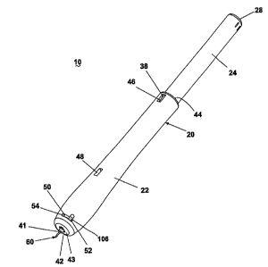
A second embodiment of an implanting apparatus 10' according to the invention
is illustrated
in FIGS. 10-13A where similar components are identified with the same
reference numeral bearing a
prime (') symbol. The second embodiment is very similar to the first
embodiment; the primary
difference is the handle 20' of the second embodiment. The first embodiment
handle 20 comprises the
grip portion 22 and the body portion 24, which are initially in an uncocked
condition. Conversely, the
second embodiment handle 20' is a single element having a cap 200 at its
proximal end 28' and a distal
wall 43' with an aperture 41' for slidably receiving the cannula 60'. The
handle 20' does not have a
similar uncocked condition; rather, the second embodiment is assembled and
shipped in the cocked
condition, with the cannula being exposed to the surrounding environment.
Referring to FIGS. 11-13A, instead of grooves 36 on the inside surface of the
handle 20, the
second embodiment handle 20' comprises a keyway disk 202 disposed adjacent to
the proximal end 98'
of the trigger finger 96'. The keyway disk 202 includes a keyway 32' having a
shape corresponding to
that of the key collar 67' and the key projections 70'. In the illustrated
embodiment, the keyway 32'
comprises a circular portion 206 and diametrically opposed rectangular
portions 208. When the
cannula 60' is in the insertion position in FIG. 12, the anchor 84' of the
localization wire 80' is retained
within the cannula 60', and the key 66' abuts the distal side of the keyway
disk 202 and is oriented such
that the key projections 70' are not aligned with the rectangular portions
208. This configuration, best
viewed in FIG. 12A, prevents movement of the cannula 60' through the keyway
32'. When the cannula
60' is in the implant position shown in FIG. 13, the key projections 70' are
rotated relative to the
-11-
CA 02747797 2011-07-29
insertion position such that they are aligned with rectangular portions 208 of
the keyway 32' to enable
displacement of the key 66' and, therefore, the cannula 60' into the hollow
interior 26' of the handle 20',
and the anchor 84' of the localization wire 80' is exterior of the cannula 60'
and exposed to the
surrounding tissue. In FIG. 13, the spring 94' is not shown in order to
provide a clear illustration the
interior of the apparatus 10'. The position of the key projections 70'
relative to the keyway 32' when
the cannula 60' is in the implant position is best seen in FIG. 13A.
The operation of the second embodiment is substantially the same as, if not
identical to, the
operation of the first embodiment, excluding the cocking step. Because the
second embodiment
apparatus 10' is initially in a cocked condition, the operation begins with
the step of inserting the
cannula 60' into the tissue mass 150'. Once the cannula 60' and the
localization wire 80' are at the
predetermined location, the practitioner rotates the trigger arm 106' within
the transverse slot 50' to
move the trigger 92' from the ready position to the release position and
thereby align the key
projections 70' with the longitudinal keyways 32'. Upon alignment, the spring
94' expands and forces
the cannula 60' to the implant position to expose the distal end 82' of the
localization wire 80' to the
tissue mass 150'. After the anchor 84' is secured in the tissue mass 150', the
apparatus 10' is removed
from the localization wire 80'.
. A third embodiment of an implanting apparatus 10" according to the
invention is illustrated in
PIGS, 14-17A where similar components are identified with the same reference
numeral bearing a
double prime (") symbol. The primary difference between the second and third
embodiments is the
actuator trigger 92". The third embodiment trigger 92", which is best seen in
FIG, 15A, comprises a
keyway 32" corresponding to the shape of the key 66", a recess 34" offset from
the keyway 32", and a
surface 302 designed to support a finger of the practitioner. The trigger 92"
is mounted to a transverse
slot 304 in the handle 20" and is slidably movable between the ready and
release positions. The nigger
92" of the third embodiment effectively replaces the keyway disk 202 of the
second embodiment.
When the cannula 60" is in the insertion position shown in FIG. 16, the key
collar 67" abuts
the distal side of the trigger 92" and resides in the recess 34" such that the
collar 67" is unaligned with
the keyway 32". This configuration, best viewed in FIG. 16A, corresponds to
the ready position of the
trigger 92". In the ready position, the trigger 92" prevents retraction of the
cannula 60" relative to the
localization wire 80". To move the cannula 60" to the implant position shown
in FIG. 17, the trigger
92" slides to the release position, wherein the keyway 32" aligns with the key
collar 67" to enable
displacement of the key 66" and, therefore, the cannula 60" into the hollow
interior 26" of the handle
20". In FIG. 17, the spring 94" is not shown in order to provide a clear
illustration the interior of the
apparatus 10". The position of the key projections 70" relative to the keyway
32" when the trigger 92"
is in the release position is best seen in FIG. 17A.
The operation of the third embodiment is substantially the same as the
operation of the second
embodiment; the primary difference is the operation of the actuator 90",
particularly the trigger 92".
Rather than rotating the trigger arm 106' through the transverse slot 50', the
trigger 92" is actuated by
-12-
CA 02747797 2011-07-29
pishing on the surface 302 to slide the trigger 92" through the transverse
slot 304 from the ready
position to the release position.
A fourth embodiment of a implanting apparatus 10'" according to the invention
is illustrated in
FIGS. 18-20, where similar components are identified with the same reference
numeral bearing a triple
prime ("') symbol. The fourth embodiment is substantially the same as the
second and third
embodiments, with the fourth embodiment illustrating an alternative actuator
trigger 92".. The trigger
92" includes a surface 400 designed to support a finger of the practitioner
and comprises a pivot arm
402 that terminates in a finger 404. The trigger 92" is mounted to the handle
20" at a pivot pin 406
and is pivotable between ready and release positions.
When the trigger 92" is in the ready position shown in FIG. 19, the finger 404
abuts the
proximal side of the collar 67" to support the cannula 60" against the bias of
the spring 94" and retain
the cannula 60"' in the insertion position. To move the trigger 92"' to the
release position, downward
force applied to the surface 400 pivots the trigger 92'" about the pivot pin
406 to remove the finger 404
from abutting contact with the collar 67". As a result, the biasing force of
the spring 94" moves the
cannula 60" to the implant position.
The operation of the fourth embodiment is substantially the same as the
operation of the
second and third embodiments; the primary difference is the operation of the
actuator 90", particularly
the actuation trigger 921". To discharge the actuator 90", the practitioner
simply applies a downward
force to the surface 400 of the trigger 92".
In the descriptions of various embodiments of the implanting apparatus 10, the
localization
wire 80 has been shown as being completely disposed within the cannula 60 and
the handle 20.
However, it is within the scope of the invention for the localization wire 80
to extend through and
beyond the proximal end 28 of the handle base portion 24. Such a configuration
would facilitate
implantation of a longer localization wire 80 with the same size apparatus 10.
To avoid accidental injury prior to insertion of the cannula 60 into the
tissue mass 150, the
apparatus 10 can optionally include a removable sheath or removable safety cap
that encases the
exposed portion of the cannula 60 or at least the insertion tip 65 of the
cannula 60.
Referring to FIGS. 20 and 21, the localization wire 80" has some unique
features compared to
a traditional localization wire. The localization wire 80" comprises opposing
anchors formed by
opposing sets of barbs 84" that extend from the shaft of the localization
wire. The opposing sets of
barbs 84" resist the movement of the localization wire in either direction
along the longitudinal axis of
the shaft.
Preferably, and as illustrated, the opposing barbs are angled in opposite
directions relative to
the shaft. That is, each barb forms an acute interior angle relative to the
shaft, but the acute interior
angle faces towards an opposite end of the shaft. The opposing barb structure
is ideal for use in less
dense or structurally strong tissue, such as fatty tissue.
-13-
CA 02747797 2011-07-29
FIGS. 22 and 23 illustrates another localization wire 80" incorporating the
opposing barbs
84", which in this case are radially offset to each other and are not arranged
in sets as in the
localization wire 80".
The opposing barbs can be arranged in a variety of different ways. They can be
arranged in
cooperative sets, individual barbs or a combination of both. There can be an
equal or unequal number
. of opposing barbs. The barbs can be radially aligned or unaligned.
The barbs can also be formed in a variety of ways. For example, the barbs can
be integrally
formed with the shaft of the localization wire, such as in bending a portion
of the shaft. Alternatively,
the barbs can be separate pieces affixed to the shaft, such as by laser
welding separate wire elements to
the shaft.
FIGS. 24-26 illustrate a fifth embodiment apparatus 510 for implanting a
localization wire.
The fifth embodiment 510 comprises a handle 520, with a hollow interior 526. A
passageway 527
extends from the hollow interior 526 to the nose or distal end of the handle
520. A longitudinal slot
529 is formed in the upper surface of the ha dle 520 and extends to the hollow
interior 526.
A cannula 560 is slidably received within the passageway 527 and can
reciprocate relative to
the handle. A trigger 592 in the form of a slide is received within the slot
529 and is slidably moveable
between the opposing ends of the slot. A proximal end of the cannula 560 is
mounted to the trigger,
such that the sliding movement of the trigger in the slot 529 effects the
sliding movement of the
cannula 560 relative to the handle 520.
A localization wire 580 is preloaded into the cannula. The sliding of the
cantata into the
handle results in the exposing of the localization wire to the environment
previously surrounding the
cannula.
In operation, the apparatus 510 is grasped by the user in the condition as
illustrated in FIG. 24.
In this condition, the apparatus is cocked and the cannula is in the insertion
position. The user then
inserts the cannula into the tissue mass, directly or through a positioning
cannula, and locates the
cannula as desired. The user then slides the trigger 592 to the release
position as illustrated in FIG. 25,
which causes the cammla to retract relative to the localization wire and
expose the localization wire to
the surrounding tissue. The user can then pull on the handle to withdraw the
cannula from the tissue,
leaving the localization wire.
The main difference between the fifth embodiment and the prior embodiments is
that the
cannula is manually moved from the insert position to the implant position.
The prior embodiments
automatically, not manually, moved the cannula. While the manual movement of
the fifth embodiment
is a more simple implementation, it is not preferred over the automatic
implanting. It is believed that
the automatic implanting is more accurate in that the user will be less like
to move the apparatus
relative to the tissue mass, thereby increasing the accuracy of the placement
of the localization wire.
The inventive apparatus for percutaneously implanting a localization wire
offers several
advantages. Because the process of implanting the localization wire involves
retracting the cannula
without axial displacement of the localization wire, the practitioner can
position the localization wire,
-14-
CA 02747797 2011-07-29
which only requires positioning the insertion tip of the cannula, at the
desired implantation location
during insertion of the apparatus into the tissue mass. This feature
facilitates accurate placement of the
localization wire within the tissue mass, which is critical to pinpointing the
predetermined location
during future procedures. Retraction of the entire cannula, including the
insertion tip, into to the handle
prevents accidental injury during removal of the device. Additionally, the
actuator of the inventive
apparatus retracts the cannula automatically, thereby ensuring that a suitable
force is applied to the
cannula and reducing the possibility of human error. Because the inventive
apparatus has a preloaded
= localization wire and can be operated with a single hand, the
practitioner can utilize the other hand to
control an imaging system and does not require the assistance of a third hand.
Furthermore, the first
embodiment of the apparatus is provided in an uncooked condition wherein the
spring is in an
expanded state, which not only prevents accidental discharge but also
increases the shelf life of the
spring and, therefore, the apparatus.
While the invention has been specifically described in connection with certain
specific
embodiments thereof, it is to be understood that this is by way of
illustration and not of limitation, and
the scope of the appended claims should be construed as broadly as the prior
art will permit.
-15-