Note: Descriptions are shown in the official language in which they were submitted.
CA 2747884 2017-02-23
- 1 -
,
LIGHT BARRIER
The invention relates to a light barrier having a
transmitter for a light beam and at least one associated
receiver, and having a light path that runs between a first
side and a second side of a region to be monitored.
Such light barriers are known in numerous embodiments. In
these, they can be designed in very different sizes and
meet very different aims. Thus, for example, the contour of
a motor vehicle is scanned inside a car wash system with
the aid of appropriately movably arranged light barriers,
in order to ensure the vehicle dries as effectively as
possible with the least possible outlay on air and energy.
It is also known to design very small light barriers in the
form of so-called fork light barriers, in the case of which
the light path extends between two limbs of a housing.
Such light barriers are used, for example, as edge
detectors in production machines in which webbed materials
are transported in an accurately positioned fashion. If a
relatively large limb separation is required for such a
fork light barrier, the fork light barrier is replaced by
another fork light barrier whose housing has the required
limb spacing and in which the supply line to the
transmitter in the one limb and to the receiver in the
other limb is laid in a suitable way. The use of light
barriers of different size at a point of use therefore
proves to be troublesome and complicated with reference to
handling and stock keeping.
It is the object of the invention to design a light barrier
of the type mentioned at the beginning so that it can be
flexibly constructed and used for different purposes.
CA27478M2017-3
- 2 -
,
Certain exemplary embodiments can provide a light barrier
having at least one transmitter and at least one receiver
for a light beam, and having a light path that runs between
a first side and a second side of a region to be monitored,
wherein the transmitter and receiver are situated on the
first side, and an optical system that picks up a primary
light beam emitted by the transmitter is arranged on the
second side, which deflects the primary light beam and
returns it to the receiver via the light path to the first
side as a secondary light beam, which is separate from the
primary light beam, at a distance from the primary light
beam, and wherein the distance between the two sides of the
light path is variable and the two sides of the light path
are implemented on limbs of a common housing whose distance
from one another is variable.
Other embodiments provide a light barrier where the
transmitter and the at least one receiver are situated on
the first side, and in that an optical system that picks up
the primary light beam emitted by the transmitter is
arranged on the second side, which deflects the primary
light beam and returns it to the receiver via the light
path to the first side as a secondary light beam, which is
separate from the primary light beam, at a distance from
the primary light beam.
CA 02747884 2016-08-11
- 2a -
The inventive light barrier therefore has a design by
means of which the light beam emitted by the transmitter
reaches via the light path an optical system on the other
side of the region to be monitored and is deflected there
such that there is returned from the second side to the
first side a secondary beam that runs at a distance from
the primary light beam. It is possible in this case to
utilize only the secondary light beam for the light
barrier function. In this case, the primary light beam at
one point can run via the light path that is insensitive
to interference to the light beam. For example, the
primary light beam can also run inside a hose-like or
tubular protective arrangement.
As an alternative hereto, it is also possible to utilize
the primary light beam for the light barrier function by
having the receiver detect an interruption of the primary
light beam or of the secondary light beam.
In a preferred embodiment of the invention, the optical
system arranged on the second side has a focusing device
for the secondary light beam. A high signal intensity is
provided in this way for the receiver, and
CA 02747884 2011-06-21
WO 2010/072200 - 3 -
PCT/DE2009/001774
so a high signal-to-noise ratio is attained for the
light barrier function.
In one variant of the invention, the optical system on
the second side can include an expanding device for
forming an expanded secondary light beam. Light barrier
monitoring can thereby be performed for a monitoring
region of two-dimensional cross section, the receiver
on the first side preferably having a converging lens
arrangement. An interruption of only a part of the
surface of the light beam then leads in the receiver to
a reduction in amplitude that can be evaluated as
measurement signal in the receiver.
Furthermore, the receiver in such an arrangement can be
designed as a receiver sensitive in two dimensions, so
that the position of the partial interruption of the
widened light beam can be established in the receiver.
In this case, the receiver can have a phototransistor
array, for example.
The inventive arrangement generally has the advantage
that the electronic components which need a power
supply and, possibly, a signal line are located on the
same side of the region to be monitored. In the case of
a fork light barrier, these components are located in
the same limb of the housing. Consequently, it is
possible to avoid troublesome cable laying,
particularly in the case of relatively long light
paths. A particular advantage occurs owing to the fact
that the arrangement of transmitter and receiver on the
same side of the region to be monitored enables a
compact control of the intensity of the light beam
emitted by the transmitter as a function of the
intensity of the light beam received by the receiver.
Consequently, according to the invention this control
does not require a control signal to be transmitted
from the receiver to the transmitter via the light
path. According to the invention, therefore, in a
CA 02747884 2011-06-21
WO 2010/072200 - 4 -
PCT/DE2009/001774
preferred embodiment There is arranged on the first
side a control stage with the aid of which the
intensity of the primary beam emitted by the
transmitter can be controlled as a function of the
intensity of the secondary beam received by the
receiver.
The inventive light barrier further permits the optical
system receiving the primary light beam, on the second
side to use beam splitter arrangements to generate a
plurality of secondary light beams that are preferably
fed back to the first side in a fashion parallel to one
another. Here, for each secondary light beam it is
possible to provide a dedicated receiver on the first
side. However, it is also possible to guide the
different secondary light beams generated on the second
side to a common receiver which either has a
sufficiently large sensitive surface, or is essentially
designed as a point receiver for which the secondary
light beams traverse the light path obliquely relative
to one another so that all secondary light beams strike
the same receiver and add together optically. However,
in this case information relating to the secondary
light beam interrupted by an object is lost, and so the
parallel arrangement of the secondary light beams and a
receiver arrangement, which can detect each secondary
light beam differentially, is generally preferred. The
receiver therefore preferably has a plurality of
receiver elements for in each case one secondary light
beam.
Conversely, the present invention also enables a design
having a plurality of primary light beams which are
condensed on the second side to form a common secondary
light beam.
The invention enables the simple design of a fork light
barrier whose limb spacing is variable. Since cabling
need be done only in one limb, there is no problem in
CA 02747884 2011-06-21
WO 2010/072200 - 5 -
PCT/DE2009/001774
adjusting the distance of the other limb
telescopically, because no cables or lines need also be
guided. Such a fork light barrier can be used with a
plurality of secondary light barriers for
differentiated monitoring, for example of the
instantaneous position of the edge of a material web,
and is therefore suitable, for example, for edge
monitoring even of material webs of different width. It
is also conceivable to indicate that a position of the
edge of the material web has been reached and, for
example, to trigger an alarm when another position
within the light barrier is reached by the edge of the
material web.
The customary expressions "light barrier" and "light
beam" are being used to explain the invention without
hereby intending a restriction to the visible light. Of
course, the "light beam" in the meaning of the
invention can also have a wavelength outside visible
light, that is to say be an infrared beam or
ultraviolet beam, for example. The suitability of
appropriate transmitters and receivers for the
formation of a "light barrier" depends on the
respective intended use and is known without more ado
to the person skilled in the art.
The invention is to be explained in more detail below
with the aid of exemplary embodiments illustrated in
the drawing, in which:
figure 1 is a schematic of an inventive light barrier;
figure 2 is a schematic of possible arrangements on
the first side and on the second side;
figure 3 is a schematic of a first embodiment of a
fork light barrier;
CA 02747884 2011-06-21
WO 2010/072200 - 6 -
PCT/DE2009/001774
figure 4 is a schematic of a fork light barrier having
one primary light beam and a plurality of
secondary light beams, or a plurality of
primary light beams and one secondary light
beam;
figure 5 is a schematic of a fork light barrier in
accordance with figure 3 for the purpose of
emitting an expanded primary light beam;
figure 6 shows an exemplary embodiment of a light
barrier in a housing, in use with expanded
light beams;
figure 7 shows another exemplary embodiment of a light
barrier having an expanded light beam;
figure 8 is a schematic of the design of a car wash
system having numerous light barriers;
figure 9 is a schematic of the design of a light
barrier for the purpose of scanning the
contour of a motor vehicle in a car wash
system; and
figure 10 is a schematic of the design of a light
barrier arrangement for the purpose of
detecting a vehicle position in a wash
system.
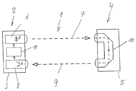
Figure 1 is a schematic of a light path 1 that runs
through a region to be monitored and is limited on a
first side 2 by a first part 3, and on a second side 4
by a second part 5 of a light barrier.
The first part 3 of the light barrier includes a
transmitter 6 for emitting a primary light beam 7 and a
receiver 8, arranged offset from the transmitter 6, for
receiving a secondary light beam 9.
CA 02747884 2011-06-21
WO 2010/072200 - 7 -
PCT/DE2009/001774
The second part 5 of the light barrier does not include
any electronic components, but merely an optical system
that serves to deflect the primary beam 7 and
5 returns the light beam to the first part 3 of the light
barrier as secondary light beam 9 at a distance from
the first light beam 7. In the exemplary embodiment
illustrated, the primary light beam 7 and secondary
light beam 9 run parallel to one another.
Located in the first part 3 of the light barrier
between the transmitter 6 and the receiver 8 is an
evaluation and control stage 11 that can be used to
execute the actual light barrier function by having the
evaluation and control stage 11 establish whether Lhe
secondary light beam 9 has been interrupted by an
object. Moreover, the evaluation and control stage 11
can further establish the intensity of the secondary
light beam 9 received by the receiver 8, and set the
intensity of the primary light beam 7 emitted by the
transmitter 6 as a function of the established
intensity of the secondary light beam 9. This prevents
the evaluation of the light barrier function by the
evaluation and control stage 11 from being impaired by
an excessively strong or excessively weak primary light
beam 7. The evaluation and control stage 11 is
therefore capable of controlling the transmitter 6 so
that an effectively evaluable signal of an intensity
within a prescribed intensity interval arrives at the
receiver 8. Furthermore, it is possible to provide on
the first side 2 a switching stage (not illustrated)
with the aid of which the light beam 7 from the
transmitter 6 can be emitted in sections or in pulsed
form. In this case, the receiver 8 or the evaluation
and control stage 11 can be driven by the switching
stage with the aid of appropriate switching signals, in
order to receive or evaluate secondary light beams 9
only during the emitted light beams 7.
CA 02747884 2011-06-21
WO 2010/072200 - 8 -
PCT/DE2009/001774
Figure 2 shows a plurality of possible designs of the
inventive light barrier. On the second side 3, the
primary light beam 7 emitted by the transmitter 6 on
the first side 2 of the light path 1 reaches a
converging lens 12 with the aid of which the light is
coupled into a light guide 13. The deflection of the
primary light beam 7 on the second side 3 is undertaken
with the aid of the light guide. Located at the output
of the light guide 13 is a concave lens 14 with the aid
of which the secondary light beam 9 is formed by
expansion. The secondary light beam 9 strikes a
converging lens 15 on the first side 2 and can, in
turn, be coupled into a light guide 16 for guiding the
secondary light beam 9 to the receiver 8 on the first
side 2. As has already been described with the aid of
figure 1, the evaluation and control stage 11 is
arranged between the receiver 8 and the transmitter 6.
The design explained is illustrated in figure 2 with
unbroken lines, while a conceivable alternative
embodiment is depicted with stages drawn with dashes.
Accordingly, the primary light beam 7 reaches a
deflecting mirror 17 via the converging lens 12 on the
second side 3, and can then be coupled into a light
guide 13'. This light guide 13' can, if appropriate,
also be omitted. Via a further deflecting mirror 18,
the light beam is deflected anew by 90 and strikes the
concave lens 14. In a corresponding way, after
traversing the converging lens 15 the secondary light
beam 9 can be guided on the first side 2 onto a
deflecting mirror 19, in order to be directed onto the
receiver 8. If appropriate, the light beam can be
guided to the receiver 8 via a light guide 16'.
In the case of the exemplary embodiment illustrated in
figure 3, a light barrier is formed by a housing 19
that is of L-shaped design with two limbs 20, 21.
CA 02747884 2011-06-21
WO 2010/072200 - 9 -
PCT/DE2009/001774
The first limb 20 includes the electronic components,
while the second limb 21 carries in a displaceable
fashion a housing part 22 in which the optical system
(not illustrated here) for deflecting the light beam
5 is located.
It is indicated schematically in figure 3 that the
transmitter 6 and receiver 8 are arranged in the first
limb 20 so that the limb 20 forms the first side 2 of
10 the light path 1 located between the first limb 20 and
the housing part 22. The transmitter 6 emits the
primary light beam 7 that is deflected in the housing
part 22 and guided back to the receiver 8 as secondary
light beam 9. For reasons of clarity, the evaluation
and control stage 11 also present here is not depicted.
Figure 3 indicates by elements, depicted with dashes,
for the transmitter 6 and receiver 8, and for an
appropriately inverted beam path with the primary light
beam 7 and the secondary light beam 9 that the
locations for the transmitter 6 and the receiver 8 can
also be interchanged inside the first limb 20.
Provided in the first limb 20 in the case of the
exemplary embodiment illustrated in figure 4, whose
mechanical design corresponds to that of the exemplary
embodiment from figure 3, are three transmitters 6
which therefore emit three primary light beams 7. The
three light beams are combined in the optical system in
the housing part 22 and guided back to the receiver 8
as a secondary light beam 9, as is illustrated in
figure 4 by continuous boxes.
The light barrier function can be carried out over a
specific region with the aid of the three primary light
beams, the illustrated design of a fork type light
barrier having a housing part 22 whose distance from
the first limb 20 is variable being advantageous. The
evaluation of the secondary light beam 9 received by
CA 02747884 2011-06-21
WO 2010/072200 - 10 -
PCT/DE2009/001774
the receiver 8 can be performed by detecting the
received intensity, indicating whether only one of the
primary light beams 7, two of the primary light beams
7, or all three of the primary light beams 7 have been
interrupted by an object within the fork light barrier.
If it is also the aim in this case further to detect
which of the three primary light beams has, as the case
may be, been interrupted, it is possible to emit the
three primary light beams 7 in multiplex form with the
aid of the transmitters 6, the evaluation and control
stage 11 (not illustrated) included in the first limb
having information available as to which of the
three primary light beams 7 has been emitted within a
specific time window. The alternating frequency between
15 the emitted primary light beam sections can in this
case be so high that continuous primary light beams 7
are emitted in practice for the light barrier function,
although the evaluation and control stage 11 can
distinguish the three primary light beams 7 on the
20 basis of the respective time window even when only one
secondary light beam 9 is generated.
Figure 4 shows with dashed boxes that here, as well,
the reverse beam path is possible by having the
transmitter 6 emit a primary light beam 7 that is split
into three secondary and mutually parallel running
light beams 9 in the optical system 10 (not
illustrated) in the housing part 22. In this case, it
is possible to provide in the first limb 20 of the
housing 19 three receivers 8 that are respectively
assigned one of the secondary light beams 9. It is
primarily the secondary light beams 9 that serve here
as measuring beams. However, the utilization of the
primary light beam 7 as measuring light beam is also
not excluded.
Figure 5 shows an exemplary embodiment that corresponds
to the exemplary embodiment illustrated with the aid of
figure 3, the only point being that the primary light
CA 02747884 2011-06-21
WO 2010/072200 - 11 -
PCT/DE2009/001774
beam 7 emitted by the transmitter 6 is shaped into an
expanded parallel light beam by a diverging optical
system (not illustrated). In the housing part 22 on the
second side 4, the expanded light beam 7 is recondensed
by a focusing optical system into a narrow light beam
and deflected in the housing part 22, in order to be
guided back again to the receiver 8 on the first side 2
as a narrow secondary light beam 9. On being expanded,
the primary light beam 7 covers a larger cross section
of the light path 1. Through the use of an analog
evaluation of the amplitude of the secondary light beam
9 received via the transmitter 8, it is possible in
this case to establish the extent to which the expanded
light beam 7 has, if appropriate, been interrupted by
an object. It is possible hereby to reach conclusions
on the size of the object interrupting the light beam
7, and on the position of the object between the limb
and the housing part 22, as can follow from the
respective application.
Figure 6 illustrates an arrangement of a housing 19'
that is provided with a further second limb 21' so that
the housing part 22 is guided at both its ends into the
second limbs 21, 21', while the electronic system of
the light barrier is arranged in the first limb 20.
Provided in figure 6 are two transmitters 6, whose
emitted light beam has been widened in two dimensions
by a lens arrangement (not illustrated) so as to
produce a two-dimensional light beam which extends in
the plane of the drawing in figure 5. The deflecting
optical system 10 that is present in the housing part
22 and illustrated separately in a schematic fashion in
figure 6 is arranged so that in the illustration of
figure 6 the incident primary light beam 7 is deflected
downward, that is to say below the plane of the
drawing, and is guided back as a secondary two-
dimensional light beam 9 to the first limb 20, where
the two secondary light beams 9 respectively strike a
CA 02747884 2011-06-21
WO 2010/072200 - 12 -
PCT/DE2009/001774
receiver 8, it being possible to cancel the expansion
of the light beam 7, 9 by an appropriate focusing
optical system.
The arrangement of figure 6 permits objects passing
through the rectangular inner surface of the housing
19' to be detected, for example for counting purposes.
A similar arrangement results for an annular detector
such as is illustrated in figure 7. The primary light
beam 7 of a transmitter 6 is also expanded in two
dimensions here, it being possible to detect in
figure 7 only the portion of the primary light beam 7
that fills up the inner free space of an annular
diaphragm 23. Provided at the end, opposite the
transmitter 6, of the annular diaphragm 23 is the
deflecting optical system 10 (illustrated separately in
figure 7) which deflects the incident primary light
beam 7 downward with the aid of a total reflection
prism so that a corresponding two-dimensional secondary
light beam 9 below the plane of the drawing in figure V
is guided back onto the receiver 8 arranged under the
transmitter 6. This light barrier also serves for
counting all the objects that fall through the interior
of the perforated diaphragm 23. It is clear that what
matters here is not the material of the objects, and so
- as opposed to conventional ring sensors - all the
objects can be detected irrespective of their material.
Figure 8 is a schematic of a car wash system 24 with a
car 25 located therein. In order for the car 35 to be
driven into the car wash system 24, a roller door 26
located at the entrance to the car wash system 24 is
opened, specifically by means of a light barrier 27
with the aid of which the presence of a car 25 in front
of the car wash system 24 is detected. The car 25 is
positioned in the car wash system 24 with the aid of
light barrier detectors 28, 29 that are located on a
support frame 30 which can be moved on rails in the
CA 02747884 2011-06-21
WO 2010/072200 - 13 -
PCT/DE2009/001774
longitudinal direction of the car wash system 24, as
indicated by a double arrow A. The support frame
comprises two movable side pillars 31 planted on either
side of the car 25 on rails, rollers or the like. At
their lower end, the pillars 31 have a light barrier
detector 32 for detecting the position of wheels 33 of
the car 25.
The upper ends of the pillars 31 are interconnected by
a cross beam (not illustrated) so that the support
frame has the form of an inverted U. The cross beam is
fitted so high that the support frame 30 can be moved
alongside and over the top of cars 25 of a maximum
permissible total height.
Whereas for the wash operation, for example with the
aid of rotating brushes, the contour of the car 25 is
scanned by measuring the pressure at the brush holders,
contact with the car 25 is not desired for the
subsequent drying. Consequently, the contour of the car
is scanned with the aid of light barrier detectors
34 or 35. The two light barrier detectors are arranged
on the support frame 30 such that the height can be
moved, so that they can, in particular, determine the
25 upper contour of the car 25 when the support frame 30
is moved axially at the car 25 along the upper contour
of the car 25 required for drying. This makes it plain
that there is no need for the light barrier detectors
34 and 35 to be present at the same time in a car wash
system 24, since one of the two light barrier detectors
34, 35 regularly suffices.
According to the invention, an advantageous utilization
of the present invention is provided for the various
light barrier detectors that are illustrated in
figure 8.
In the view of figure 8, the first side may be located
downstream of the car 25. Located on this side are the
CA 02747884 2011-06-21
WO 2010/072200 - 14 -
PCT/DE2009/001774
transmitter 6, receiver 8 and evaluation and control
stage 11, which are indicated here schematically in a
circle. A primary light beam is transmitted by means of
the transmitter 6 to the second side, which lies in
front of the car 25 in figure 8, it also being possible
for this transmission to take place in the cross beam
of the support frame 30 so that losses in intensity
owing to air humidity, water droplets and the like can
be avoided.
On the second side, the primary light beam is split by
means of the optical system (not illustrated) into
three secondary light beams 9 with the aid of which the
light barrier detectors 28, 29 and 32 are formed. The
secondary light beams 9 form the light barrier
functions and reach the receivers 8 arranged on the
first side via the light path 1 (not illustrated)
running between the pillars 31.
The arrangement for the light barrier detector 34 and
the light barrier detector 35 is provided in a
corresponding way.
Figure 9 is a schematic of the design of the light
barrier detector 34. On the first side 2 of the light
path 1, which extends in figure 7 to the second side 3
from behind the car 25 to in front of the car, said
light barrier detector has a transmitter 6 which emits
a primary light beam 7 onto the second side 3. The
primary light beam 7 is split into three secondary
light beams 9, which are located at the three corners
of a triangular housing, on the second side 3. The
three secondary light beams 9 pass back to the first
side 2 via the light path 1 and strike the receiver 8
there.
The three secondary light beams 9 preferably serve as
measuring beams for the light barrier function, which
is used here to scan the upper contour of the car 25.
CA 02747884 2011-06-21
WO 2010/072200 - 15 -
PCT/DE2009/001774
Figure 10 illustrates the arrangement of, for example,
the light barrier detector 35, which can also be used
to scan the contour of the car 25.
Located in the support 31 on the first side 2 are the
transmitter 6 and receiver 8 with the associated
optical systems. It is illustrated schematically that
the primary light beam 7 emitted by the transmitter
inside the cross beam 36 of the support frame 30 is
deflected onto the second side 3 and split into four
secondary light beams 9. The four secondary light beams
9 are received by receivers 8 on the first side 2 if
the secondary light beams 9 have not been interrupted
by the car 25. With the aid of the evaluation and
control stage 11 (not illustrated) the determined
contour is converted into a control signal for the
drying nozzle guided at a distance over the upper
contour of the car 25.
It is to be seen that owing to the undertaking to split
the light beam into a plurality of secondary light
beams 9 it is possible to use a single light barrier,
that is to say a single evaluation and control stage
11, to fulfil a plurality of functions, since a
plurality of measuring beams are available. There is
the advantage in this case that the electronic system
need be present only on the first side 2 so that no
signal lines or electrical supply lines need be guided
from the first side 2 to the second side 3, or vice
versa.
Owing to the evaluation and control stage 11, it is
possible in this case to control the intensity of the
primary beam 7 emitted by the transmitter 6 on the
first side 2 so that effectively evaluable secondary
light beams 9 are always received by the receivers 8.