Note: Descriptions are shown in the official language in which they were submitted.
CA 02747908 2011-08-02
INTUMESCENT BACKER ROD
Background
In the design and construction of buildings, a variety of architecture
requirements and
building codes must be considered. External elements are one of many factors
to be
addressed. For example, construction joints in various structures are often
required to be
sealed, ensuring a compartment within a building structure is protected from
air or water
transfer. If the construction is fire-resistant rated, a seal may also be
required to have
insulation properties and/or be fire resistant to contain a fire in the area
of origin. A seal of
this type prohibits the spread of the fire, for example, from the floor of
origin to another floor.
Although the fire could spread in any direction, in a floor seal the
anticipated fire exposure is
conventionally assumed from the bottom in test standards.
One type of conventional seal is formed within an expansion joint. For
example, the
seal may be formed in a void between two floor sections, such as opposing
concrete sections.
This type of seal can be made by a backer rod inserted into the void to a
desired depth, with
an amount of sealant placed on top of the backer rod. As such, the position of
the backer rod
acts to control the depth of the sealant within the void. Backer rods can also
be installed
between concrete sections of a sidewalk. Similar to installation between floor
sections, the
backer rod in a sidewalk serves as a depth control for a sealant.
For standard construction joints that are not fire-resistant rated, it is
typical to use a
closed-cell polyethylene foam backer rod between the two surfaces. An
exemplary backer
rod of this type is discussed in US Patent No. 6,997,640 to Hohmann, Jr. The
patent describes
a backer rod with a service temperature range up to 450 degrees Fahrenheit. A
backer rod
with this characteristic would not be regarded as fire resistant.
Specifically, fire tests
performed in accordance with industry standards generate a 450 degree
temperature exposure
within 5 minutes after the start of a test. Present and accepted industry
testing requirements
for fire resistance are detailed in (1) ASTM E1966 Standard Test Method for
Fire-Resistive
Joint Systems and (2) ANSI/UL 2079 Tests for Fire Resistance of Building Joint
System). In
other words, fire resistant rated joints between construction elements require
a more
CA 02747908 2011-08-02
substantial insulation barrier at elevated temperatures.
Conventionally, a fire resistant joint has been obtained using a slag mineral
wool or a
ceramic fiber as the depth control medium. These products have a high
tolerance to heat
exposure and limit heat transfer by maintaining their structure when exposed
to the extreme
temperatures of a fire test, which can be as high as 2000 degrees Fahrenheit
for a 4 hour
exposure test.
Summary of the Invention
In an illustrated embodiment of the invention, a construction assembly for use
in
filling a space between two opposing surfaces is disclosed. The assembly
includes an
elongated tube defining a total assembly volume and a hollow interior, and a
core disposed
within the hollow interior. The tube is formed of a first material, and the
core is formed of a
second material. The first material is a combustible foam plastic which
disintegrates when
exposed to fire. The second material is expandable when exposed to fire, such
that the second
material has an intumescent expansion factor sufficient to expand to a volume
beyond the
total assembly volume.
In another embodiment, a construction assembly includes first and second
elements
which are opposing and adjacent to define a void, a backer rod press fit into
the void to a
depth to define a sealant collection cavity, and a sealant layer within the
sealant collection
cavity. The backer rod has an external shell defining a total rod volume and a
hollow interior,
and a core disposed within the hollow interior. The external shell is formed
of a combustible
material, and the core is formed of an intumescent material. The sealant layer
forms a bond
between the backer rod and the first surface, the backer rod and the second
surface, and the
first surface and the second surface. When exposed to fire on a side opposite
the sealant
layer, the external shell disintegrates and the core expands within the void
in a direction away
from the sealant layer. A resultant fire-resistant barrier is formed within
the void between the
first and second element.
Brief Description of the Drawings
Further features and advantages of the invention will become apparent from the
2
CA 02747908 2011-08-02
following detailed description made with reference to the accompanying
drawings, wherein:
Figure 1 is a front perspective view of an intumescent backer rod, showing a
tube and
a core;
Figure 2 is a front view of the intumescent backer rod of Figure 1;
Figure 3 is a cross-sectional view of the intumescent backer rod of Figure 1
as seen
along the line 3-3 in Figure 2, showing an exemplary ratio between an inner
diameter of the
tube and an outer diameter of the tube;
Figure 4 is an enlarged cross-sectional view of the intumescent backer rod of
Figure 1
as partially installed in an exemplary construction application;
Figure 5 is a cross-sectional view of the intumescent backer rod of Figure 1
as
installed in an exemplary construction application, shown in a pre-fire
condition;
Figure 6 is a cross-sectional view of the intumescent backer rod of Figure 1
as
installed in the exemplary construction application of Figure 5, shown in a
post-fire condition;
Figure 7 is a front perspective view of another intumescent backer rod;
Figure 8 is a cross-sectional view of the intumescent backer rod of Figure 7
as
installed in an exemplary construction application, shown in a pre-fire
condition; and
Figure 9 is a cross-sectional view of the intumescent backer rod of Figure 7
as
installed in the exemplary construction application of Figure 8, shown in a
post-fire condition.
Detailed Description
This Detailed Description of the Invention merely describes embodiments of the
invention and is not intended to limit the scope of the claims in any way.
Indeed, the
invention as described is broader than and unlimited by the preferred
embodiments, and the
terms used have their full ordinary meaning, unless otherwise specifically
defined herein.
Also, while the exemplary embodiments described in the specification and
illustrated
in the drawings relate to an intumescent rod suitable for building
construction, it should be
understood that many of the inventive features described herein may be applied
to
applications in which expansion, insulation and/or heat resistance properties
are beneficial,
such as for example, the airplane and automobile industries.
The present invention contemplates a backer rod that serves several purposes
in a
3
CA 02747908 2011-08-02
construction assembly. The backer rod is adapted to provide sealant depth
control, while at
the same time providing insulation that will endure industry standard fire
resistance tests. In
an exemplary construction assembly, the backer rod will provide insulation in
accordance
with ASTM E1966 or ANSI/UL 2079. As such, the backer rod is an alternative to
conventional mineral wood or ceramic fiber materials. Working in conjunction
with a sealant,
the backer rod may be placed in joint spaces between fire-rated construction
assemblies and
recessed to a proper sealant depth requirement.
In one embodiment, the invention uses a polyethylene shell that is filled with
an
intumescent polyurethane foam. The polyethylene shell provides a closed-cell
feature that
prevents 3 point adhesion of the sealant to the shell surface during
application in a joint. The
intumescent foam core, when exposed to fire, is expandable up to and over 10
times the
original size, filling the joint space with a heat resistant char that
protects the sealant on the
unexposed test surface. Exposure from fire may result from a multitude of
scenarios, such as
for example, direct contact with flames, indirect contact with flames, radiant
heat from a fire
source, or heat for fire at an adjacent or remote location.
In a method of the invention, the invention contemplates a method of
controlling
sealant depth in construction joints between fire-resistance rated building
elements. The
method uses a backer rod device sized larger than the joint gap space intended
for application.
The backer rod is friction fitted into construction gaps and recessed to
accommodate an
appropriate depth of sealant for weatherproofing, fire stopping, or other
various purposes. A
discussed, the backer rod is designed to provide a bond-breaking surface
preventing 3 point
adhesion which can limit useful life of a sealant. The backer rod further
provides an
intumescent feature that expands to fill the joint space with an insulating
char to impede fire
advancement through the joint.
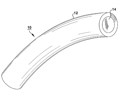
Referring now to the Figures, a front perspective view of a backer rod 10 is
illustrated
in Figure 1. The backer rod 10 includes an external shell or tube 12, and a
core 14. The
backer rod 10 shown in Figures 1 and 2 is of an exemplary length L1. The
backer rod can be
constructed to any proper length by one of several known methods, including
extruding or
molding the tube, and then filling the tube with an uncured material. Another
construction
method includes curing the core in a mold, and then wrapping elongated slats
or sections of
4
CA 02747908 2011-08-02
tube material around the core, and forming a joint along the longitudinal axis
of the backer
rod. Regardless of construction, Figure 3 illustrates a cross-sectional view
of the backer rod
as seen along the line 3-3 in Figure 2.
The external shell or tube 12 is constructed of a foamed plastic. The foam
plastic may
be impermeable to water. An exemplary foam plastic for the tube 12 is closed
cell low
density polyethylene. The polyethylene shell is advantageous in applications
within a joint.
When a sealant is applied within a joint and on the exterior of the tube 12,
the closed celled
feature prevents 3 point adhesion of the sealant to the shell surface during
application in a
joint, i.e., adhesion to the core surface. However, it should be understood by
others with skill
in the art that other suitable foams may be used in the practice of the
invention.
As shown in Figure 3, the tube 12 has an inner diameter d1 and an outer
diameter d2.
These diameters are to be sized according to application joint size and
movement
requirements. The inner diameter d1 of the core defines a hollow interior into
which the core
material is positioned. As discussed, the outer diameter d2 defines a flexible
contact surface
for the sealant.
A total assembly volume of the backer rod is defined by the outer diameter d2
of the
tube 12. With any specific given length L1, a total assembly volume of the
backer rod is
defined as a function of the outer diameter d2 of the tube 12, i.e., volume =
Liir(d2/2)2. The
performance of the backer rod 10 when exposed to fire is measurable several
ways, including
in regard to the total assembly volume.
Figures 1-3 illustrate the core 14 disposed within a hollow interior of the
tube 12.
The core 14 is formed of different material than the tube 12. The core
material is expandable
when exposed to fire. In a preferred embodiment, the core 14 is constructed of
an
intumescent material, such as for example, an intumescent polyurethane foam
having a
primary intumescent additive, such as expandable graphite. In one example, the
intumescent
polyurethane foam is 30% graphite. However, it should be understood by others
with skill in
the art that other suitable intumescent core materials may be used in the
practice of the present
invention.
The physical performance of the intumescent core material as a fire resistant
material
is measurable various ways. As one example, the intumescent expansion factor
is the ratio of
5
CA 02747908 2011-08-02
a material height before and after a heating, under a test condition that
allows only expansion
in the vertical direction. In a preferred embodiment, the core 14 is formed of
a material
having an intumescent expansion factor of at least 30.
Referring again to Figures 2 and 3, the physical performance of the backer rod
10 is at
least in part effected by the intumescent properties of the core 14. As
discussed, the tube 12 is
constructed of a combustible foam plastic. As such, tube 12 will disintegrate
when exposed to
fire. In contrast, the core material is expandable when exposed to fire.
Specifically, the core
material has an intumescent expansion factor sufficient to expand to a volume
beyond the
total assembly volume of the illustrated backer rod 10, as initially measured
at room
temperature before any fire exposure.
The expansion properties of the backer rod 10 are beneficial to provide fire
resistance
in an joint application. In Figure 4, a backer rod 10 is illustrated in an
exemplary application
environment in an enlarged cross-sectional view. The backer rod 10 is shown
after
installation in a compressed fit between a first construction element 20 and a
second
construction element 22. The backer rod 10 is illustrated in a pre-fire
condition, after only
partial installation. As shown, no sealant has been applied to form a finished
joint assembly.
The construction elements 20, 22 are adjacently disposed to form a
construction joint.
In general, the construction elements 20, 22 may be combustible. Specifically,
the first
element 20 is formed of a material having a first fire-resistant rating and
the second element
22 is formed of a material having a second fire-resistant rating. The first
and second fire-
resistant ratings may be the same of different. The construction elements 20,
22 may be made
of conventional materials, such as concrete or wood. As shown, a first surface
24 of the first
construction element 20 is opposing and adjacent a second surface 26 of the
first construction
element 22. In this position, the surfaces 24, 26 form a void between the
construction
elements 20, 22. The void has a width vl that is not greater than the tube 12
outer diameter d2.
As shown, the width vl is less than the tube 12 outer diameter d2. In the
practice of the
invention, the width vl can be up to 4 inches or greater.
The backer rod 10 is installed within the void for sealant and fire-resistant
purposes.
Referring again to Figure 4, the backer rod 10 is press fit into the void to a
depth hl to define a
sealant collection cavity 30 within the void. In Figure 5, the cavity 30 is
shown filled with a
6
CA 02747908 2011-08-02
sealant 40. Although the sealant level may vary, the sealant 40 is shown
filled to a level equal
to the top horizontal surfaces 32, 34 of the construction elements 20, 22.
After sealant
application, the backer rod essentially maintains a depth of hl to the top of
the tube 12, and a
distance of h2 (see Figure 5) from the bottom of the tube 12 to bottom
horizontal surfaces 36,
38 of the construction elements 20, 22.
Once cured, the sealant layer forms a bond between the backer rod 10 and the
first
surface 24, the backer rod 10 and the second surface 26, and the first surface
24 and the
second surface 26. However, the sealant does not penetrate the closed-cell
tube 12 to the
depth of the core 14. The condition illustrated in Figure 5 is in compliance
with an industry
standard pre-fire condition requirements.
The fire-resistant properties of the backer rod 10 and application assembly
are
apparent from Figure 6. The backer rod 10 and assembly of Figure 5 are shown
in a post-fire
condition. In the illustrated example, the backer rod 10 has been exposed to
fire on a side 42
(see Figure 5) opposite the sealant layer 40. The tube 12 has fully
disintegrated on the side 42
opposite the sealant layer. As shown, the tube and sealant layer on the
opposing side, i.e., the
side opposite the fire, are in essentially the same condition as the pre-fire
condition. As a
result, the portion of the tube 12 on the side opposite the fire remains at
essentially the same
depth hl after the fire.
Still referring to Figure 6, the intumescent core 14 has expanded during
exposure to
heat. As discussed, an upper and lower boundary of the sealant layer 40
remains constant
upon disintegration of the portion of the tube 14 on the side 42 opposite the
sealant layer 40.
As a result, the intumescent core 12 has expanded within the void during the
fire in a direction
away from the sealant layer 40. A fire-resistant barrier 44 within the void
has been formed
between the first element 20 and the second element 22. As shown, the core 14
has been
expanded in the fire to occupy the entire portion of the void on the side
opposite the sealant
layer 40. As discussed, the intumescent expansion factor of the core material
is at least 30.
The resultant fire-resistant barrier is an insulative char material that acts
to impede travel of
fire vertically through the void.
Another intumescent backer rod 100 of the present invention is shown in
Figures 7-9.
The backer rod is essentially the core material of the backer rod 10 of
Figures 1-3, but without
7
CA 02747908 2011-08-02
a tube or external shell. A cross-sectional view of the intumescent backer rod
100 is shown in
Figure 8, as installed in an exemplary construction application. Specifically,
Figure 8 shows
the backer rod 100 in a pre-fire condition, and press-fit between two non-
combustible
construction elements 120, 122. The backer rod 100 is installed within a void
for sealant and
fire-resistant purposes.
The backer rod 100 is press fit into the void to a depth h3 to define a
sealant collection
cavity within the void. As shown in Figure 8, the cavity is filled with a
sealant 140.
Although the sealant level may vary, the sealant 140 is shown filled to a
level equal to the top
horizontal surfaces 132, 134 of construction elements 120, 122. After sealant
application, the
backer rod 100 essentially maintains a depth of h3 to the top of the rod, and
a distance of h4
from the bottom of the rod 100 to bottom horizontal surfaces 136, 138 of the
construction
elements 20, 22.
In the cured position illustrated in Figure 8, the sealant layer forms a bond
between the
backer rod 100 and the first surface 124, the backer rod 100 and the second
surface 126, and
the first surface 124 and the second surface 126. The sealant does not
penetrate the backer
rod 100 to any depth that would affect the expansion of the backer rod 100 in
an opposing
direction.
The fire-resistant properties of the backer rod 100 and application assembly
are
apparent from the post-fie condition shown in Figure 9. In the illustrated
example, the backer
rod 100 has been exposed to fire on a side opposite the sealant layer 140. As
shown, the
sealant 140 on the side opposite the fire is in essentially the same condition
as the pre-fire
condition. Asa result, the upper most portion of the backer rod 100 on the
side opposite the
fire remains at essentially the same depth h3 after the fire. In a preferred
embodiment, the
fire-resistant rating of the first element 120 and the fire-resistant rating
of the second element
122 are each of a level such that the width V2 of the void between the
surfaces 124, 126 is
unchanged after expansion of the backer rod 100.
The intumescent rod 100 has expanded during exposure to the fire. The upper
boundary and a lower boundary of the sealant layer has remained constant upon
the backer
rod 100 exposure to fire, while the intumescent blocker rod 100 has expanded
within the void
during the fire in a direction away from the sealant layer 140. A fire-
resistant barrier 144
8
CA 02747908 2011-08-02
within the void has been formed between the first element 120 and the second
element 122.
As shown, the backer rod has been expanded to occupy the entire portion of the
void on the
side opposite the sealant layer 140. The fire-resistant layer is a mixture of
char material that
acts to impede travel of fire vertically through the void.
In practicing a method of the invention, a backer rod is selected with both
sealant and
fire resistance properties. The selected backer rod has an external shell
formed by a
combustible foam, such as closed cell plastic foam. The shell defines a total
shell volume and
a hollow interior. A core material is selected which is intumescent and may be
a polyurethane
foam. A proper amount of the core material is determined and disposed within
the hollow
interior of the external shell. The core material may be disposed in the shell
by injection
molding, and expands and sets within a short period of time, such as five
minutes at room
temperature. The proper amount of the core material is expandable beyond the
total shell
volume when the core material is exposed to fire.
While various inventive aspects, concepts and features of the inventions may
be
described and illustrated herein as embodied in combination in the exemplary
embodiments,
these various aspects, concepts and features may be used in many alternative
embodiments,
either individually or in various combinations and sub-combinations thereof.
Unless
expressly excluded herein all such combinations and sub-combinations are
intended to be
within the scope of the present inventions. Still further, while various
alternative
embodiments as to the various aspects, concepts and features of the inventions-
-such as
alternative materials, structures, configurations, methods, circuits, devices
and components,
software, hardware, control logic, alternatives as to form, fit and function,
and so on--may be
described herein, such descriptions are not intended to be a complete or
exhaustive list of
available alternative embodiments, whether presently known or later developed.
Those
skilled in the art may readily adopt one or more of the inventive aspects,
concepts or features
into additional embodiments and uses within the scope of the present
inventions even if such
embodiments are not expressly disclosed herein. Additionally, even though some
features,
concepts or aspects of the inventions may be described herein as being a
preferred
arrangement or method, such description is not intended to suggest that such
feature is
required or necessary unless expressly so stated. Still further, exemplary or
representative
9
CA 02747908 2011-08-02
values and ranges may be included to assist in understanding the present
disclosure; however,
such values and ranges are not to be construed in a limiting sense and are
intended to be
critical values or ranges only if so expressly stated. Moreover, while various
aspects, features
and concepts may be expressly identified herein as being inventive or forming
part of an
invention, such identification is not intended to be exclusive, but rather
there may be
inventive aspects, concepts and features that are fully described herein
without being
expressly identified as such or as part of a specific invention. Descriptions
of exemplary
methods or processes are not limited to inclusion of all steps as being
required in all cases, nor
is the order that the steps are presented to be construed as required or
necessary unless
expressly so stated.