Language selection

Search

Patent 2747915 Summary

Third-party information liability

Some of the information on this Web page has been provided by external sources. The Government of Canada is not responsible for the accuracy, reliability or currency of the information supplied by external sources. Users wishing to rely upon this information should consult directly with the source of the information. Content provided by external sources is not subject to official languages, privacy and accessibility requirements.

Claims and Abstract availability

Any discrepancies in the text and image of the Claims and Abstract are due to differing posting times. Text of the Claims and Abstract are posted:

  • At the time the application is open to public inspection;
  • At the time of issue of the patent (grant).
(12) Patent: (11) CA 2747915
(54) English Title: CORNER SEAL DEVICE
(54) French Title: DISPOSITIF D'ETANCHEITE DE COIN
Status: Granted
Bibliographic Data
(51) International Patent Classification (IPC):
  • B60J 10/21 (2016.01)
  • B60P 3/34 (2006.01)
(72) Inventors :
  • KSIEZOPOLSKI, EDWIN E. (United States of America)
  • NEWHOUSE, NORMAN L. (United States of America)
(73) Owners :
  • LIFETIME INDUSTRIES, INC. (United States of America)
(71) Applicants :
  • LIFETIME INDUSTRIES, INC. (United States of America)
(74) Agent: MILTONS IP/P.I.
(74) Associate agent:
(45) Issued: 2013-05-07
(22) Filed Date: 2011-08-02
(41) Open to Public Inspection: 2012-02-03
Examination requested: 2011-08-02
Availability of licence: N/A
(25) Language of filing: English

Patent Cooperation Treaty (PCT): No

(30) Application Priority Data:
Application No. Country/Territory Date
12/849,411 United States of America 2010-08-03

Abstracts

English Abstract

A corner seal device for use in combination with wiper seals used in slide-out rooms in recreational vehicles. The corner seal device has a first generally horizontal surface and a second generally vertical surface meeting to form a corner. A third surface extends obliquely from the first surface and has at least some portion that is above the first surface. An end wall may be used to connect the third surface to the second surface. The corner seal device may also be used with a wiper seal having an inner shelf that extends over the third surface of the corner seal device. The inner shelf may also have a C- channel at the end that covers the upper most portion of the third surface of the corner seal device.


French Abstract

Un dispositif d'étanchéité de coin à utiliser en combinaison avec les joints racleurs employés pour les rallonges escamotables des véhicules récréatifs. Le dispositif d'étanchéité de coin comprend une première surface généralement horizontale et une deuxième surface généralement verticale qui se rencontrent pour former un coin. Une troisième surface s'élève de façon oblique à partir de la première surface et au moins une partie de sa surface dépasse la première surface. Une paroi peut être utilisée pour rattacher la troisième surface à la deuxième surface. Le dispositif d'étanchéité de coin peut également être utilisé avec un joint racleur qui comprend une portion intérieure qui s'étend par-dessus la troisième surface du dispositif. La partie intérieure peut par ailleurs comprendre un canal en forme de C à son extrémité couvrant la partie supérieure de la troisième surface du dispositif d'étanchéité de coin.

Claims

Note: Claims are shown in the official language in which they were submitted.


CLAIMS:
1. A corner seal device for use in combination with edge seals useful in
openings for
a slide-out room in mobile living quarters, said corner seal device
comprising:
a first generally horizontal surface;
a second generally vertical surface, the horizontal and vertical surfaces
being
contiguous at one end to define a corner; and
a third surface extending obliquely outwardly from said first surface, said
third
surface including a portion located above said first horizontal surface, said
third surface
being connected to said second surface for some portion above said first
horizontal
surface.


2. A corner seal device as claimed in claim 1, wherein an end wall extends
from said
second surface and is connected to said third surface, said end wall having a
portion above
said first horizontal surface.


3. A corner seal device as claimed in claim 2, wherein said second surface has
an
inner flange and outer flange, said flanges extending outwardly from said
second surface,
and said flanges being spaced opposite each other and said end wall connects
said third
surface and said inner flange.


4. A corner seal device as claimed in claim 3, wherein said first surface has
an inner
flange and an outer flange, said flanges extending downwardly from said first
surface.


5. A corner seal device as claimed in claim 4, wherein said first surface
includes a
ridge extending upwardly and spaced from said second surface, said ridge
extending to a
height above said corner along its entire length.


6. A corner seal device as claimed in claim 5, wherein said ridge extends onto
said
third surface.


6


7. A corner seal device as claimed in claim 6, wherein said first edge seal
extends
along said first generally horizontal surface and a second edge seal extends
along said first
generally vertical surface.


8. A corner seal device as claimed in claim 6, wherein said first edge seal is
a first
wiper seal having a substantially horizontal surface and at least one wiper
extending
therefrom for interfacing with a slide-out room, said first wiper seal having
an upwardly
extending inner shelf extending obliquely upward from said horizontal surface
on said first
wiper seal, said inner shelf overlying said third surface of said corner seal
device.


9. A corner seal device as claimed in claim 8, wherein said inner shelf
includes a C-
shaped channel that covers said upper-most portion of said third surface.


10. A corner seal device comprising:
a first generally horizontal surface;
a second generally vertical surface, the horizontal and vertical surfaces
being
contiguous at one end to define a corner; and
a third surface extending obliquely outwardly from said first surface, said
third
surface including a portion located above said first horizontal surface.


11. A corner seal device as claimed in claim 10, wherein said third surface is

contiguously connected to said second surface.


12. A corner seal device as claimed in claim 11, wherein said third surface is

connected to said second surface with an end wall.


13. A corner seal device as claimed in claim 12, wherein said second surface
has an
inner flange and outer flange, said flanges extending outwardly from said
second surface,
and said flanges being spaced opposite each other and said end wall connects
said third
surface and said inner flange.


7


14. A corner seal device as claimed in claim 13, wherein said first surface
has an inner
flange and an outer flange, said flanges extending downwardly from said first
surface.


15. A corner seal device as claimed in claim 14, wherein said first surface
includes a
ridge extending upwardly and spaced from said second surface.


16. A corner seal device as claimed in claim 15, wherein said ridge extends
onto said
third surface.


8

Description

Note: Descriptions are shown in the official language in which they were submitted.


CA 02747915 2011-08-02

CORNER SEAL DEVICE
BACKGROUND OF THE INVENTION

[0001] Slide out rooms are common in recreational vehicles as a way to
increase the
useable interior space. Resilient seals are usually placed around the opening
in the vehicle
that the slide room is disposed within. Wiper seals are a common seal used to
prevent the
leakage of wind and water into the vehicle around the slide out room. Since
the openings
that accommodate the rooms are usually rectangular, the seals will meet at the
corners.
Making a tight leak proof connection in the corners is difficult, especially
with wiper
seals, because the seals have to be flexible enough to accommodate movement of
the slide
out room. In each corner there is a potential for leakage of water, wind, and
also light.
[0002] There is a need for a device that will prevent the entrance of light,
wind, and
rain through the corners where the seals meet. Such a device should be easily
installed
and not interfere with the present method of sealing slide out rooms.

SUMMARY OF THE INVENTION
[0003] The present invention relates to a corner seal device that is useful
for seals
typically used with slide out rooms used in recreational vehicles. The corner
seal device
has a first generally horizontal surface and a second generally vertical
surface that are
contiguous at one end to define a corner. A third surface extends obliquely
outwardly
from the first surface. The third surface has a portion located above the
first horizontal
surface and connected to the second surface for some portion above the first
horizontal
surface.

[0004] The third surface may have an end wall that extends from the second
surface
and is connected to the third surface. At least a portion of the end wall
extends above the
first horizontal surface.

[0005] In another aspect of the invention, inner and outer flanges extend
outwardly
from the first surface and the flanges are spaced opposite each other. Flanges
may also
extend from the second surface.

1


CA 02747915 2011-08-02

[0006] The corner seal device of this invention may also be used in
combination with
a first wiper seal having a substantially horizontal surface including at
least one wiper
extending therefrom for interfacing with a slide-out room. The first wiper
seal has an
upwardly extending inner shelf that extends obliquely upwardly from its
horizontal
surface. The inner shelf of the first wiper seal overlies the third surface of
the corner seal
device. The inner shelf may also include a C-shaped channel that covers the
upper most
portion of the third surface.

BRIEF DESCRIPTION OF THE DRAWINGS

[0007] FIG. 1 is a perspective view of a recreational vehicle with a slide out
room in
an extended position;

[0008] FIG. 2 is a perspective view of the recreational vehicle shown in FIG.
1 with
the slide out room removed to show the opening in which the room fits;

[0009] FIG. 3 is a perspective view of the corner seal having a raised line of
material
to form the ridge;

[0010] FIG. 4 is a perspective view of the corner seal having an angled ridge;

[0011] FIG. 5 is a perspective enlarged view of the wiper seals as they are
assembled
onto the corner seal in the lower right corner inside the circle labeled 5 in
FIG. 2;

[0012] FIG. 6 is a view of the corner seal assembly shown in FIG. 5 as viewed
from
inside the vehicle;

[0013] FIG. 7 is a view looking from the center of the opening toward the
lower right
corner seal assembly shown in FIGS. 5 and 6;

[0014] FIG. 8 is a front view of the corner seal assembly shown in FIGS. 5, 6
and 7 as
viewed from the outside of the recreational vehicle looking inward;

[0015] FIG. 9 is a perspective view of the corner seal assembly being used in
combination with a wiper seal having an inner shelf covering the third surface
of the
corner seal device; and

[0016] FIG. 10 is sectional view of the assembly shown in FIG. 9.
2


CA 02747915 2011-08-02

DETAILED DESCRIPTION OF THE INVENTION

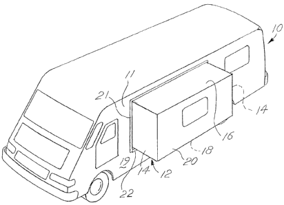
[0017] FIG. 1 shows a recreational vehicle 10 having a slide out room 12
incorporated
within the vehicle 10. The vehicle has a sidewall 11 having a rectangular
opening 13 in
which the slide out room 12 is placed. The vehicle sidewall 11 has an inner
surface 17
that faces the interior of the vehicle 10 and an outer surface 19 defining the
exterior of the
vehicle 10. The opening 13 has edge surfaces 15 that span between the inner
surface 17 of
the vehicle sidewall 11 and the outer surface 19 of the vehicle sidewall 11.
The slide out
room has sidewalls 14, a roof 16, a floor 18, and an outer wall 20. The slide
out room 12
has a first extended position shown in FIG. 1, and a fully retracted second
position in
which the outer wall 20 is flush with the vehicle sidewall 11. The slide out
room 12 is
moveable between its first and second positions.

[0018] For the slide out room 12 to function there must be some space between
the
edge surfaces 15 of the opening 13 and the room 12 itself. Wiper seals 21, 22
have wipers
23 typically placed around the perimeter of the opening to prevent the leakage
of air,
water, and light around the slide out room 12 into the interior of the
vehicle. Other types
of edge seals may be used in place of the wiper seals 21, 22 to serve the same
function.
[0019] The corner seal device 30 of this invention is designed to prevent the
leakage
of water in the lower corners of the opening 13 where the seals 21, 22 meet.
FIG. 2 shows
a perspective view of a first embodiment of the corner seal 30. The corner
seal has a first
generally horizontal surface 32 and a second generally vertical surface 34. An
inner
flange 35 and an outer flange 37 extend downwardly from the first surface 32.
An inner
flange 39 and an outer flange 41 extend outwardly from the second surface. The
first
surface 32 and second surface 34 meet to define a corner 36. A third surface
38 extends
obliquely outward from the first surface 32 so that at least a portion of the
surface extends
above the first surface 32. An end wall 42 extends from the third surface 38
and connects
to the inner flange 39. A ridge 43 on the first surface 32 extends upwardly
and continues
onto the third surface 38. The ridge may be an angled ridge 43, as shown in
FIG. 4, or can
be simply a raised line of material such as the ridge 43' shown in FIG. 3. The
ridge 43' is
spaced from the second surface 34 by a fixed distance.

3


CA 02747915 2011-08-02

[0020] The corner seal device 30 of this invention is typically used in a
matched set
with one device 30 in each lower corner of an opening 13, each being a mirror
opposite of
the other device 30. A corner seal device 30 is installed in each corner with
an adhesive
below the first and second surfaces 32, 34 where the device 30 contacts the
edge surfaces
15 of the opening. The flanges 35, 37, 39, 41 straddle the vehicle sidewall 11
and help
position the device 30 so that it is properly aligned within the opening 13.
The third
surface 38 is placed so that it is behind the inner surface 17 of the vehicle
sidewall 11.
Wiper seals 21, 22 that are often used to seal such openings 13 have flanges
50 that
straddle the vehicle sidewall 11. The flanges 50 of the vertical wiper seal 21
straddle the
flanges 39, 41 of the device 30. An adhesive strip 51 is typically placed on
the outermost
flange 50 of the seal. This adhesive strip 51 secures the flange 50 of the
seal 21 to the
outer surface 19 of the vehicle sidewall 11 and to the outer flange 37 of the
device 30.
The vertical seal 21 may touch or nearly touch the top of the ridge 43, but
the seal 21 does
not extend below the ridge 43. This leaves a gap 54 below the seal 21. The
horizontal
wiper seal 22 also straddles the vehicle sidewall 11. The flanges of the
horizontal wiper
seal 22 stop at the ridge 43 and typically no part of the horizontal wiper
seal 22 extends
beyond the ridge 43.

[0021] Another embodiment of the seal is shown in FIGS. 9 and 10. In this
embodiment the wiper seal 22' has an upwardly extending inner shelf 56 that
extends from
a substantially horizontal surface 58 on the wiper seal 22'. The inner shelf
56 extends
obliquely into the interior of the recreational vehicle 10. The inner shelf 56
has a C-
shaped channel 60 at its upper-most portion. This C-shaped channel 60 covers
the upper-
most portion of the third surface 38.

[0022] When the vehicle 10 is exposed to rain and the room 12 is extended,
water may
potentially leak into the vehicle 10 when it runs down the seals 21. The
horizontal seal 22
will prevent water from entering the vehicle 10 from below the room 12 for
most of the
distance between the corners of the opening 13. With the corner seal device 30
installed,
potential leakage from the corners of the opening 13 is prevented. As water
runs down the
vertical seal 21 it will reach the ridge 43. The ridge 43 will prevent water
from entering
behind the horizontal seal 22. As water reaches the ridge 43, the slope of the
ridge 43 is
downward toward the corner 36. Water will run outward away from the center of
the

4


CA 02747915 2011-08-02

opening and into the corner 36 of the corner seal device 30. The sloped third
surface 38
prevents water from running inward from the outside of the vehicle 10 to the
inside of the
vehicle. The third surface 38 is sloped downwardly toward the exterior of the
vehicle 10.
As water collects in the corner 36, it will tend to run along the ridge across
the first surface
32. When water reaches the third surface 38, it will be unable to rise above
the height of
the third surface 38. Therefore, the water will run out of the gap 54.

[0023] In the embodiment shown in FIGS. 9 and 10, the inner shelf 56 will
provide
further protection from water leaking into the vehicle 10. The inner shelf 56
extends the
entire length of the wiper seal 22'. As water reaches the inner shelf 56
between the
corners of the opening 13, the water will be unable to rise above the inner
shelf 56 before
it runs out of the corners 36 of the corner seal device 30.

[0024] The corner seal device also prevents the entry of sunlight through the
corners
of the opening 13 where the seals 21, 22 meet. Customers who purchase
recreational
vehicles 10 containing slide out rooms 12 generally perceive light leaking
through the
corners of the slide out room 12 to be a defect. The third surface 38 prevents
light from
entering through the gap 54. As light enters the gap 54, it will be unable to
rise above the
third surface 38 and a customer inside the vehicle 10 will not see light from
the exterior
entering the vehicle through the corner.

[0025] This invention is not limited to the details above, but may be modified
within
the scope of the following claims.


Representative Drawing
A single figure which represents the drawing illustrating the invention.
Administrative Status

For a clearer understanding of the status of the application/patent presented on this page, the site Disclaimer , as well as the definitions for Patent , Administrative Status , Maintenance Fee  and Payment History  should be consulted.

Administrative Status

Title Date
Forecasted Issue Date 2013-05-07
(22) Filed 2011-08-02
Examination Requested 2011-08-02
(41) Open to Public Inspection 2012-02-03
(45) Issued 2013-05-07

Abandonment History

There is no abandonment history.

Maintenance Fee

Last Payment of $263.14 was received on 2023-05-02


 Upcoming maintenance fee amounts

Description Date Amount
Next Payment if small entity fee 2024-08-02 $125.00
Next Payment if standard fee 2024-08-02 $347.00

Note : If the full payment has not been received on or before the date indicated, a further fee may be required which may be one of the following

  • the reinstatement fee;
  • the late payment fee; or
  • additional fee to reverse deemed expiry.

Patent fees are adjusted on the 1st of January every year. The amounts above are the current amounts if received by December 31 of the current year.
Please refer to the CIPO Patent Fees web page to see all current fee amounts.

Payment History

Fee Type Anniversary Year Due Date Amount Paid Paid Date
Request for Examination $800.00 2011-08-02
Application Fee $400.00 2011-08-02
Final Fee $300.00 2013-02-22
Maintenance Fee - Patent - New Act 2 2013-08-02 $100.00 2013-06-17
Maintenance Fee - Patent - New Act 3 2014-08-04 $100.00 2014-07-03
Maintenance Fee - Patent - New Act 4 2015-08-03 $100.00 2015-05-25
Maintenance Fee - Patent - New Act 5 2016-08-02 $200.00 2016-07-12
Maintenance Fee - Patent - New Act 6 2017-08-02 $200.00 2017-06-30
Maintenance Fee - Patent - New Act 7 2018-08-02 $200.00 2018-04-20
Maintenance Fee - Patent - New Act 8 2019-08-02 $200.00 2019-04-15
Maintenance Fee - Patent - New Act 9 2020-08-03 $200.00 2020-08-10
Maintenance Fee - Patent - New Act 10 2021-08-03 $255.00 2021-08-03
Maintenance Fee - Patent - New Act 11 2022-08-02 $254.49 2022-07-22
Maintenance Fee - Patent - New Act 12 2023-08-02 $263.14 2023-05-02
Owners on Record

Note: Records showing the ownership history in alphabetical order.

Current Owners on Record
LIFETIME INDUSTRIES, INC.
Past Owners on Record
None
Past Owners that do not appear in the "Owners on Record" listing will appear in other documentation within the application.
Documents

To view selected files, please enter reCAPTCHA code :


To view images, click a link in the Document Description column. To download the documents, select one or more checkboxes in the first column and then click the "Download Selected in PDF format (Zip Archive)" or the "Download Selected as Single PDF" button.

List of published and non-published patent-specific documents on the CPD .

If you have any difficulty accessing content, you can call the Client Service Centre at 1-866-997-1936 or send them an e-mail at CIPO Client Service Centre.


Document
Description 
Date
(yyyy-mm-dd) 
Number of pages   Size of Image (KB) 
Maintenance Fee Payment 2020-08-10 1 33
Maintenance Fee Payment 2021-08-03 1 33
Maintenance Fee Payment 2022-07-22 1 33
Maintenance Fee Payment 2023-05-02 1 33
Abstract 2011-08-02 1 17
Description 2011-08-02 5 235
Claims 2011-08-02 3 88
Drawings 2011-08-02 5 130
Representative Drawing 2012-01-25 1 11
Cover Page 2012-01-30 2 44
Cover Page 2013-04-17 1 41
Change of Agent 2017-07-06 3 78
Office Letter 2017-07-12 1 22
Office Letter 2017-07-12 1 24
Assignment 2011-08-02 4 97
Maintenance Fee Payment 2019-04-15 1 33
Correspondence 2013-02-22 1 29