Note: Descriptions are shown in the official language in which they were submitted.
CA 02748451 2014-12-19
MODULAR DIGITAL CAMERA
BACKGROUND
[0002] Digital cameras include a series of functional components such
as lenses,
optical filters, one or more electronic image sensor arrays, electronic
circuits to capture,
process and store images from the image sensor array, internal or external
memory devices to
store and transfer image files, power supplies and a display system to preview
the captured
images. These components are typically integrated and interdependent, from
each of an
optical, electronics and physical perspective. In many instances, external
lenses and power
supplies may be attached to and removed from the camera. But the remaining
components are
typically permanently integrated into a main framework or housing without any
practical
ability to be removed and replaced. As a consequence, the performance and
functionality of
these cameras are limited by the least advanced component or the first
component to
malfunction. In addition, these cameras are not upgradeable with updated
technology and
must instead be replaced in their entirety in order to obtain the benefit of
technological
improvements in only a single component part. Additionally, due to the limited
configurability associated with conventional cameras, they are typically
suitable for a limited
range of applications and contexts. For example, such cameras are generally
suited for either
still or motion photography, but not both. As a result, users who want to
shoot in a variety of
contexts and for a variety of applications often need to purchase multiple
cameras to achieve
desired results.
100031 Thus, notwithstanding the various digital camera options
available in the
art, there remains a need for a camera system that is fully customizable by
the user, and
which overcomes the limitations discussed above.
-
CA 02748451 2011-06-27
WO 2010/078173
PCT/US2009/069316
SUMMARY
J0004] The present disclosure provides a fully modular digital camera
system. In
certain embodiments, for example, the digital camera system can advantageously
be a digital
still and motion camera (DSMC) which can be optionally configured for both
still and motion
shooting. In various embodiments, the camera system can be either a still,
motion, or
still/motion combination digital camera. Each module may be removed from the
system and
replaced, for example, by an upgraded technology module, while preserving the
functionality
of the remainder of the system. This interchangeable nature of the modular
design allows a
camera owner to replace various components as they are upgraded and improved,
rather than
having to replace the entire camera system.
10005] In addition, the modules may be disconnected and reassembled by
the user
to rapidly change the physical configuration of the system. The various
electronics modules
may be connected to each other or stacked in any sequence and in a wide
variety of
geometries, to enable reconfiguration of the system to suit the user's
preference.
100061 For example, the modular camera system may be assembled in a
DSLR
mode such as for use with a handle such as a bottom grip handle. The system
may be
disassembled and reassembled in an electronics news gathering (ENG) mode
(e.g., for use
with a shoulder mount), or into a studio configuration, such as for use on a
tripod, dolly, or
crane. Reconfiguration can be accomplished to move the center of gravity
forward or
backward along the viewing axis, and any of a variety of support hardware such
as grips,
bars, or frames may be readily connected to the modular system, as may be
appropriate for
the assembled configuration.
100071 The modular camera system comprises a sensor module or "brain"
in
certain embodiments, and the terms sensor module and brain module are used
interchangeably herein. The brain module preferably additionally comprises
digital signal
processing electronics and may further comprise an interface for removably
receiving a
functional module. The functional module may comprise any one or more of a
recording
module, a power module, an in/out module, a user interface module, lens mount,
or some
other type of functional module.
-2-
CA 02748451 2011-06-27
WO 2010/078173 PCT/US2009/069316
[0008] There is provided in accordance with one aspect of the present
disclosure,
a modular digital camera. The camera comprises a sensor module, having a first
interface. A
power module is provided having a second and third interface, and a recording
module is
provided, having a fourth and fifth interface. The first interface is
functionally engageable
with at least any of the second and fourth interfaces. In this manner, the
power module,
recording module, and other optional modules may be stacked in any order on
the sensor
module. In certain embodiments, the third interface is functionally engageable
with the fourth
interface, and the second interface is functionally engageable with the fifth
interface.
[0009] The power module includes a recording bus extending between the
second
and third interface, for transmitting motion picture image data through the
power module.
The recording module includes a power bus extending between the fourth and
fifth interface,
for transmitting power through the recording module.
[0010] Preferably, the modular camera additionally comprises an in/out
module
having a sixth and seventh interface. The sixth interface is engageable with
at least the first
interface, and the seventh interface is engageable with at least the second
interface. In this
manner, the power module, recording module and in/out module may be stacked in
any order
on the sensor module.
[0011] Preferably, a user interface module is additionally provided.
The user
interface module may include an eighth interface, which may be engageable with
any other
interface in the system. In one implementation of the disclosure, the user
interface module
comprises an eighth interface which is engageable with any of the third and
fifth interface.
The user interface may additionally comprise a transceiver for wireless
communication with
other devices, such as the sensor module. The user interface may therefore be
functionally
associated with but physically detached from the modular camera system.
[0012] In one implementation, the modular camera further comprises at
least a
second power module, the second power module having a ninth and tenth
interface. The
second power module preferably comprises a recording bus extending between the
ninth and
tenth interface, for transmitting motion picture image data through the second
power module.
The second power module preferably also comprises a control bus extending
between the
ninth and tenth interface, for transmitting control signals through the second
power module.
-3-
CA 02748451 2011-06-27
WO 2010/078173 PCT/US2009/069316
[0013] The module camera system preferably additionally comprises a
lens mount
module, releasably connectable to the sensor module. A digital signal
processor may reside in
the sensor module.
10014] The sensor module may be directly or indirectly engageable with
the other
modules. For example, in certain embodiments, the first interface is
indirectly functionally
engageable with any of the second and fourth interfaces via a releasably
attachable adapter
plate. In some other embodiments, the first interface is indirectly
functionally engageable
with any of the second and fourth interfaces via one or more dummy modules.
[0015] In accordance with a further aspect of the present disclosure,
there is
provided a modular camera. The camera comprises a sensor module having a first
bus
segment, a recording module having a second bus segment, and a power module
having a
third bus segment. Each of the modules is releasable connectable to any other
of the modules,
such that every assembled configuration of the modules places the bus segments
in
communication with each other in a manner that permits functional electrical
communication
among each of the modules.
[0016] The modular camera system preferably additionally comprises an
in/out
module having a fourth bus segment, that is directly connectable with any of
the other bus -
segments. The sensor module of certain embodiments can be directly or
indirectly releasably
connectable to any other of the modules. For example, the sensor module can be
indirectly
releasably connectable to any other of the modules via one or more of a
relesably attachable
adapter plate, dummy module, or the like.
100171 In accordance with a further aspect of the present disclosure,
there is
provided a modular, convertible camera. The camera comprises a sensor module,
a recording
module, a power module, and a user interface module. Each module is directly
or indirectly
releasably connectable to the sensor module in a first construct to produce a
camera having
an ENG configuration, and at least one or two and preferably each module maybe
disconnected and reassembled into a second construct, having a DSLR
configuration. The
camera may further include an in/out module.
[0018] In accordance with a further aspect of the present disclosure,
there is
provided a modular convertible camera system. The system includes a sensor
module, a
-4-
CA 02748451 2011-06-27
WO 2010/078173
PCT/US2009/069316
recording module, a power module and a user interface module. Each module is
directly or
indirectly releasably connectable to the sensor module in a first construct to
produce a camera
having an ENG configuration, and at least one or two and preferably each
module may be
disconnected and reassembled into a second construct having a studio
configuration.
100191 In accordance with a further aspect of the present disclosure,
there is
provided a modular, convertible camera. The camera comprises a sensor module,
a recording
module, a power module, and a user interface module. Each module is directly
or indirectly
releasable connectable to the sensor module in a first construct, to produce a
camera having a
studio configuration, and at least one or two and preferably each module may
be disconnected
and reassembled into a second construct having a DSLR configuration.
100201 In accordance with a further aspect of the present disclosure,
there is
provided a modular, multi-component convertible camera. The modular camera
comprises a
sensor module, a recording module, a power module, and a user interface
module. Each
module is directly or indirectly releasably connectable to the sensor module
in a first
construct to produce a camera having an ENG configuration, and each module may
be
disconnected and reassembled into a second construct having a DSLR
configuration, and
each module may be disconnected and reassembled into a third construct having
a studio
configuration.
100211 In accordance with a further aspect of the present disclosure,
there is
provided a modular camera subassembly. The subassembly comprises a sensor
module,
having a sensor, digital signal processing electronics, and a back focal
distance of no more
than about 16 mm. The sensor module is configured for connection to an
external recording
module and an external power module.
100221 There is provided in accordance with a further aspect of the
present
disclosure a module camera system configured for operation with any of a
plurality of lenses
having different focal lengths. The system comprises a sensor module, having
an interface for
removably receiving a lens mount module. At least a first and a second lens
mount module
are removably connectable to the interface, each lens mount module having a
different focal
length. Each lens mount module focal length is selected so that it can be
mounted to the
sensor module and added to the back focal length of the modular camera system,
to produce
-5-
CA 02748451 2011-06-27
WO 2010/078173
PCT/US2009/069316
an overall focal length of the system. The overall focal length of the system
may be any of a
variety of lengths, including 17 mm, 35 mm, 46 mm, 48 mm, 52 mm, or other
focal length. In
one implementation of the disclosure, the back focal length is no more than
about 16 mm.
100231 The modular camera system preferably additionally comprises
digital
signal processing electronics in the sensor module. The sensor module may
further comprise
an interface for removably receiving a functional module. The functional
module may
comprise any one or more of a recording module, a power module, an in/out
module, and a
user interface module.
[0024] In accordance with a further aspect of the present disclosure,
there is
provided a modular camera comprising a camera body having an image sensor and
a first bus
segment. The modular camera can include a first module having a second bus
segment, and a
second module having a third bus segment. In certain embodiments, each of the
camera body,
the first module and the second module are releasably connectable to each
other. At least one
assembled configuration of the modules places the bus segments in
communication with each
other in a manner that permits functional electrical communication among each
of the
modules in some embodiments. in some embodiments, every assembled
configuration of the
modules places the bus segments in communication with each other in a manner
that permits
functional electrical communication among each of the modules. According to
some
embodiments, the camera body is releasably connectable to each of the first
and the second
module via a releasably connectable adapter plate.
100251 The modular camera may include a variety of modules. In some
embodiments, the first module comprises a recording module and the second
module
comprises a power module. In one embodiment, the modular camera further
comprises a third
module having a fourth bus segment.
100261 In certain embodiments, each of the first, second and third bus
segments
can include a power bus, for example. Additionally, each of the first, second
and third bus
segments comprises a SATA bus in some embodiments. In some embodiments, each
of the
first, second and third bus segments comprises a PCI Express bus.
100271 There is provided in accordance with one aspect of the present
disclosure,
an image capturing apparatus. The image capturing apparatus can include an
electronic image
-6-
CA 02748451 2011-06-27
WO 2010/078173 PCT/US2009/069316
sensor having a plurality of sensor elements and, in certain embodiments, the
sensor elements
detect light and provide an output representative of the detected light. The
image capturing
apparatus includes a digitizing module that converts the output representative
of the detected
light into a digital format. The image capturing apparatus can further include
a processor
configured to communicate the digitized sensor output onto a digital bus. In
addition, the
image capturing apparatus can include a housing that contains the electronic
image sensor,
the digitizing module, and the processor. The housing can include a bus
interface configured
to electronically connect the digital bus to a detachable module. In certain
embodiments, the
housing also includes an engagement mechanism configured to physically fasten
the housing
with the detachable module. In certain embodiments, the digitized sensor
output is
compressed prior to communication on the digital bus.
100281 A modular camera is provided in accordance with certain aspects
of the
disclosure. The modular camera can include a camera body comprising an image
sensor and a
first module interface. The first module interface includes a mating portion
and an electrical
coupling portion, for example. The modular camera can further include a
plurality of modules
each releasably and functionally engageable with the camera body and with each
of the other
of the plurality of modules. Each of the plurality of modules comprises a
first interface in
certain embodiments. The first interface includes a mating portion and an
electrical coupling
portion. The mating portion of the first interface can be releasably
mechanically matable with
the mating portion of the first module interface. Additionally, the electrical
coupling portion
of the first interface can be electrically couplable with the electrical
coupling portion of the
first module interface so as to communicate signals between the camera body
and the
module. Each of the plurality of modules can also include a second interface
which may
include a mating portion and an electrical coupling portion. The mating
portion of the second
interface can be releasably mechanically matable with the mating portion of
the first interface
of each of the other of the plurality of modules, for example. The electrical
coupling portion
of the second interface can be configured to be electrically couplable with
the electrical
coupling portion of the first interface of each of the other of the plurality
of modules. In
certain embodiments, each of the modules also includes a bus segment for
communicating
signals between the first interface and the second interface.
-7-
CA 02748451 2011-06-27
WO 2010/078173 PCT/US2009/069316
[0029] In certain embodiments, the first interface of each of the
plurality of
modules is located on a first side of a housing of the corresponding module.
The second
interface of each of the plurality of modules can be located on a second side
of the housing of
the corresponding module, wherein the second side is opposite the first side.
100301 In certain embodiments, in an assembled configuration, a first
module of
the plurality of modules is attached to the camera body, and the remaining
modules of the
plurality of modules are arranged in a stack extending from the first module.
In some
embodiments, the a first module of the plurality of modules comprises a
recording module. A
second module of the plurality of modules comprises a power module in some
embodiments.
In certain embodiments, a second module of the plurality of modules comprises
a user
interface module configured for wireless communication with the camera body.
In certain
embodiments, at least one module of the plurality of modules comprises a
cooling unit.
[0031] The camera body comprises a releasably attachable adapter plate
including
the first module interface in some embodiments.
[0032] The bus segment can include a recording bus for transmitting
image data
between the first interface and the second interface. The bus segment can also
include a
power bus for transmitting power between the first interface and the second
interface.
10033] In some embodiments, the camera includes a lens mount module can
be
releasably connectable to a lens mount interface of the camera body. The
camera can also
include a handle module can be releasably connectable to an interface of the
camera body.
The camera body further comprises a second module interface releasably and
functionally
engageable with each of the plurality of modules in certain embodiments.
100341 According to certain aspects of the disclosure, a module adapted
to
connect with a modular image capturing apparatus is provided. The module can
include a
housing and can further include a first bus interface having a first type of
electrical
connection located on a first side of the housing. The first bus interface can
also include a
second bus interface having a second type of electrical connection located on
a side of the
housing opposite the first side of the housing. For example, the first type of
electrical
connection can be operably couplable with electrical connections of the second
type of
electrical connection. The module can further include a first engagement
interface of a first
-8-
CA 02748451 2011-06-27
WO 2010/078173
PCT/US2009/069316
type located on the first side of the housing and a second engagement
interface of a second
type located on the second side of the housing. The engagement interfaces of
the first type
can be configured to fasten together with engagement interfaces of the second
type. In certain
embodiments, the first bus interface, the second bus interface, the first
engagement
component, and the second engagement component are positioned in the housing
to allow
multiple modules having the same configuration to be daisy-chained together.
[00351 In certain embodiments, the module can further include a
repeater between
the first bus interface and the second bus interface. The module can also
include an amplifier
between the first bus interface and the second bus interface in certain
embodiments. In certain
embodiments, the first bus interface and the second bus interface are Serial
ATA compatible,
for example. In some other embodiments, the first bus interface and the second
bus interface
are Peripheral Component Interconnect Express compatible. In certain
embodiments, the first
bus interface and the second bus interface are compatible with at least two
high bandwidth
buses. For example, the at least two high bandwidth buses are Serial ATA and
Peripheral
Component Interconnect Express buses. In some embodiments, the first bus
interface and the
second bus interface are compatible with at least three high bandwidth buses.
The at least
three high bandwidth buses are each capable of at least about 1 GB/s of data
throughput, for
example. In certain embodiments, the at least three high bandwidth buses
comprise Serial
ATA, Peripheral Component Interconnect Express, and XAUI buses. In some
embodiments,
the first bus interface and the second bus interface are further compatible
with a plurality of
support buses. For example, the plurality of support buses comprise two or
more of an Inter-
integrated circuit (I2C) bus, a Serial Peripheral Interface (SPI) bus, a 1-
Wire bus, and an
RS-232 bus, in certain embodiments.
100361 The module can include a recording bus extending between the
first bus
interface and the second bus interface, for transmitting image data through
the module. The
module can also include a power bus extending between the first bus interface
and the second
bus interface, for transmitting power through the module.
100371 An adapter module is provided in accordance with certain
aspects of the
disclosure for use with a modular camera system. The adapter module can be
configured to
connect a modular image capturing apparatus and a functional module having
incompatible
-9-
CA 02748451 2011-06-27
WO 2010/078173
PCT/US2009/069316
connections, for example. The adapter module can include a housing, for
example. The
adapter module of certain embodiments includes a first bus interface having a
first type of
electrical connection located on a first side of the housing and a second bus
interface having a
second type of electrical connection located on a side of the housing opposite
the first side of
the housing. The first type of electrical connection can be operably couplable
with an
electrical connection of a modular image capturing apparatus. The second type
of electrical
connection can be operably couplable with an electrical connection of an
expansion module
of the modular camera system. The adapter module can also include a first
engagement
interface located on the first side of the housing and a second engagement
interface located
on the second side of the housing. The first engagement interface can be of a
first type that is
configured to fasten the adapter module together with a modular image
capturing apparatus.
The second engagement interface can be of a second type that is configured to
fasten the
adapter module together with the expansion module.
100381 In certain embodiments, the first type of electrical connection
is operably
couplable with the second type of electrical connection. In some other
embodiments, the first
type of electrical interface is not operably couplable with the second type of
electrical
interface. The first type of engagement interface is not configured to fasten
together with the
second type of engagement interface in some configurations. In certain
embodiments, the first
type of engagement interface is configured to fasten together with the second
type of
engagement interface.
100391 According to yet another aspect of the present disclosure, a
modular,
convertible digital still and motion camera system is provided. The camera
system can
include a sensor module and can futher include a plurality of functional
modules each directly
or indirectly releasably connectable to the sensor module. In certain
embodiments, a first
group of least one of the plurality of functional modules can be directly or
indirectly
releasably connected to the sensor module in a first construct to produce a
camera having a
motion configuration. In certain embodiments, a second group of at least one
of the plurality
of functional modules can be directly or indirectly releasably connected to
the sensor module
in a second construct having a still configuration.
- I 0-
CA 02748451 2011-06-27
WO 2010/078173
PCT/US2009/069316
10040] In certain embodiments, the sensor module is indirectly
releasably
connectable to at least one of the plurality of functional modules via a
releasably attachable
adapter module.
100411 A variety of module configurations are possible. In certain
embodiments,
at least one functional module in the first group comprises a recording
module. In some
embodiments, at least one functional module in the first group comprises a
power module. At
least one functional module in the first group can comprise an in/out module,
for example. In
certain embodiments, at least one functional module in the second group
comprises a handle
module. The handle module can include a power source, for example. in some
embodiments
the second construct is a DSLR configuration. The first construct can be
Studio configuration
or an ENG configuration in various embodiments.
100421 In some embodiments, at least one of the functional modules in
the first
group is different from at least one of the functional modules in the second
group. In certain
embodiments, the first group comprises at least two functional modules daisy
chained
together when assembled in the first construct.
[00431 According to another aspect of the present disclosure, a method
of
distributing power in a modular camera system is provided. The method can
include
detecting, by at least one processor of a sensor module of a modular camera
system, the
presence of one or more available first power sources associated with one or
more of a
plurality of functional modules. Each of the plurality of functional module
can be directly or
indirectly attached to the sensor module, for example. A power bus extends
between the
sensor module and each of the plurality of functional modules in certain
embodiments. In
certain embodiments, the method can further include receiving, at the sensor
module and over
the input power bus, a first input power signal from one of the one or more
available first
power sources. The method can also include transmitting over the power bus, an
output
power signal to the plurality of functional modules for consumption by
electronics of the
plurality of functional modules. In certain embodiments, the method comprises
communicating to each of the one or more functional modules associated with
the one or
more available first power sources, which of the available first power sources
should be
placed on power bus.
-11-
CA 02748451 2011-06-27
WO 2010/078173 PCT/US2009/069316
[0044] In some embodiments, the one or more available first power
sources
comprise a plurality of power souces associated with a single functional
module. In one
embodiments, the single functional module comprises a quad battery pack. The
available first
power sources comprise power sources can be associated with a plurality of
functional
modules, for example. In certain embodiments, the method further comprises
selecting the
output power signal from one of the first input power signal and one or more
second input
power signals associated with a corresponding one or more available second
power sources.
In some embodiments, the one or more available second power sources comprise
an external
power source connectable to camera system via a an input port of the sensor
module. In yet
other embodiments, the one or more available second power sources comprise a
battery
housed in a handle assembly releasably connectable to the sensor module.
BRIEF DESCRIPTION OF THE DRAWINGS
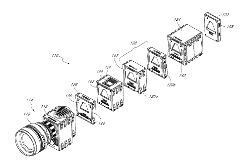
[0045] Figures I A-B are perspective exploded views of one
configuration of a
modular camera system in accordance with embodiments described herein.
[0046] Figure 1C shows a lens, lens mount module, and brain module of
the
camera system of Figure 1 in a disassembled configuration.
[0047] Figure 2 is a schematic representation of various modules in the
modular
camera system in accordance with embodiments described herein.
[0048] Figures 3A-B are perspective exploded views of another
configuration of a
modular camera system in accordance with embodiments described herein.
[0049] Figure 4 is a schematic representation of a single module in
accordance
with embodiments described herein.
100501 Figure 5 shows a rear view of the brain module of the camera
system of
Figure 1.
[0051] Figures 6A-B show front and rear views of the adapter module of
the
camera system of Figure 1.
[0052] Figures 7A-B show front and rear views of an expansion module of
the
camera system of Figure I, particularly, a recording module.
-12-
CA 02748451 2011-06-27
WO 2010/078173
PCT/US2009/069316
100531 Figure 8 shows a rear view of the user interface module of the
camera
system of Figure 1.
100541 Figures 9A-B show front and rear views of another embodiment of
an
expansion module of a camera system in accordance with embodiments described
herein.
100551 Figures 10-12 are perspective views of additional embodiments of
camera
system configurations in accordance with embodiments described herein.
DETAILED DESCRIPTION
100561 Various embodiments will be described hereinafter with reference
to the
accompanying drawings. These embodiments are illustrated and described by
example only,
and are not intended to be limiting.
System Overview
100571 Referring to Figure 1, there is schematically illustrated a
modular camera
system 10 in accordance with the present disclosure. Although the camera
system will be
primarily described herein as a motion camera system, it is to be understood
that the
principals of the present disclosure are applicable to digital still cameras,
digital video
cameras as well as digital still and motion cameras (DSMC).
100581 In addition, the description herein will be primarily directed
to the physical
electronics and optical modules of the present camera systems. However,
additional modules,
components and accessories are also contemplated in the systems of the present
disclosure.
These include, for example, any or combinations of lenses; lens mounts;
stabilization
modules or features: neutral density filters and modules containing neutral
density filters;
brain modules with or without separate electronics modules; user interface
modules; input /
output modules; various system bus configurations; recording modules; various
displays such
as LCD displays; cooling units; electronic view finders, optical view finders
and handles.
100591 The camera of the present disclosure may also be provided with
or
compatible with rails, rods, shoulder mounts, tripod mounts, helicopter
mounts, matte boxes,
follow focus controls, zoom controls, and other features and accessories known
in the art.
-13-
CA 02748451 2011-06-27
WO 2010/078173
PCT/US2009/069316
100601 The
pre-calibrated, modular aspect of camera systems provided herein
enables a user to construct a modular camera in a variety of configurations.
For example, a
first brain module may have a first, smaller sensor size. When a larger
sensor, recording area,
recording speed or the like is desired, the user may uncouple various other
functional
modules described herein from the brain module with the first sensor size, and
reassemble the
modular system using a second brain module having a second, larger sensor
size. All of the
reassembled modules with the second brain module can be automatically
calibrated for
seamless functioning without the need for extra calibration or adjustment
steps. This allows
the user to upgrade the sensor or other brain components without the need to
purchase a new
camera or camera system.
100611 The
same exchange / upgrade capability exists with respect to each of the
modules in the system of the present disclosure. Thus, the particular
technologies used in the
various modules are deemphasized in importance compared to some of the prior
art systems,
since the modules may be simply removed and replaced as upgraded technology
becomes
available. Moreover, the camera system 110 can be configured in a variety of
constructs that
can be tailored for specific uses by swapping and/or rearranging the modules
surrounding the
brain module 112 or by swapping the brain module 112 itself for another brain
module. For
example, the camera system 110 of certain embodiments can be configured for
use in a first
construct suited for still shooting (e.g., a DSLR construct), and a second
construct configured
for motion shooting (e.g., a studio or ENG construct). As another example, in
further
configurations the system can be configured in a studio construct for studio
use and portable
construct for portable use. Users can generally select from a wide variety of
different
constructs depending on the particular application. Moreover, the same same
modules,
combinations or sub-combinations of modules can be used across the various
constructs,
allowing a user to shoot in a variety of contexts without needing to purchase
context or
application specific cameras. For example, the camera system 110 according to
various
embodiments can be custom-configured an array of constructs including, without
limitation,
still, motion, portable, studio, mounted, handheld, professional, and consumer
constructs, or
any subset thereof.
-14-
CA 02748451 2011-06-27
WO 2010/078173
PCT/US2009/069316
10062] The modular camera system 110 includes a sensor and electronics
(or
brain) module 112 and lens 116. The module camera system 110 can also include
and is
configured to be functionally engagable with one or more optional modules
including at least
one recording modules 120, at least one user interface module 122, at least
one power module
124, at least one input/output module 126, and an adapter module 128. In some
embodiments, the system 110 may include more than one of each type of module,
may not
include one or more of the modules shown with respect to Figure 1.
Additionally, the system
110 may include a wide variety of other types of modules not present in Figure
1.
Brain module
100631 The image sensor contained within the brain module 112 may
comprise
any of a variety of video sensing devices, including, for example, CCD, CMOS,
vertically
stacked CMOS devices such as the FOVEONO sensor, or a multi-sensor array using
a prism
to divide light between the sensors. In some embodiments, the image sensor can
include a
CMOS device having about 12 million photocells. However, other size sensors or
sensor
technologies can also be used.
100641 In some configurations, the camera can be configured to output
video at
"2k- (e.g., 16:9 (2048 x 1152 pixels), 2:1 (2048 x 1024 pixels), etc.), "3k"
(e.g., 16:9
(3072x1728 pixels), 2:1 (3072x1536 pixels), etc.), "4k" (e.g., 4,096 x 2,540
pixels, 16:9
(4096x2304 pixels), 2:1 (4096x2048), etc.), "4.5k- horizontal resolution, Quad
HD (e.g.,
3840x2160 pixels), "5k" (e.g., 5120x2700) horizontal resolution, or greater
resolutions. As
used herein, in the terms expressed in the format of xk (such as 2k and 4k
noted above), the
"x" quantity refers to the approximate horizontal resolution. As such, "4k"
resolution
corresponds to about 4000 or more horizontal pixels and "2k" corresponds to
about 2000 or
more pixels.
10065] The sensor can range from as small as about 0.5" (8 mm), 2/3",
S35 (eine),
35 mm full frame still and 645, but it can be at least about 1.0 inches, 6 cm
x 17 cm or larger.
In one series of brain modules, sensors are contemplated having sizes of at
least about 10.1 x
5.35 mm; 24.4 x 13.7 mm; 30 x 15 mm; 36 x 24 mm; 56 x 42 mm and 186 x 56 mm.
Additionally, the image sensor can be configured to provide variable
resolution by selectively
-15-
CA 02748451 2011-06-27
WO 2010/078173
PCT/US2009/069316
outputting only a predetermined portion of the sensor. For example, the sensor
and/or the
image processing module can be configured to allow a user to identify the
resolution of the
image data output.
100661 The brain module 112 of certain embodiments may be referred to
as the
"brain" of the camera system 110 for example. Thus, as described herein, users
can select
different brain modules 112 or "brains" around which they can build camera
systems having
a multitude of possible configurations.
[0067] The camera can also be configured to scale down the resolution,
such as by
downsampling and subsequently processing the output of the sensor to yield
video output at
2K, 1080p, 720p, or any other resolution. For example, the image data from the
sensor can be
"windowed", thereby reducing the size of the output image and allowing for
higher readout
speeds. Alternatively, brain modules having different sensor sizes may be
exchanged
depending upon the desired effect. Additionally, the camera can be configured
to upsample
the output of the sensor to yield video output at higher resolutions. In some
embodiments, the
sensor can include a Bayer pattern filter. As such, the sensor, by way of its
chipset (not
shown) outputs data representing magnitudes of red, green, or blue light
detected by
individual photocells of the image sensor. Any of a variety of sensor sizes or
other sensor
characteristics may be utilized in the modular camera system of the present
disclosure.
100681 The electronics contained in the sensor and electronics module
112 are
digital signal processing electronics for processing image data captured by
the sensor. The
brain module may be configured to deliver any of a variety of desired
performance
characteristics. For example, light received by the sensor may be converted
into raw digital
image data at a rate of at least about 23 frames per second (fps), wherein the
raw data is
compressed and recorded at a rate of at least about 23 (fps) into the
recording module 120. In
various embodiments, frame rates of from about 1 fps to about 250 fps or more
can be
achieved. For example, the frame rate may depend on the resolution setting. In
some
embodiments, the camera 10 is configured for frame rates of from between about
1 fps and
about 100 fps in a "5k" resolution mode, from about I and about 125 fps in a
"4k" resolution
mode, from about 1 and about 125 fps in a quad HD mode, from about 1 and about
160 fps in
a "3k" resolution mode, and from about 1 and about 250 fps in a "2k"
resolution mode. The
-16-
CA 02748451 2011-06-27
WO 2010/078173
PCT/US2009/069316
camera 10 can include a separate compression module, or the compression
electronics can be
carried within the brain module 112. The compression electronics can be in the
form of a
separate chip or it can be implemented with software and another processor.
General purpose
processors, DSP's, custom chips, or processors specialized for image
processing may be used.
For example, the compression electronics can be in the form of a commercially
available
compression chip that performs a compression technique in accordance with the
JPEG 2000
standard, or other compression techniques.
[0069] In some embodiments, the compression module could use a custom
ASIC
or FPGA or one of many commercially available compression chips or chipsets.
The
compression module may include subcomponents to allow parallel compression of
image
data. For example, the compression module may use a first processor or
compression chip to
compress picture elements corresponding to a first wavelength, and a second
processor or
compression chip to compress picture elements corresponding to a second
wavelength.
[0070] In some embodiments, the compression module comprises one or
more
JPEG 2000 compression chips. In some embodiments, the compression module
comprises
one or more ADV202 or ADV212 JPEG 2000 Video Codec chips available from Analog
Devices. In some embodiments, the compression module comprises one or more
QuVIS
Digital Mastering Codecs available from QuVIS, Inc. In some embodiments, the
compression
module comprises one or more RB5C635 JPEG 2000 Coders available from Ricoh.
[0071] The brain module 112 can be configured to perform many types of
compression processes on the data from the sensor. In some embodiments, the
brain module
112 performs a compression technique that takes advantage of the techniques
performed by
the image processing system. For example, the image processing system can be
configured to
reduce the magnitude of the values of the red and blue data by subtracting the
magnitudes of
green image data, thereby resulting in a greater number of zero values, as
well as other
effects. Additionally, the image processing system can perform a manipulation
of raw data
that uses the entropy of the image data. Thus, the compression technique
performed by the
brain module 112 can be of a type that benefits from the presence of larger
strings of zeros to
reduce the size of the compressed data output therefrom.
-17-
CA 02748451 2011-06-27
WO 2010/078173
PCT/US2009/069316
10072] Further, the brain module 112 can be configured to compress the
image
data from the sensor to result in a visually lossless output. The brain module
112 can be
configured to apply any known compression technique, such as, but without
limitation, JPEG
2000, MotionJPEG, any DCT based codec, any codec designed for compressing RGB
image
data, I-1.264, MPEG4, Huffman, or other techniques. Moreover, as with the
other modular
components in the system, the modularity of the brain module 112 allows for
other
compression and/or processing techniques to be incorporated as technology
develops and
new techniques emerge.
100731 Depending on the type of compression technique used, the
various
parameters of the compression technique can be set to provide a visually
lossless output. For
example, many of the compression techniques noted above can be adjusted to
different
compression rates, wherein when decompressed, the resulting image is better
quality for
lower compression rates and lower quality for higher compression rates. Thus,
the
compression capability can be configured to compress the image data in a way
that provides a
visually lossless output, or can be configured to allow a user to adjust
various parameters to
obtain a visually lossless output. For example, the brain module 112 can be
configured to
compress the image data at a compression ratio of about 6:1, 7:1, 8:1 or
greater. In some
embodiments, the brain module 112 can be configured to compress the image data
to a ratio
of 12:1 or higher. In some embodiments, the brain module 112 achieves
compression ratios
of about 2:1, 3:1, 4:1 or 5:1.
10074] Additionally, the brain module 112 can be configured to allow a
user to
adjust the compression ratio. For example, the camera 110 can include a user
interface such
as on a user interface module 122 that allows a user to input commands that
cause the brain
module 112 to change the compression ratio. Thus, in some embodiments, the
camera 110
can provide for variable compression.
10075] As used herein, the term "visually lossless" is intended to
include output
that, when compared side by side with original (never compressed) image data
on the same
display device, one of ordinary skill in the art would not be able to
determine which image is
the original with a reasonable degree of accuracy, based only on a non-
magnified visual
inspection of the images. Additional aspects of the preferred compressed raw
onboard image
-18-
CA 02748451 2014-12-19
data handling capabilities are disclosed in U.S. Patent Application Serial No.
12/101,882,
filed April 11, 2008, entitled Video Camera, to Jannard et al.
100761 In addition to the connectors provided on the expansion
interface 138, the
brain module 112 of some embodiments includes various inputs and/or outputs.
For example,
referring to Figure 1B, in one embodiment, the brain module 112 includes
various connectors
101 for providing data input and/or output. In various embodiments, such
connectors 101
include one or more video (e.g., HDMI, BNC), audio in and out, data and/or or
power
connectors. In some embodiments, the brain module 112 includes one or more
controls such
as the power button 102.
100771 In some embodiments, various components internal to the brain
module
112 can be removable. Such components can include, for example, filters (e.g.,
an optical low
pass filter (OLPF), cable connectors, etc. In one embodiment, the sensor is
removable from
the brain module 112 and can be replaced with a different sensor.
Lens Mount Module
100781 Referring to Figure 1 C, the brain module 112 of certain
embodiments is
provided with a lens mount module interface 113 for releasably connecting to a
complementary brain module interface 115 on a lens mount module 114. Figure IC
shows a
lens mount module 114 of the camera system 110 in a disassembled
configuration. The lens
mount module 114 is provided with a lens interface 117 for releasable
connection to a
complementary interface 134 on a lens 116.
f00791 For example, a user may releasably connect the lens mount
module 114 to
the camera system 110 using a plurality of mounting bolts 121. In other
embodiments, the
lens mount module 114 and corresponding portion of the lens mount module
interface 113
include other mounting mechanisms such as snap- or friction-fit mechanisms,
threaded
mounts, etc.
100801 The lens mount module interface 113 of the brain module 112
includes an
electrical interface such as an electrical connector 103 in certain
embodiments. The electrical
interface connects to a corresponding electrical interface (not shown) on the
brain module
-19-
CA 02748451 2011-06-27
WO 2010/078173
PCT/US2009/069316
interface 115 of the lens mount module 114. The electrical interfaces may
comprise a variety
of electrical connection types and allow for communication between the brain
module and
one or more of the mount module 114 and the lens 116, for example. In one
embodiment, the
electrical interfaces allow the brain module 112 to communicate drive signals
to the lens 116
for automatically focusing the lens 116.
10081] In some embodiments, the lens interface 117 includes a locking
ring 118
and a interior surface 119 defining an opening for receiving the lens 116. The
locking ring
118 is tightened by a user following insertion of the lens 116 into the
opening, locking the
lens 116 into place, although a variety of mechanisms for fastening the lens
116 into place are
possible.
100821 The modular camera system 110 is preferably configured to
cooperate with
any of a variety of commercially available lens systems from a variety of lens
manufacturers.
Thus, a plurality of lens mount modules 114 may be provided, each having a
brain module
interface for releasable connection to the brain module 112, and each having a
unique lens
interface such as RED-PL Mount RED Mini PL Mount. (Red Digital Cinema Camera
Company); PL Mount; Canon Mount; Nikon Mount; Medium Format Mount; Mamiya
Mount; RED 617 Mount; Linhof Mount; or Alpa Mount.
100831 The lens mount interface on lens mount module 114 is preferably
also
configured to receive any of a plurality of different types of lens systems
from the same lens
mount type for example, but without limitation, various sizes of lens systems
including a 50-
100 millimeter (T3) zoom lens, a 50-150 millimeter (T3) zoom lens, an 18-50
millimeter
(T3) zoom lens, an 18-85 millimeter (T2.9) zoom lens, a 300 millimeter (T2.8)
lens, 18
millimeter (T2.9) lens, 25 millimeter (T1.8) lens, 35 millimeter (T1.8) lens,
50 millimeter
(T1.8) lens, 85 millimeter (T1.8) lens, 85 millimeter (T1.8) lens, 100
millimeter (T1.8) and/or
any other lens. In certain embodiments, a 50-100 millimeter (F2.8) zoom lens,
an 18-50
millimeter (F2.8) zoom lens, a 300 millimeter (F2.8) lens, 15 millimeter
(F2.8) lens, 25
millimeter (F1.9) lens, 35 millimeter (F1.9) lens, 50 millimeter (F1.9) lens,
85 millimeter
and/or (F1.9) lens may be used. Each lens mount module is customized to a
corresponding
lens or lenses such that despite which complementary lens mount module ¨ lens
assembly is
-20-
CA 02748451 2011-06-27
WO 2010/078173
PCT/US2009/069316
attached thereto, images can be properly focused upon a light-sensitive
surface of the image
sensor in brain module 112.
100841 The focal distance of the modular camera system is the linear
distance
along the optical path between the lens mount module lens interface and the
sensor surface.
This includes the sum of the back focal distance within the brain module, and
the focal
distance of the lens mount module. A plurality of lens mount modules may be
provided, for
cooperating with the modular camera system, each lens mount configured to
attach a
commercially available lens onto the modular camera system of the present
disclosure. Lens
mount modules in accordance with the present disclosure will have focal
lengths such that the
total focal length of the complementary lens mount module and brain module is
about 17
mm, 35 mm, 46 mm, 48 mm, 52 mm, or other desired focal length. Preferably, the
back focal
length of the sensor module is no more than about 16 mm, in some embodiments
no more
than about 14, and, in one embodiment, is about 12 mm.
100851 As discussed, the pre-calibrated, modular aspect of the camera
system of
the present disclosure enables a user to construct a modular camera with, for
example, a first
brain module having a first, smaller sensor size. When a larger sensor is
desired, the user may
uncouple the lens mount module and the electronics modules from the brain
module with the
first sensor size, and reassemble the modular system using a second brain
module having a
second, larger sensor size. All of the reassembled modules with the second
brain module are
automatically calibrated for seamless functioning without the need for extra
calibration or
adjustment steps. This allows the user to upgrade the sensor without the need
to purchase a
new camera or camera system. The same exchange / upgrade capability exists
with respect to
each of the modules in the system.
[0086] The system may further include a focus calibration apparatus
which allows
fine adjustments to be made to the focal distance between the camera lens 116
and the sensor,
in particular to take into account small changes in the mechanical tolerances
when changing
lenses, or focal length changes due to factors such as temperature changes.
Such a calibration
apparatus can have a relatively straightforward control, like a focus ring,
that a user can easily
manipulate to simplify and speed the lens calibration process.
-21-
CA 02748451 2014-12-19
[0087] In some embodiments, the focus calibration apparatus or portions
thereof
may be included in the lens mount module 114, the sensor module 112, or a
combination
thereof In one embodiment, the entire calibration apparatus is included in the
lens mount
module 114. For example, the focus calibration apparatus of some embodiments
allows
controlled adjustment of the length along the optical path between the sensor
and the lens of
about 0.002 inches or less, in some embodiments about 0.001 inches or less,
and, in some
embodiments of about 0.0005 inches or less. Adjustment may be on a continuous
basis, or in
a stepped function. Examples of focus calibration apparatus that can be used
with the camera
systems described herein can be found in U.S. Patent Application No.
12/625,451 (the '451
Application), filed on November 24, 2009.
100881 Additionally, the expansion modules of the modular camera
systems
disclosed herein may be connected in any order to each other, and/or to the
brain module.
This functionality is illustrated with respect to Figure 2, which is a
schematic representation
of a camera system 200 including various modules. The modular camera system
210 includes
a sensor and electronics module 212, lens 216, and various expansion modules
including a
recording module 220, user interface module 222, power module 224,
input/output module
226, and optional adapter module 228.
[0089] As illustrated by the dotted lines, the various modules can be
connected to
each other and to the brain module 212 in generally any order. The camera
system 200 can
further include a lens mount module 214. Still referring to Figure 2, an
optional image
stabilization module 218 may be provided, to enable image stabilization as is
understood in
the art. In one implementation, the image stabilization module 218 is
configured for
connection in between the brain module 212 and the lens mount module 214.
100901 in various embodiments, the modules of the camera system 210 of
Figure
2, including the brain module 212, recording module 220, user interface module
222, power
module 224, input/output module 226 and adapter module 228 may be generally
similar to or
the same as the corresponding modules of the camera system 110 of Figure 1.
Alternatively, =
one or more of the modules of the camera system 210 of Figure 2 are different
from the
modules of the camera system 110 of Figure 1 in other embodiments.
-22-
CA 02748451 2011-06-27
WO 2010/078173
PCT/US2009/069316
Adapter Module
100911 Referring again to Figures 1A-B, compatible brain modules may
have a
variety of physical dimensions, mechanical connection types and/or electrical
connection
types. On the other hand, various other modules in the system have a generally
common
interface type, allowing them to be connected to each other or stacked in any
sequence, as
described herein.
100921 The adapter module 128 in certain embodiments which enables
connection
between the brain module and the common interfaces included on the other
modules,
allowing a variety of sensors modules having a variety of interface types to
be modularly
expanded. The optional adapter module 128 provides an interface between the
brain module
112 and various expansion modules (e.g., the recording module 120, user
interface module
122, power module 124 and/or input/output module 126) of the camera system
110. The
adapter module 128 may be referred to interchangeably herein as an adapter
module 128 and
adapter plate 128.
100931 For example, the adapter module 128 in some embodiments provides
mechanical translation between the brain module 112 and various other modules
having a
different mechanical interface. In some embodiments, the adapter module 128
provides
electrical translation between the electrical interface of brain module 112
and electrical
interfaces of various other modules in the system 110.
100941 The brain module 112 includes an expansion interface 138, and
the
expansion modules including the input/output module 126, recording modules 120
and power
module 124 include a first interface 142 which is common to each of those
modules. In some
configurations, the brain module 112 may include one or more additional
expansion
interfaces 138, such as on a side of the brain module 112, for example.
100951 The expansion interface 138 of the brain module 112 may not be
mechanically, electrically, or otherwise compatible with the first interface
142 of the
expansion modules in certain configurations. For example, the expansion
interface 138 does
not mechanically cooperate with the first interface 142. To address this
incompatibility, the
adapter module 128 includes a brain module interface 136 configured to
cooperate with the
-23-
CA 02748451 2011-06-27
WO 2010/078173 PCT/US2009/069316
expansion interface 138 on the brain module 112, and a module interface 140
configured to
cooperate with the first interface 142 common to certain expansion modules of
the camera
system 110. Thus, the adapter module 128 allows for cooperation between the
brain module
112 and the expansion modules including, for example, one or more of the
input/output
module 126, recording modules 120, power module 124, and other modules.
100961 As described, adapter modules may be designed for use with a
variety of
brain modules. For example, in some embodiments a first adapter module is
designed for use
with a first brain module, and a second adapter module is designed for use
with a second
brain module. Figures 3A-B are front and rear perspective exploded views of
another
configuration of a modular camera system 310 including a brain module 312
which is
different from the brain module 112 of Figure 1. The modular camera system 310
also
includes a lens 316 and adapter module 328. The modular camera system 310 can
also
include various modules, including the recording modules 120, user interface
module 122,
power module 124, and input/output module 126 of Figure 1, for example.
10097] As shown, the brain module 312 of Figure 3 is narrower than the
expansion modules 120, 124, 126. Thus, the adapter module 328 includes a
narrow portion
344 terminating in a first interface 336 configured to cooperate with the
interface 338 on the
brain module 312. The adapter module 328 further includes a wider portion 346
having a
width similar to that of the expansion modules 120, 124, 126. The wider
portion 346
terminates in a second interface 340 configured to cooperate with the first
interface 142 of the
expansion modules 120, 124, 126.
10098] Thus, the adapter module 128 of the camera system 110 of Figure
1 is
designed for use with a first brain module 112, and a second adapter module
328 of Figure 3
is designed for use with a second brain module 312. Accordingly, a variety of
adapter
modules may be provided, each having an interface for releasable connection to
a common
expansion module interface and to a unique brain module interface.
100991 Depending on the type of brain module interface, various adapter
module
configurations are possible. For example, adapter modules designed for use
with brain
modules having various physical characteristics may be provided, such as
adapter modules
for use with relatively wide, tall, or irregularly shaped brain modules. In
some embodiments,
-24-
CA 02748451 2011-06-27
WO 2010/078173 PCT/US2009/069316
the adapter module is designed to interface with a brain module having an
electrical
connection type that is different from the electrical connection type of the
expansion
modules.
101001 In various embodiments, one or more of the modules may be
directly
releasably connectable and otherwise compatible with the interface on the
brain module
without using the adapter module. For example, the user interface module 122
can include an
interface 148 releasably engagable with the expansion interface 138 of the
brain module 112
of Figure 1 and the interface 338 of the brain module 312 of Figure 3. In such
embodiments,
the user interface module 122 may also be releasably engagable with the module
interface
140 of the adapter module 128 of Figure 1 and/or the interface 340 of the
adapter module 328
of Figure 3.
101011 In some embodiments, no adapter module 128 is included, and the
brain
module 112 is adapted to cooperate with the first interface 142 of the
expansion modules
(e.g., recording module 120, power module 124, and/or input/output module 126)
of the
camera system 110.
Expansion Modules
101021 Referring again to Figures 1A-B, the expansion modules of the
modular
camera system 110 may be connected in any order to each other, and/or to the
brain module
112. Modules for use with the camera system of the present disclosure include,
but are not
limited to, at least one recording module 120, at least one user interface
module 122, at least
one power module 124 and at least one input/output module 126. The expansion
modules are
referred to interchangeably herein as functional modules, expansion modules
and modules.
101031 The at least one recording module 120 of some embodiments
includes a
first recording module 120a and a second recording module 120b. In one
embodiment, the
first recording module 120a comprises a solid state disk ("SSD") and the
second module
120b includes a CF memory card. In various configurations, generally any
compatible storage
technology may be used. For example, the recording modules 120 may include any
of a
variety of memory technologies, such as hard drives, spinning drives, flash
memory, solid
state drives, RAID drives, optical discs, or others that may be developed in
the art. As with
-25-
CA 02748451 2011-06-27
WO 2010/078173
PCT/US2009/069316
other modules in the present system, the particular media used in the current
module is
deemphasized in importance compared to some of the prior art systems, since
the module
may be simply removed and replaced as upgraded technology becomes available.
While the
camera system 110 shows a set of two recording modules 120a, 120b, only one
recording
module, or more than two recording modules may be used depending on the
application.
[0104] In some embodiments, the recording module 120 storage medium or
a
portion thereof is not integrated into the housing of the recording module
120. In such
embodiments, the recording module 120 can be configured to releasably receive
one or more
memory devices. For example, referring to Figure 1B, the first recording
module I 20a of one
embodiment includes a drive bay 104 for receiving one or more solid state hard
drives 105. In
one embodiment, the second recording module 120b includes a slot 106 for
releasably
receiving a CF card 107. In other embodiments, generally any type of storage
medium and
corresponding receiving mechanisms can be used.
[0105] In some embodiments, the size of the storage device can be
sufficiently
large to store image data from the compression circuitry corresponding to at
least about 30
minutes of video at 12 mega pixel resolution, 12-bit color resolution, and at
60 frames per
second. However, the storage device can have any desired size. In one
implementation of the
disclosure, recording module 20 includes one or two or more 2.5" 160 GB laptop
hard drives
arranged in a hardware based RAID.
[0106] In some embodiments, the recording module can be mounted on an
exterior of the modular camera. Secondary storage devices can be carried by
additional
recording modules, attached to or external to the camera. The storage device
can be
connected to the other components through standard or custom communication
ports,
including, for example, but without limitation, Ethernet, USB, USB2, USB3,
IEEE 1394
(including but not limited to FireWire 400, FireWire 800, FireWire S3200,
FireWire S800T,
i.LINK, DV), SATA and SCSI. Further, in some embodiments, the storage device
can
comprise a plurality of hard drives, such as those operating under a RAID
protocol. However,
any type of storage device can be used.
[0107] Referring to Figure 1B, the user interface 122 includes any of
a variety of
standard user interface features, such as a viewing screen 123 for viewing
sampled images
-26-
CA 02748451 2011-06-27
WO 2010/078173
PCT/US2009/069316
and controls 146 for operating the camera. The screen 123 may be a touch
screen, with
integrated controls 146, or separate controls 146 such as knobs, keypads and
the like may be
used. The controls 146 can provide a variety of functions including, for
example, toggling the
camera between motion and still modes, entering a record mode, operating one
or more of the
displays or other components of the camera system 110, and the like. The user
interface
module 122 can switch the camera into a DSLR mode in some embodiments, for
example.
[0108] In some embodiments, the user interface 122 and / or the brain
module 112
can include a subsampling system configured to output reduced resolution image
data to the
monitor on user interface module 122. For example, such a subsampling system
can be
configured to output video image data to support 2K, 1080p, 720p, or any other
resolution. In
some embodiments, filters used for demosaicing can be adapted to also perform
downsampling filtering, such that downsampling and filtering can be performed
at the same
time. The brain module 12 can be configured to perform any type of demosaicing
process to
the data from the sensor. Thereafter, demosaiced image data can be displayed
on the monitor.
[0109] The display 123 on user interface module 122 can include any
type of
monitoring device. For example, but without limitation, the display can be a
four-inch LCD
panel supported by the user interface 122. In certain embodiments, the camera
110 includes a
separate display instead of, or in addition to the display 123 incorporated in
the user interface
module 122. In various other embodiments, the display is a 2.8, 5, 7 or 9 inch
LCD panel. In
some embodiments, the display can be connected to an infinitely adjustable
mount configured
to allow the display to be adjusted to any position relative to the housing of
the user interface
module 122 and the camera system 110 so that a user can view the display at
any angle
relative to the camera 110. In some embodiments, the display can be connected
to the
monitor module through any type of video cables such as, for example, an RGB
or YCC
format video cable. Figure 12 described below includes an example camera
configuration
including a separate display with an adjustable viewing angle.
101101 Preferably, the user interface 122 includes a wireless
transceiver, for
wireless communication with the brain module 112. In one embodiment, the user
interface
122 is configured to communicate with the brain module 112 when the user
interface 122 is
within a certain distance (e.g., 100 feet) of the brain module 112. This is in
parallel with a
-27-
CA 02748451 2011-06-27
WO 2010/078173
PCT/US2009/069316
hard-wired bus within the user interface 122, for connection physically into
the system, as
will be discussed. This enables the user interface 22 to either be mounted
directly to and
hardwired to the modular camera, or removed from the modular camera and
operated
remotely, to control the camera functionality. In other embodiments, the user
interface 122
includes only a physical connection and not a wireless connection to the brain
module 112, or
vice versa.
101111 In some embodiments, various aspects of the user interface
functionality
may be distributed and/or replicated amongst other portions of the camera
system such as the
brain module 112 or other modules. For example, the brain module 112 may
include one or
more controls similar to those provided on the user interface module 122.
101121 In certain implementations of the disclosure, the modular
camera is
functional in each of a digital still and motion mode (DSMC). In this mode,
the user interface
122 is preferably configured such that it displays the appropriate settings,
controls and
feedback for motion when the camera is used as a motion camera, and the user
interface 122
automatically switches to preconfigured display and control mode when the
camera is utilized
in a still picture mode. The display and controls may be automatically toggled
between the
motion mode and the still mode in response to manipulation of a control, such
as a first
switch or button for activating motion mode filming and a second switch or
button for
activating still shooting. In this manner, the photographer may toggle as
desired between still
shooting and motion shooting by simply selecting the right shutter control,
and the user
interface automatically reconfigures or toggles back and forth between the
appropriate
feedback and controls. The shutter control switch may be any of a variety of
trigger switches,
push buttons, toggle switches, slider switches, knobs, touch screen sensors or
other switches
as is known in the art. The first and second switches may be located adjacent
each other, and
may be differentiated such as by a different size, shape, texture or elevation
from the adjacent
portion of the modular body to which the controls are mounted.
101131 For example, a user might set still shooting preferences such
as 5K, ISO
500, Aperture Priority, F5.6, Average Metering, Continuous Auto Focus Mode, 5
FPS, and a
software choice. Any of these variables may be modified as desired, until the
user has set
desired preferences for a particular application. For shooting motion in the
same setting, the
-28-
CA 02748451 2011-06-27
WO 2010/078173
PCT/US2009/069316
user might select 4K, lSO 500, Manual Exposure Adjustment, 60 FPS and a
different
software choice. Both sets of settings are retained in the camera. If the user
hits the 'still'
record button, all of the still preferences are implemented and / or displayed
on the LCD or
other monitor. If the user then hits the 'motion' record button, the camera
automatically
implements and / or displays the preselected motion associated preferences, so
that the user
does not have to manually reconfigure the camera settings. Preferably the user
can distinguish
the motion and still record controls such as through tactile feedback or other
mechanism so
that he can switch modes without needing to look away from the monitor or EVF.
101141 The power module 124 may include any of a variety of known
power
supplies, such as batteries, fuel cells, solar, line input such as from a
transformer or studio
power or other source or combinations thereof. Typically, conventional
rechargeable batteries
will be used. The modular camera system 110 may be provided with one or two or
three or
four or more power modules 124, which may be stacked onto the modular assembly
in any
order, relative to the other modules, depending upon the desired physical
configuration of the
system. In some embodiments, a single power module 124 may include two or
three or four
or more separate power sources (e.g., batteries). The individual power sources
may be
releasable from the power module 124 in some embodiments. In one embodiment,
the power
module 124 comprises a quad battery back including four separate batteries.
Power module
124 will often be the heaviest of the various modules. As a consequence,
shifting the power
modules 124 in a forward direction or a rearward direction relative to the
other modules
along the optical axis of the system will change the center of gravity of the
system. This may
be utilized to optimize the balance in the camera for the intended
configuration, such as when
configured in a DSLR mode versus an ENG mode, and/or to provide desired
balance for use
with a larger or small lens. Such balancing may be achieved by moving
generally any of the
expansion modules described herein instead of, or in addition to the power
modules 124.
101151 A further option for the modular camera system of the present
disclosure is
the provision of one or two or three or more dummy modules (not illustrated)
which are
physically capable of connecting into the module stack, and include internal
electronics to
complete the bus through the dummy module, such as when the dummy module or
modules
are positioned closer to the brain module than the rear of the stack. The
dummy module
-29-
CA 02748451 2011-06-27
WO 2010/078173
PCT/US2009/069316
preferably comprises a module housing with through bus wiring but no
additional weight or
electronics, or a predetermined weight rating. This enables a further shifting
of the center of
gravity of the overall system, as may be desired for specialty configurations.
In addition, the
use of one or more dummy modules enables the remaining modules to be
repositioned
relative to the brain module, which may be desirable as described below.
101161 Dummy modules may further include mechanical connections or
mounting
points, allowing for further expansion of the modular camera system. For
example, dummy
modules or other modules described herein may include mounts for components
such as rails,
handles, view finders, shoulder pads, or any other appropriate camera
component. in various
embodiments, the mounts may include mounting bars, clasps, clamps, male or
female
threaded portions, snap-fit or friction-fit mechanisms, and the like.
101171 As referenced above, the modular camera in accordance with the
present
disclosure may be interchangeably configurable for motion shooting, still
shooting, or DSMC
(digital stills and motion) loads. For digital still photography, an
input/output module 126
may or may not be utilized depending upon user preference. However, when
shooting in
motion mode, an in/out module 126 is preferably provided. As with the other
modules in the
system, the in/out module 126 is configured for attachment in any order
directly or indirectly
to the brain module 112.
101181 The in/out module 126 may include a variety of input and/or
output
connections 108 including, for example, audio signals, synchronization
signals, dual link
HD-SDI monitoring and other connections useful in the film production
environment.
Generally, the specific in/out module 126 configuration can be customized to
production
requirements and user preference.
101191 Additionally, the in/out module 126 of some embodiments
includes an
interface 109 for coupling one of display screens described herein, such as a
display screen of
an electronic viewfinder.
101201 As is understood in the motion picture arts, motion picture
cameras are
often mounted and used in environments where supporting frames, cables, rails,
rods,
shoulder mounts, tripod mounts and other equipment are closely packed into
small or tight
spaces. As a consequence, the ability of the in/out module 126 to be moved
forward or
-30-
CA 02748451 2011-06-27
WO 2010/078173
PCT/US2009/069316
backwards along the optical axis relative to the other modules provides the
valuable benefit
of allowing input/output cables connected to module 126 to be repositioned in
a way that
minimizes the obstruction by adjacent cables and structures. This may be
accomplished both
by rearranging the functional modules described above, as well as by the
positioning of one
or more dummy modules in the module stack.
101211
Figures 1-3 show certain example configurations including some example
module types presently contemplated. Other types of modules can be used, such
as modules
custom designed according to specific user requirements. Additionally, other
numbers of
expansion modules may be used in various configurations. For example, multiple
power
modules 124 may be used to provide longer run-times before recharge. A second
input/output
module 126, such as an input/output modules 126 having additional types of
inputs and
outputs may be used, providing enhanced input/output capability. In other
configurations, one
or more of the modules shown in Figures 1-3 are not included, or the modules
shown are
arranged in a different physical arrangement.
101221 As
described herein, a variety of other types of modules not shown in
Figure 1 can be implemented. As one example, in one embodiment, one or more of
the
modules shown, or some other module, includes a cooling unit, e.g., a fan.
Additionally, the
functionality of certain modules may be combined into a single detachable
module. For
example, in various embodiments, individual modules may include two or more of
a power
source, recording capability, input/output functionality, user interface
capability, or other
capability. Additionally, some of the modular aspects of the camera system 110
described
herein can be compatible with film recording in some alternative embodiments.
For example,
in one embodiment, the brain module 112 is configured to receive and expose
photographic
film instead of, or in addition to, including a digital sensor.
Module Interfaces
101231
Referring to Figure 4, there is illustrated a schematic view of one
embodiment of a single module 430 in accordance with the present disclosure.
The module
430 of Figure 4 may be any of the electronics modules described herein. This
is distinguished
from the optics modules such as the brain module 112, lens mount module 114,
and, if
-31-
CA 02748451 2011-06-27
WO 2010/078173
PCT/US2009/069316
present, image stabilization module 118, which are configured to receive an
optical signal,
although such modules may include interfaces and features similar to those of
the module
430, and vice versa.
101241 Referring to Figure 4, the module 430 includes a housing 432.
The
housing 432 is provided with at least a first interface 434, for releasable
connection to an
adjacent module. As will be appreciated in view of the foregoing, the housing
432 is
preferably provided with two or more interfaces, to enable the module to be
positioned within
and electrically and mechanically engaged within a stack between two other
modules. The
first and second interface may be provided on opposite surfaces of the module,
or may be
provided on adjacent surfaces of the module, such as to enable stacking of
modules in a non-
linear configuration.
101251 In the illustrated embodiment, a first interface 434 is
provided on a first
surface 436 of the housing 432 and a second interface (not shown) is
preferably provided on a
second, opposite surface of the housing which is not visible in Figure 4. One
or more of the
first interface 434 and the second interface may be configured to cooperate
with an interface
of a brain module such as one of the brain modules described herein. Thus, one
or more
modules can be stacked onto a brain module. Additionally, in embodiments where
an adapter
module is used, one or more of the first interface 434 and the second
interface may be
configured to cooperate with the adapter module rather than directly with the
brain module.
The interface comprises a multi-function electrical connector 438, for
providing electrical
communication with the adjacent module. The interface additionally comprises a
mechanical
connector 440, for facilitating mechanical releasable locking of the adjacent
modules.
Alternatively, the multi-function electrical connector 438 can additionally be
utilized to
perform mechanical interlocking between adjacent modules.
101261 Figure 5 shows a rear view of the brain module 112 of Figure 1
and Figure
6A shows a front view of the adapter module 128 of Figure 1. The expansion
interface 138 of
the brain module 112 is configured to cooperate with the corresponding brain
module
interface 136 of the adapter module 128. The interfaces are configured for
releasable, robust
electrical communication and mechanical interlocking between the brain module
112 and the
adapter module 128.
-32-
CA 02748451 2011-06-27
WO 2010/078173
PCT/US2009/069316
[0127]
Referring to Figures 5 and 6A, the expansion interface 138 of the brain
module 112 has a mechanical interface configured to releasably engage a
corresponding
interface of the brain module interface 136 of the adapter module 128. The
mechanical
interface of one embodiment includes a mounting surface 139, a support 150
having locking
notches 151, and holes 152.
[0128] The
expansion interface 138 also includes an electrical interface including
first and second connectors 154, 156. The first and second connectors 154, 156
of certain
embodiments comprise multi-function electrical connectors for providing
electrical
communication with the adapter module 128 and with generally any attached
expansion
modules via the adapter module. In some other embodiments, the electrical
interface includes
only one type of electrical connector or includes more than two types of
electrical connectors.
[0129] In
one embodiment, the corresponding brain module interface 136 of the
adapter module 128 includes a mechanical interface including a mounting
surface 156,
support recess 158 and pegs 160. The mechanical interface is configured to
cooperate with
the corresponding features of the expansion interface 138 of the brain module
112 including
the mounting surface 139, support 150 and holes 152 of the brain module 112,
respectively.
Thus, the corresponding mechanical interfaces provide releasable mechanical
interlocking
between brain module 112 and adapter module 128.
[0130]
Referring still to Figures 5 and 6A, the support 150 and corresponding
support recess 158 are shaped as isosceles trapezoids, providing an efficient
distribution of
the weight of the adapter module 128 and any attached expansion modules onto
the brain
module 112 in an assembled configuration. A variety shapes may be used for the
support 150
and recess 158 in other configurations including rectangular, square,
circular, and other
shapes. In certain embodiments where the support 150 and recess 158 comprise
shapes
having terminating angles (e.g., rectangles, squares, triangles), it is
preferable that the such
angles be blunted, rounded, or otherwise smoothed, minimizing stress (e.g.,
breaking force)
between the support 150 and recess 138. For example, the support 150 and
recess 158 are
generally triangular but comprise a flat top portion and rounded bottom
corners, respectively.
[0131] The
adapter module 128 further includes an electrical interface including
connector 164. The connector 164 is configured to cooperate with the second
connector 156
-33-
CA 02748451 2011-06-27
WO 2010/078173
PCT/US2009/069316
of the brain module 112, providing electrical communication between the brain
module 112
and the adapter module 128. Recess 162 physically receives the first connector
154 of the
brain module 112. In some embodiments, the recess 162 includes an electrical
connector
configured for electrical communication with the first connector 154 of the
brain module 110.
In other embodiments, the recess is not configured for electrical
communication.
101321 The first and second electrical connectors 154, 156 of the
brain module
112 and corresponding recess 162 and connector 164 of the adapter module 128
may
additionally provide mechanical interlocking between the brain module 112 and
the adapter
module 128.
101331 The expansion interface 138 of the brain module 112 is
configured to mate
directly with one or more of the expansion modules in certain embodiments
without the
intermediate adapter module 128. For example, the user interface module 122
mates directly
with the brain module 112 in some embodiments as described below with respect
to Figure 8.
In other embodiments, no adapter module 128 is used and the other expansion
modules are
configured to couple directly with the brain module 112.
101341 Figure 6B shows a rear view of the adapter module 128 of Figure
1.
Figures 7A-B show front and rear views of the second recording module 120b of
Figure 1.
The second recording module 120b includes a first interface 142 and a second
interface 144.
While the recording module 120b is shown for the purposes of illustration, one
or more of the
other expansion modules (e.g., the first recording module 120a, power module
124 and
input/output module 126) include a first interface 142 and a second interface
144 generally
the same as those of the recording module 120b, enabling the
interchangeability of expansion
modules.
101351 The module interface 140 of the adapter module 140 and the
first interface
142 are configured for releasable, reliable electrical communication and
mechanical
interlocking between the adapter module 128 and the various expansion modules
including
the second recording module 120b.
101361 The module interface 140 of the adapter module 128 has a
mechanical
interface configured to releasably engage a corresponding mechanical interface
of the first
interface 142 of the expansion modules such as the recording module 120b. The
mechanical
-34-
CA 02748451 2011-06-27
WO 2010/078173
PCT/US2009/069316
interface of one embodiment includes a mounting surface 166, lower holes I
68a, 168b, a
support 170 having locking notches 171, recesses 172a, 172b, and an upper slot
174.
101371 The module interface 140 further includes an electrical
interface including
first and second electrical connectors 176, 178. The first and second
connectors 176, 178
include multi-function electrical connectors for providing electrical
communication with the
expansion modules. In some other embodiments, the electrical interface
includes only one
type of electrical connector or includes more than two types of electrical
connectors.
101381 The first interface 142 includes a mechanical interface having
a mounting
surface 180, pegs 181a, 181b, support recess 183, ribs 182a, 182b, and upper
swoosh 184.
The interface is configured to mate with the corresponding features of the
mechanical
interface of the module interface 140 including the mounting surface 166,
lower slots 168a,
168b, support 170, recesses 172a, 172b, and upper slot 174, respectively.
101391 The first interface 142 further includes an electrical
interface having an
electrical connector 186. The electrical connector 186 is configured to
cooperate with the
second connector 178 of the adapter module 128, providing electrical
communication
between the brain module 112 and the adapter module 128. Recess 185 physically
receives
the first connector 176 of the adapter module 128. In some embodiments, the
recess 185 also
includes an electrical connector operably couplable with the first connector
176 of the adapter
module 128. The first and second connectors 176, 178 of the adapter module 128
and
corresponding recess 185 and connector 186 of the recording module 120b and
other
expansion modules may additionally provide mechanical interlocking between the
adapter
module 128 and the expansion modules.
101401 Referring to Figure 7B, the recording module 120b and other
expansion
modules include a second interface 144. As described, in certain embodiments,
and as shown
in Figure 1, each of the expansion modules preferably include a first
interface 142 and a
second interface 144 on opposing sides of the modules which are substantially
the same as
the first interface 142 and the second interface 144 of the recording module
120b. In some
embodiments, the second interface 144 is of a type that is configured to
cooperate with the
first interface 142. Thus, the expansion modules can be stacked in generally
any order for
user-customizable configuration as described herein.
-35-
CA 02748451 2011-06-27
WO 2010/078173
PCT/US2009/069316
101411 Additionally, as described above, both the second interface 144
and the
module interface 140 of the adapter module 128 are configured to cooperate
with the first
interface 142 of the expansion modules. As such, the second interface 144 may
be
substantially the same as or include substantially similar mechanical and
electrical interfaces
as the module interface 140 of the adapter module 128. For example, the second
interface 144
has a mechanical interface configured to releasably engage a corresponding
mechanical
interface of the first interface 142. The mechanical interface of one
embodiment includes a
mounting surface 187, lower holes 188a, 188b, a support 190 having locking
notches 199,
recesses 189a, 189b, and an upper slot 191.
[0142] The second interface 144 of some embodiments further includes an
electrical interface including first and second electrical connectors 192,
193. The first and
second connectors 192, 193 include multi-function electrical connectors for
providing
electrical communication with the other expansion modules. In some other
embodiments, the
electrical interface includes only one type of electrical connector or
includes more than two
types of electrical connectors. The mechanical and electrical interfaces of
the second interface
144 mechanically interlock and electrically couple with the corresponding
features of the first
interface 142 in a manner generally similar to the module interface 140 of the
adapter module
128.
101431 Figure 8 shows a detailed view of an interface 194 of the user
interface
module 122. The interface 194 is configured for releasable, reliable
electrical communication
and mechanical interlocking between the user interface module 122 and the
various
expansion modules of the modular camera system 110. For example, the user
interface
module 122 is configured for connection to the second interface 144 expansion
modules, the
module interface of the adapter module 128, and/or the expansion interface 138
of the brain
module 112. As such, the user interface module can be used with the brain
module 112
without the use of the adapter module 128. In some other embodiments, the
interface 194 is
the same as the first interface 142 of the second recording module 120b and
other expansion
modules.
101441 In one embodiment, the interface 194 of the user interface
module 122
includes a mechanical interface having a mounting surface 195, support recess
197, and
-36-
CA 02748451 2011-06-27
WO 2010/078173
PCT/US2009/069316
locking protuberances 198. The interface 194 further includes an electrical
interface including
an electrical connector 196. The mechanical interface is configured to
cooperate with the
mechanical interfaces of the brain module 112, adapter module 128 and second
interface 144
of the expansion module to fasten the user interface module 122 to the
corresponding
modules.
101451 Referring to Figures 5 and 8, the support recess 197 is
configured to accept
the support 150 of the brain module 112. Moreover, the locking protuberances
198 engage
the corresponding locking notches 151 of the support 150 of the brain module
112, providing
enhanced locking of the user interface module 122 and the brain module 112.
Referring to
Figures 6B, 7B and 8, the user interface module mechanically mates in a
similar fashion to
the supports 170, 195 and corresponding locking notches 171, 199 of the
adapter module 128
and expansion modules.
101461 In certain embodiments, the support recesses 158, 183 of the
adapter
module 128 and expansion modules also include mechanisms similar to the
locking
protuberances 198 of the user interface 122.
101471 Referring to Figures 5, 6B, 7B and 8, the electrical connector
196 of the
user interface module 122 is operably couplable with the first electrical
connectors 154, 176,
and 192 of the brain module 112, adapter module 128 and expansion modules,
respectively,
providing electrical communication between the user interface module 122 and
the remainder
of the modular camera system 110. The electrical connector 196 may
additionally provide
mechanical interlocking between the user interface module and the other
modules of the
camera system 110.
101481 Referring to Figures 5, 6B and 7B, the first electrical
connectors 154, 176,
192 of the brain module 112, of the adapter module 128, and of the recording
module 120b
(or other expansion modules), respectively, can comprise a variety of
different connector
types. In one embodiment, for example, the first electrical connectors
comprise a spring-
loaded, single row, surface mount interconnect header made by Mill-Max Mfg.
Corp (e.g.,
Product Number 812-22-003-30-003101). Referring to Figure 8, in certain
embodiments, the
electrical connector 196 of the user interface module 122 comprises a
corresponding socket
configured to electrically and/or mechanically engage such a connector.
Although not
-37-
CA 02748451 2011-06-27
WO 2010/078173
PCT/US2009/069316
depicted in the illustrated embodiments, the recesses 162, 185 of the adapter
module 128 and
of the recording module 120b (or other expansion modules) can similarly
comprise
corresponding sockets configured to electrically and/or mechanically engage
the first
electrical connectors 154, 176, 192.
10149] Referring again to Figures 5, 6B and 7B, although other types
of
connectors may be used, in one embodiment, the second electrical connectors
156, 178, 193
of the brain module 112, of the adapter module 128, and of the recording
module 120b
(and/or other expansion modules), respectively, comprise female SEARAYTM brand
180-pin
connector sockets made by Samtec (e.g., model number SEAF-30-06.5-X-06-X). Now
referring to Figures 5, 6A and 7A, in such an embodiment, the electrical
connectors 164, 186
of the adapter module 140 and of the recording module 120b (and/or other
expansion
modules), respectively, can be male SEARAYTM brand 180-pin terminals made by
Samtec
(e.g., model number SEAM-30-06.5-X-06-X). Additionally, the various connectors
used in
the camera system 110 may be mechanically designed to withstand a relatively
high number
of mating cycles, providing improved durability.
101501 The various mechanical interlocking features of the modular
camera
system 110 are designed to provide robust, reliable connection during use. For
example, a
relatively heavy load is placed on the mechanical connections between the
various modules,
such as in configurations including several expansion modules. Additionally,
the mechanical
connections will naturally undergo various stresses as users handle the
camera. The interfaces
described herein each provide a variety of complementary interlocking
mechanisms which
are selected and spatially arranged for synergistic operation. As a result,
robust connection is
maintained between the various modules of the camera system under such
conditions without
failure of the connections, significant mechanical play between the modules,
or other
undesirable effects.
101511 Moreover, the mechanical interlocking allows for
straightforward
connection and disconnection of the various modules from one of another. This
provides
efficient and straightforward arrangement of the camera system into the
desired modular
configuration.
-38-
CA 02748451 2011-06-27
WO 2010/078173
PCT/US2009/069316
101521 For example, referring to Figures 7A-B, in one embodiment a
user attaches
a first expansion module to a second expansion module (e.g., the rearmost
module on the
camera system) by first inserting the swoosh 184 of the first interface 142 of
the first module
into the upper slot 191 of the second interface 144 of the second module. The
user then
brings the first interface 142 flush with the second interface 144. As a
result, the pegs 181a,
181b engage the holes 188a, 188b in a friction fit, ribs 182a-c engage
portions 189a-c, and
the electrical interfaces of the two modules couple with one another. To
disengage the
modules, a user, in one embodiment, pulls the rearmost module away from the
adjacent
module, overcoming the friction fit between the pegs 181a, 181b of the first
module and the
holes 188a, 188b of the adjacent module and further disengaging the remaining
interlocking
components. A user may connect and disconnect the adapter module 128 to and
from the
brain module 112 or connect and disconnect the expansion modules to and from
the adapter
module 128 in a generally similar fashion.
101531 In one embodiment, a user connects the user interface module
122 by
sliding the module 122 in a downward fashion onto the appropriate interface of
a desired
module, such as the second interface 144 of the rearmost expansion module in
the system
110. The mounting recess 197 and locking protuberances 198 engage the mount
170 and
respecting locking notches 171 of the second interface 144, securing the user
interface
module 122 in place. The electrical connector 196 also couples to the
electrical connector 176
of the second interface 144. For example, as shown, the connector 196 of
certain
embodiments comprises a plurality of slats which receive corresponding pins on
the first
electrical connector 176 of the second interface 144. The slats of the
illustrated embodiment
are elongate and are configured to allow the user interface module 122 to
slide down onto the
corresponding interface of the adjacent module, releasably securing the module
into place as
described. In certain embodiments, a user attaches the user interface module
122 to the
module interface 140 of the adapter module 128 or to the expansion interface
138 of the brain
module 112 in a similar fashion.
101541 In other embodiments, various other interface configurations
and
corresponding methods of coupling and decoupling the components in the system
are
possible. For example, in some embodiments, various mechanisms may be used to
further
-39-
CA 02748451 2011-06-27
WO 2010/078173
PCT/US2009/069316
secure the connections between the sensor module 112 and the expansion
modules, between
expansion modules and other expansion modules, etc. One or more sliding lock
mechanisms
can be used, for example. Referring to Figures 7A-B, one or more of the
modules can be
configured to receive a locking pin which engages the pegs 181a, 181b of an
adjacent,
attached module. Such pins may, in some embodiments, comprise bobby pins,
cotter pins,
R-clips, split pins, and the like, or may be otherwise similar to such types
of pins in structure
and function. For example, a user may connect a first module to a second,
adjacent module.
The user may then insert a pin into an opening (not shown) positioned on one
side of the first
module and providing access to a slot which extends laterally across the width
of the first
module. Although other configurations are possible, in one embodiment, the
slot extends
across the entire width of the module, terminating in a second opening
positioned on the
opposite side of the module. The slot can also be configured to intersect the
holes 188a, 188b
of the first module such that, upon insertion into the slot, the pin engages
the pegs 181a, 181b
of the adjacent, second module, preventing separation of the modules without
removal of the
pin.
10155] Additionally, in some embodiments, a separate supporting
structure (not
shown) can be used to support the assembled camera system or portions thereof.
For
example, in various embodiments, an elongate tray, set of rails, or other
structure can be used
to support the weight of the expansion modules, relieving stress on the
connection between
the sensor module 112 and the expansion modules. In one embodiment, an
elongate tray is
releasably anchored to the sensor module 112 and extends along the underside
of the
expansion modules, for example.
101561 Moroever, the orientation of the interfaces or portions thereof
may be
generally reversed in certain configurations. In one embodiment, the male and
female
mechanical interlocking features and electrical connectors of the modules are
generally
reversed. Moreover, other types of mechanical interlocking features and/or
electrical
connectors are contemplated instead of or in addition to those of the
illustrated embodiments.
For example, adhesive or magnetic connections are used in some embodiments. In
some
embodiments no adapter module 128 is used, the brain module 112 is directly
compatible
-40-
CA 02748451 2011-06-27
WO 2010/078173
PCT/US2009/069316
with the expansion modules, and the expansion interface 138 is similar to or
the same as the
second interface 144 of the expansion modules.
Additional Module Interface Embodiments
[0157] Figure 9A-B shows an expansion module 920b of another
embodiment of
a camera system. As shown, some of the mechanical interlocking features of the
expansion
module 920b are different than those of the expansion modules of the camera
system 110 of
Figures 1 and 5-8, or of the camera system 310 of Figure 3. The expansion
module 920b may
be a recording module 920b similar to one or more of the recording modules
described
herein, for example.
[0158] While only one expansion module 920b is shown, the expansion
module
920 may be compatible with a camera system including a variety of other
components such as
other expansion modules, a brain module and/or adapter module.
[0159] The second recording module 920b includes a first interface 942
and a
second interface 944. The second interface 944 is of a type that is configured
to cooperate
with the first interface 942. Additionally, one or more of the other expansion
modules include
a first interface 942 and a second interface 944 generally the same as those
of the recording
module 920b. Thus, the expansion modules can be stacked in generally any order
for user-
customizable configuration as described herein. Additionally, the first
interface 942 is
configured for releasable, reliable electrical communication and mechanical
interlocking
between a corresponding interface of an adapter module and/or brain module
(not shown) in
certain embodiments.
[0160] The first interface 942 of the expansion modules includes a
mechanical
interface having a mounting surface 980, hooks 981a, 981b, support recess 983,
ribs 982a,
982b and upper swoosh 984. The first interface 942 further includes an
electrical interface
including an electrical connector 986 configured to cooperate with the second
connector 978
of the adapter module 928, providing electrical communication between the
brain module
912 and the adapter module 928.
[0161] The second interface 944 has a mechanical interface configured
to
releasably engage a corresponding mechanical interface of the first interface
942. The
-41-
CA 02748451 2011-06-27
WO 2010/078173
PCT/US2009/069316
mechanical interface includes a mounting surface 987, lower hook slots 988a,
988b, a support
990 having locking notches 995, recesses 989a, 989b, and an upper slot 991.
The second
interface 144 further includes an electrical interface including first and
second electrical
connectors 992, 993. The first and second connectors 992, 993 include multi-
function
electrical connectors for providing electrical communication with the other
expansion
modules.
101621 In one embodiment a user attaches a first expansion module to a
second
expansion module (e.g., the rearmost module on the camera system) by first
inserting the
swoosh 984 of the first interface 942 of the first module into the upper slot
991 of the second
interface 944 of the second module. The user then brings the first interface
942 flush with the
second interface 944. In one embodiment, the hooks 981a, 981b are each coupled
to a spring
mechanism such that they are deflected upon contact with a corresponding catch
(not shown)
positioned in the slots 988a, 988b of the second interface 944. As the user
brings the modules
flush with one another, the hooks 981a, 981b move past the respective catches
and spring
back into their original positions behind the catches, releasably locking the
modules into
place.
101631 To disengage the modules a user, in one embodiment, pulls the
rearmost
module away from the adjacent module, overcoming the spring action of the
hooks 981a,
981b. In another embodiment, a release mechanism is provided on the module for
releasing
the hooks. For example, release buttons or slider switches coupled to the
spring mechanism
are provided, and the user actuates the buttons or switches to disengage the
modules. A user
may connect and disconnect the adapter module to and from the brain module or
connect and
disconnect the expansion modules to and from the adapter module in a generally
similar
fashion.
Additional Modules and Configurations
10164] As described, various modules described herein include
generally uniform
interfaces on opposing sides to allow for stacking of modules together in
generally any order.
In certain such embodiments, these modules can be chained together off of the
back of the
brain module (e.g., via an adapter module). Additionally, a number of modules
having
-42-
CA 02748451 2011-06-27
WO 2010/078173
PCT/US2009/069316
different types of interfaces can be attached to various points in camera
system, increasing the
configurable flexibility of the system according to user preference. In
various embodiments,
these modules are attached to various points on the brain module or to the
other expansion
modules, for example.
101651 Figures 10A and 10B show a configuration 1000 including a
variety of
optional modules releasably attachable to the brain module 1012. The
configuration 1000
includes a side handle 1002, a bottom handle 1004, a recording component 1006,
and an
electronic view finder (EVF) module 1008. An optical view finder module (not
shown) may
also be compatible with the configuration 1000 in certain embodiments.
Additionally, in
some embodiments, such as in configurations where both an electronic
viewfinder and an
optical viewfinder are included, camera systems described herein can be
switched between an
electronic viewfinding mode and an optical viewfinding mode.
101661 The system 1000 of certain embodiments is capable of operating
in a
DSLR mode, and the depicted configuration may be referred to as a DSLR
configuration. For
example, the system 1000 is configured to have a relatively low physical
profile and includes
components such as the handles 1002, 1004 and strap 1012 facilitating handheld
use. Such a
configuration may be one example of a configuration that is suitable for use
in a DSLR mode.
While the system 1000 is not depicted as having an expansion module or an
adapter module
attached to the brain module 1012, one or more expansion modules or an adapter
module can
be attached. For example, a recording module can be included, and attached to
the brain
module 102.
101671 While the configuration of Figures 10A and 10B can be referred
to as a
DSLR configuration, other configurations shown throughout the disclosure may
also be
capable of DSLR modes and/or be DSLR configurations. As will be appreciated,
DSLR
configurations can be used for still photography. In some embodiments, camera
systems
described herein can be arranged in other constructs suited for still
photography (e.g., digital
point and shoot). Still constructs can include those constructs which will be
appreciated by
those of skill in the art as being generally more suited for use in still
shooting. For example,
still constructs may include less bulky constructs, constructs having
relatively less recording
space and/or or relatively less in/out capability than motion constructs,
constructs including
-43-
CA 02748451 2011-06-27
WO 2010/078173
PCT/US2009/069316
one or more handle modules, optical viewfinders, straps, etc. While these
characteristics and
components may be particularly associated with motion constructs, it will be
appreciated that
certain motion constructs may include one or more of these characteristics or
components in
certain embodiments.
101681 The side handle 1002 includes an interface (not shown) including
features
for mechanically and/or electrically coupling the side handle 1002 to a
corresponding
interface (not shown) on the brain module 1012. For example, the side handle
1002 may be
releasably attachable to the brain module 1012 via a variety of mechanisms
including
friction-fit, snap-fit, threaded components, and the like. In one embodiment,
the handle 1002
includes a hook portion and a cam lock screw. Additionally, a variety of
electrical connectors
can be used.
101691 In some embodiments, the side handle 1002 further includes a
variety of
controls 1010 for controlling the camera system. The controls 1010 may include
exposure
controls, focus controls, and the like, which may be user-definable and
suitable for use in still
and/or video applications. The handle 1002 also has a hand strap 1012 and grip
portion 1014
in some embodiments, providing an ergonomic and robust handling interface for
the user.
The side handle 1002 may be particularly suited for hand-held and light-weight
tripod use: In
certain embodiments, the side handle 1002 includes a rechargeable battery,
allowing for
lightweight and low-profile remote use without a separate power module or
other power
source.
101701 The bottom handle 1004 includes an interface (not shown)
including
features for mechanically and/or electrically coupling the handle 1004 to a
corresponding
interface (not shown) on the brain module 1012. For example, the bottom handle
1004 may
be releasably attachable to the brain module 1012 via a variety of mechanisms
including
friction-fit, snap-fit, threaded components, etc., or a combination thereof
Additionally, a
variety of electrical connectors can be used.
101711 The bottom handle 1004 further includes a variety of controls
1030 for
controlling the camera system. The controls 1030 may include exposure
controls, focus
controls, and the like, which may be user-definable and suitable for use in
still and/or video
applications. The handle 1004 also grip portion 1032, providing an ergonomic
and robust
-44-
CA 02748451 2011-06-27
WO 2010/078173
PCT/US2009/069316
handling interface for the user. The side handle 1004 may be particularly
suited for hand-held
use, for example. In certain embodiments, the side handle 1004 includes a
rechargeable
battery, allowing for lightweight and low-profile remote use without a
separate power module
or other power source. Where the handle modules of the camera system 1000
(e.g., the
bottom and side handles 1002, 1004) or any other component of the camera
system 1000
includes a power source, such components may be referred to as a power module.
101721 In certain other configurations, one or more of the side and/or
bottom
handles 1002, 1004 do not include separate controls, batteries or other
electrical components
and they provide purely the mechanical benefits of their respective handling
interfaces. In
some embodiments, only one of the side and bottom handles 1002, 1004 are used.
In
configurations including both handles 1002, 1004, the functionality of the
handles 1002,
1004 complement one another, providing improved handling and/or electronic
control of the
camera system. In yet other embodiments, handles are provided which attach to
the top of the
brain module 1012, some other point on the brain module 1012, or to some other
point in the
system such as to one or more of the expansion modules described herein.
10173] In certain embodiments, a recording component 1006 releasably
attaches
to the brain module 1012, such as to the side of the brain module 1012. The
recording
component 1006 has an interface including features for mechanically and
electrically
coupling the recording component 1006 to a corresponding interface on the
brain module
1012. In one embodiment, the mechanical interface can include a set of
threaded bolts 1040
which cooperate with corresponding threaded holes in the brain module 1012.
The recording
component 1006 may be releasably attachable to the brain module 1012 via a
variety of other
mechanisms including friction-fit, snap-fit, other types of threaded
components, etc., or a
combination thereof. Additionally, a variety of electrical connectors (not
shown) can be used
for electrically connecting the recording component 1006 to the brain module
312. In one
embodiment, a SATA interface is used.
101741 The recording component 1006 includes memory card slot
configured to
receive a memory component 1046 which is releasable via an eject button 1044,
although
other types of release mechanisms may be used. The memory device slot of one
embodiment
is configured to receive a CompactFlash ("CF") card, although a variety of
other memory
-45-
CA 02748451 2011-06-27
WO 2010/078173
PCT/US2009/069316
technologies may be used, such as hard drives, spinning drives, other types of
flash memory,
solid state drives, RAID drives, optical discs, or others that may be
developed in the art.
10175] The EVF unit 1008 is mountable on an optional mounting bracket
1070
attached to the bottom of the brain module 1012 and includes an interface (not
shown) for
electrical coupling of the EVF unit 1008 to a corresponding interface of the
brain module
1012. The EVF unit 1008 may be releasably attachable to the brain module 312
via a variety
of mechanisms including friction-fit, snap-fit, threaded components, etc., or
a combination
thereof Additionally, a variety of electrical connectors can be used for the
electrical
connection to the sensor unit 1012.
10176] The EVF unit 1008 includes a display disposed inside the body of
EVF
unit 1008. An eyepiece 1060 allows a user to view the display. The sensor
records the view
through the lens. The view is processed and then projected on the display of
the EVF unit
1008 which is viewable through the eyepiece 1060. The processing may occur in
a processor
in the brain module 1012, in the EVF unit 1008, or some other processor. The
image on the
display is used to assist in aiming the camera.
101771 The cameras described herein are compatible with various rails,
rods,
shoulder mounts, tripod mounts, helicopter mounts, matte boxes, follow focus
controls, zoom
controls, and other features and other accessories known in the art. Figure 11
shows an
example camera system 1100 including various modules and other components
described
herein. The camera system 1100 also includes upper and lower sets of rods
1102, 1103
providing mounting points for various components including extension handles
1106, top
handle 1107, side handle 1108, multi-tool 1110 and shoulder mounts 1112, 1114.
The
configuration of the camera system 1100 may be referred to as an ENG
configuration in
certain embodiments. ENG configurations may include configurations suited for
portable
professional use, and, in some cases, ENG configurations may be referred to as
television
camera configurations. For example, ENG configurations may include shoulder
mounts or
shoulder stocks for mounting the camera on a cameraman's shoulder during
portable use.
While the system 1100 may be referred to as an ENG configuration, other
configurations
described herein may also be ENG configurations.
=
-46-
CA 02748451 2011-06-27
WO 2010/078173
PCT/US2009/069316
-
[01781 Figure 12 shows yet another modular configuration of a camera
system
1200 including lower rods upper sets of rods 1204, 1206. The camera system
1202 also
includes a matte box 1208 as well as an adjustable display 1210. As shown, the
display 1210
can be positioned generally flat against the camera body for storage,
transport, or when
otherwise not in use. Alternatively, the display 1210 can be rotated about the
pin 1211 to a
desired viewing angle during use. In one embodiment, the display 1210 is
connected to a port
of an i/o module such as the port 109 of the i/o module 126 of Figure 1. Other
mechanisms
for positioning or connecting the display are used in various embodiments. The
configuration
of the camera system 1200 may be referred to as a studio configuration in
certain
embodiments. Studio configurations can include configurations which are
generally
configured for professional shooting in a studio setting, such as
configurations capable of
being mounted on a tripod, dolly or crane. For example, such configurations
can include a
relatively large number of attached modules and other accessories such as
cages, mounts,
rails, etc. While the system 1200 may be referred to as having a studio
configuration, other
configurations described herein may also be studio configurations.
[0179] While the configuration of Figures 11 and 12 can be referred to
as ENG
and studio configurations, respectively, other constructs shown throughout the
disclosure may
also comprise ENG and/or studio constructs. As will be appreciated, ENG and
studio
configurations can be used for and may be particularly suited for motion
photography. In
some embodiments, camera systems described herein can be configured for other
modes,
configurations or constructs suited for motion photography. As will be
appreciated by those
of skill in the art, motion constructs generally include those in which the
camera is suitable
for motion use. Such constructs may include those incorporating a relatively
large amount of
recording space, e.g., those including one or more power modules such as the
power modules
124 of Figure 1. Motion constructs may also include those incorporating one or
more in/out
modules such as the in/out modules 126 of Figure 1, those incorporating a
display such as the
display 1210, etc., or any other functionality generally suitable for motion
shooting. While
these characteristics and components may be particularly associated with
motion constructs,
it will be appreciated that certain still constructs may also include one or
more of these
characteristics in certain embodiments.
-47-
CA 02748451 2011-06-27
WO 2010/078173
PCT/US2009/069316
[0180] As discussed, the terms still configuration, still mode, still
construct, etc.,
as used herein, may refer to modular constructs which will be appreciated as
being
particularly suitable for still photography. However, it will be appreciated
that, in some
embodiments, still constructs are capable of both still and motion shooting.
Similarly, the
terms motion configuration, motion mode, motion construct, etc., as used
herein may refer to
modes, constructs or configurations which are particularly suited for motion
shooting.
However, it will be appreciated that, in some embodiments, motion constructs
are capable of
both still and motion shooting.
Modular System Bus
101811 As described, the camera systems include a system bus for
communicating
electrical signals such as image and other data, control and power, for
example. Moreover, as
described, the camera systems are modular and the modules can generally be
arranged in a
variety of configurations, including stacked configurations. For example,
modules of
different types may be stacked between each other. The system bus is
advantageously
configured to allow for the communication between any subset of modules,
regardless of the
physical arrangement of the modules on the camera systems, thereby maintaining
the
modularity of the camera systems. For example, the bus is advantageously
segmented across
the modules in certain embodiments.
101821 Aspects of the system bus will now be described with respect to
the
camera system 110 and expansion module 120b of Figures 1 and 5-8. The
description may
additionally apply to the system buses of the other camera systems and modules
described
herein, such as the camera systems 210, 310 of Figures 2 and 3, or the module
430 of Figure
4, for example. The module 120b of the camera system 110 includes a bus
segment (not
shown) electrically coupled to one or more of the multi-function electrical
connectors of the
first interface 142 and the second interface 142 such as the connectors 186,
192, 193.
Preferably, the design of the bus segment is common across the modules in the
camera
system 110, thereby advantageously allowing for the transfer of information
between any
subset of modules and/or other components in the camera system 110 connected
to the
modules.
-48-
CA 02748451 2011-06-27
WO 2010/078173
PCT/US2009/069316
[01831 For example, in some embodiments, each of the expansion modules
of the
camera system 110 include a bus segment. Each of the adapter module 128, the
input/output
module 126, the recording modules 120a, 120b, and the power module 124 of the
system 110
of Figure 1 include a bus segment in some embodiments. The user input module
122 of one
embodiment does not include a bus segment, or only implements portions of the
segmented
system bus. For example, only a select subset of the segmented bus may be
routed to and
from the user interface module 122 in certain embodiments. In other
embodiments, the user
input module 122 does include a bus segment.
101841 As described, one or more of the electrical connectors 186,
192, 193 of the
module 120b are common across each of the modules in the camera system 110.
Each of the
functional modules in the camera system 110 may further include a common
operational
module (not shown) configured to carry out one or more functions associated
with the
segmented bus. The operational modules may include a software module running
on a
processor of the functional module 120b, for example. In other embodiments,
the operational
module includes a hardware module, or may include a combination of hardware
and
software.
101851 In one configuration, for example, a power module 124 is
stacked between
the at least one recording module 120 and the brain module 112. Although the
power module
124 may not itself process, store or otherwise utilize image data, the common
bus segment
associated with the power module 124 is configured to receive and transmit
image data.
Image data may therefore be transferred between the brain module 112 and the
recording
module 124 through the power module 124. As described herein, other
configurations of
stacked modules including one or more recording modules 120, user interface
modules 122,
power modules 124, input/output modules 126 and/or dummy modules are possible.
[0186] The segmented system bus of certain embodiments is configured
to
include multiple bus interfaces providing complementary functionality and
allowing for a
high level of flexibility, performance and efficiency. In addition, the system
bus can be
configured to power down one or more of the bus interfaces when they are
unused, thereby
improving the power efficiency of the bus and improving battery life of the
camera system
110.
-49-
CA 02748451 2011-06-27
WO 2010/078173
PCT/US2009/069316
10187] The system bus includes multiple classes of bus interfaces in
certain
configurations. In some embodiments, for example, the system bus can include
one or more
high bandwidth bus interfaces and one or more support or control bus
interfaces. The high
bandwidth interfaces can provide a very high throughput data pipe, while the
control bus
interface provides a relatively low power, low overhead control interface.
Thus, the interfaces
combine to provide a bus that is tailored for camera applications such as
video recording,
video streaming, portable use, and the like. Specialized interfaces such as,
for example, one
or more audio interfaces may be included as well. The segmented system bus is
described
herein in terms of interface categories, classes, types, etc. in order to
illustrate certain
advantages associated with the bus architecture. However, these
characterizations not
intended to be limiting.
101881 Moreover, the segmented system bus of certain embodiments
includes
multiple types of bus interfaces within the classes. For example, the system
bus can include
two, three or more types of each of the high-bandwidth, control and/or
specialized interfaces
in various configurations.
101891 Providing a variety of bus interface classes and types across
the system bus
advantageously improves the flexibility, performance and efficiency of the
camera system
110 in a variety of ways. For example, different bus interfaces may be better
suited to
particular purposes. Some modules or external devices may transmit, receive
and/or process
large amounts of data and may therefore benefit from a particular high-
bandwidth bus
interface. Other modules or external devices may operate within very low
latency parameters
and may benefit from a low-latency serial protocol, for example. Moreover,
certain external
components may only support particular types of interfaces. As described, the
segmented
system bus 110 of the modular camera system 110 can be configured to provide a
number of
bus interface options. Thus, the camera system 110 can be generally
interoperable with a
wide variety of external devices and modules, enhancing the flexibility of the
system 110. In
addition, multiple bus interfaces may be available on the segmented bus which
are each
capable of providing bus functionality within acceptable parameters to a
particular module or
external device. In such a situation, the system designer or system 110 itself
can select the
more appropriate bus for communicating with that module or external device.
For example,
-50-
CA 02748451 2011-06-27
WO 2010/078173
PCT/US2009/069316
greater speed and/or efficiency may be achieved using a particular available
bus interface
than with other acceptable bus interfaces also available on the system bus.
The system
designer or the system 110 itself can select the more appropriate bus, thereby
improving
performance and efficiency.
101901 The high bandwidth bus interfaces may be used by the system 110,
for
example, for resource intensive tasks such as transferring image data, other
types of data,
control information, etc. The control bus interfaces may include one or more
serial interfaces,
for example, and may be used by the system 110 to provide support and control
functions,
such as module and peripheral identification and/or control. The control bus
interfaces may
provide low or zero latency support functions in certain embodiments and may
be used to
perform multi-camera synchronization or control peripheral devices such as
lenses or flashes
in some configurations. The control bus interface may also be referred to
interchangeably as a
support bus interface. Moreover, the one or more specialized interfaces can
provide
specialized functions such as for the transmission of audio data, for example.
101911 The high-bandwidth interfaces of the system bus can allow for
the transfer
of large amounts of image and/or control data at relatively high speeds. In
some
embodiments, for example, the high bandwidth interface may include an
extensible data pipe
capable of up to about 12 GB/s. Other bandwidths are possible. In some other
embodiments,
the high bandwidth interface is capable of providing up to about 8 GB/s, about
10 GB/s, or
about 14 GB/s. For example, the high bandwidth bus interface of other
embodiments can
allow for the transmission of up to 15 GB/s of total bi-directional bandwidth
in some
embodiments. In some embodiments, the high bandwidth bus interface is capable
of
providing greater bandwidths, such as, for example, about 16 GB/s, about 18
GB/s, about 20
GB/s, about 21 GB/s, or more. In one embodiment, the bus implements three high
bandwidth
interfaces capable of delivering at least about 1GB/s of data throughput. For
example, the bus
includes a PCI Express ("PCIe") interface, a SATA interface, and a XAUI based
interface in
one embodiment. Although other configurations are possible, in one embodiment,
the PCIe
interface includes a PCI 2.0 x4 interface and is capable of delivering from up
to about 4 GB/s
of total throughput in a high-performance mode, for example. For example, in
one
embodiment, the PCIe interface may be configured to have up to four active
channels at
-51-
CA 02748451 2011-06-27
WO 2010/078173
PCT/US2009/069316
500MB/s throughput in each direction. In certain embodiments, the lanes are
configurable
such that any combination of lanes may be configured for use at any given
time. In other
embodiments, the PCIe interface can be configured for other amounts of total
data
throughput, such as, for example, 5 GB/s, 10 GB/s, of total data throughput or
more. The
SATA interface may be configured for up to about 3 GB/s of bandwidth in
certain
embodiments. In some embodiments, the SATA interface can be configured for
other
amounts of total throughput, such as, for example, 6 GB/s of total data
throughput or more. In
some embodiments, the XAUI-based high bandwidth interface is capable of
delivering up to
about 5GB/s of throughput. For example, in one embodiment, the XAUI is a full
duplex x4
link having four channels capable of 6.25Gbps per lane. The XAUI according to
some
embodiments uses 10G electrical protocol and implements low overhead L2 and L3
protocol
layer. In some embodiments, the XAUI interface is used for carrying control
data, image data,
or a combination thereof The XAUI interface can also be used to transfer other
forms of data
including SATA packets and on-screen display ("OSD") graphics, for example. In
some
embodiments, the XAUI interface serves as a monitor and/or general purpose
expansion bus,
and can be scalable.
[0192] Additionally, the number of active PCIe lanes can be configured
based the
data and/or power requirements of the particular application. The different
high bandwidth
interfaces are selected to provide a synergistic set of functionality, and
include generally
complementary features particularly suited for camera applications. For
example, the PCIe
provides a highly configurable and very high throughput data pipe, while the
SATA interface
provides a relatively low overhead, yet still relatively high throughput
interface.
[0193] Each of the various high bandwidth interfaces can be used in
conjunction
with the presently contemplated modules or with other modules for generally
any suitable
purpose. In one embodiment, for example, the PCIe interface is used for
streaming raw image
data off of the camera to an external computing device for processing and/or
storage. For
example, in one embodiment one of the stackable modules of the camera system
110 has a
PCIe port configured to output PCIe data. The raw video image data is
transmitted over the
PCIe interface from the brain module 112 to that expansion module and through
any
intervening modules. The data is then streamed off of the camera system 110
through the
-52-
CA 02748451 2011-06-27
WO 2010/078173
PCT/US2009/069316
PCIe port. The SATA interface can be used for various applications including
communication to a recording module, such as those including SATA compatible
hard-
drives, Compact Flash modules and the like.
[0194] In another embodiment, the bus includes two PCI Express
("PCIe")
interfaces, PCIe 2.0 x8 and x I , respectively, and a XAUI interface. The
combined PCIe
functionality is therefore capable of delivering from up to about 1GB/s in a
low power mode
to about 8GB/s in a high-performance mode, for example. The PCIe interface can
also be
configured to implement both the PCIe standard protocol for the OSI Model
layers (e.g.,
physical, transaction and/or data link layers) and other protocols including,
for example,
variations of the OSI model layers. In various embodiments, other high
bandwidth bus
interfaces may be included instead of, or in addition to those described
above, such as, for
example, InifiniBand , StarFabric, HyperTransport, Rapid10 or some other bus
interface.
[0195] The one or more control interfaces of some embodiments include
a
plurality of serial interfaces. For example, the control interfaces include
three serial interfaces
in some embodiments. For example, the support interfaces include an I2C
interface, a Serial
Peripheral Interface ("SPY') interface and a 1-Wire interface in one
embodiment. In another
embodiment, the control interfaces include an I2C interface, a SP1 interface,
a 1-Wire
interface, and an RS-232 interface. One or more UART devices are used in
conjunction with
the RS-232 interface in certain embodiments.
[0196] These interfaces may be used to provide flexibility by
providing a variety
of control and support features. For example, given the plurality of control
interfaces
provided in certain embodiments, system designers can select the interface
most appropriate
for a particular application. For example, the 1-wire interface of one
embodiment is
configured to allow the system to quickly identify modules in the system. The
1-wire
interface may act as a common multi-drop bus, for example. The RS-232
interface and/or
UART devices can be used to communicate with the user interface module 122.
For example,
while the user interface module 122 does not, in certain embodiments, include
an entire
common bus segment, it may include an RS-232 capable interface for
communicating with
the camera system 110 through the segmented system bus. The RS-232 interface
may be
accessible via the connector 196 of the user interface module 122, for
example.
-53-
CA 02748451 2011-06-27
WO 2010/078173
PCT/US2009/069316
101971 A
general purpose input/output interface ("GPIO") may also be included.
The GPIO interface may provide control functions such as multi-camera
synchronization or
may provide control for other external devices such as lenses and flashes, for
example. In
various embodiments, other support interfaces may be implemented such as an RS-
485
interface or some other type of interface. Moreover, generally any number or
combination of
interfaces may be present, depending on the configuration. In certain
embodiments, the
system includes at least two control interfaces. In other configurations, the
system can include
at least 3, 4, 5 or more control interfaces, or a single serial interface.
[0198] As
mentioned, one or more specialized interfaces may be included as part
of the system bus. For example, specialized interfaces may provide for the
transmission of
audio data between the modules of the camera system 10, the other components
of the camera
system 10 and/or one or more audio peripheral devices. The specialized
interfaces may
include an Inter-IC Sound ("I2S") interface for communicating sound data
between the
components in the system 110 between the system 110 and external devices. In
one
embodiment, a time division multiplexed ("TDM") audio interface may be used.
In one
embodiment, a TDM interface is used which is configured to support up to 16
channels of
monaural audio at up to 192 KHz per channel. Moreover, certain parameters may
be
modified, providing flexibility and interoperability with a variety of audio
components. For
example, the sample rate and sample width can be adjusted on a channel by
channel basis in
some embodiments. In various embodiments, specialized interfaces may provide
other
functions and may allow for the transmission of some other type of data, for
example, instead
of, or in addition to, audio data.
101991 In
addition to the interfaces described above, the segmented system bus
can include a variety of signals or groups of signals dedicated for particular
purposes. For
example, one or more signals are configured as interrupt lines, providing
interrupt
functionality to one or more of the modules in the system 110. One or more
dedicated
presence detect signals may be used to detect the presence or absence of
expansion modules
or other components in the system 110. The segmented system bus can include a
variety of
dedicated clock signals as well.
-54-
CA 02748451 2011-06-27
WO 2010/078173
PCT/US2009/069316
[0200] In some embodiments, one or more dedicated storage interfaces
are
included in the system bus. Such interfaces may include a SATA interface such
as those
described above for example. In other embodiments, other types of storage
interfaces such as
a SCSI interface may be used.
[0201] In various embodiments, a variety of other interface types may
be
incorporated in the segmented bus, including, but not limited to, Ethernet,
USB, USB2,
USB3, IEEE 1394 (including but not limited to FireWire 400, FireWire 800,
FireWire S3200,
FireWire S800T, i.LINK, DV), etc.
[0202] The segmented system bus also includes a common power supply
interface
which is configured to power the components of the system 110. For example,
the power
supply interface may allow for automatic routing of a desired one or more of a
set of
available power sources to the camera modules. The set of available power
sources can vary
depending on the particular modular configuration of the system 110, and the
power supply
interface of certain embodiments can be extended to provide power from
generally any
number of possible input power sources.
[0203] The power supply interface may be configured to provide
automatic fall-
over protection when one or more of the power sources become unavailable, or
when it
becomes otherwise desirable to provide power from a different power source.
Although a
variety of schemes are available, the power sources of one embodiment are
logically cascaded
in order of priority. When the highest priority power source is unavailable or
when it is
otherwise desirable to switch power sources, the power supply interface
automatically routes
power to the system from the power source having the next highest priority.
[0204] In one configuration, the power supply interface is configured
to provide
power from one of six available power sources including: an external power
source
connected to an input jack on a brain module 112; a battery integrated into a
modular handle
(e.g,. the side handle 1002 of Figures 10A-B); and a set of four batteries of
a power module
12 comprising a quad battery pack. In other configurations, there are
different numbers and/or
types of power sources. For example, there can be 2, 3, 4, 5 or 7 or more
power sources. In
yet another embodiment, there is a single power source. In one embodiment, the
input jack on
the brain module 112 has the highest level of priority, followed by the
integrated side handle
-55-
CA 02748451 2011-06-27
WO 2010/078173
PCT/US2009/069316
battery, followed by each of the four batteries of the power module 124. In
one use scenario,
a user pulls a power cable from the input jack on the brain module 112, and
the power supply
interface routes power to the camera system 110 from the side handle battery.
The user may
then remove the side handle or one or more of the batteries of the power
module 124, and the
power supply interface automatically switches to the appropriate power source.
In some
embodiments, the power supply interface provides uninterrupted power delivery
and thus
uninterrupted camera operation during automatic transition between power
sources.
[0205] The power supply interface of some embodiments detects the
addition of
an available power source over one of the communication interfaces provided in
the
segmented bus. For example, a control interface of the segmented bus,
described in greater
detail below, or one or more other signals in the segmented bus may be used.
While other
methods of detecting available power sources may be used, in one embodiment, a
message is
sent to the brain module 112 from an attached module having a power source. A
processor
running on the brain module 112 may receive the message. Thus, the system 110
is notified
of the presence of the power source. Then, according to whatever selection
scheme is
implemented (e.g., a ranking or other priority scheme), the system 110 may
select from the
available power sources to determine which power source will be used to power
the system
110.
[0206] In some embodiments, for example, power is generally routed
through the
brain module 112 before being delivered to the remainder of the camera system
110 for
consumption. Thus, the brain module 112 can act as a hub for distributing
power.
102071 For example, the power supply interface according to such
embodiments
may include a first power bus routed through the stackable modules and
received by the brain
module 112. The first power bus runs through each of stackable modules and
routes one or
more power signals from the stackable modules into the brain module 112. The
brain module
112 may receive one or more additional power signals from non-stackable
sources (e.g., an
input jack of the brain module 112, an integrated battery of a handle module).
The power
supply interface further includes a second power bus routed out from the brain
module 112,
through the modules in the system 110 for consumption. Depending on which
power source
is selected for powering the system at any given time, the brain module places
either a power
-56-
CA 02748451 2011-06-27
WO 2010/078173
PCT/US2009/069316
signal from the first power bus or a power signal from one of the additional,
non-stackable
power sources onto the second power bus.
102081 In one embodiment, the first power bus coming from the
stackable
modules comprises a single power line, while the stackable modules may include
a plurality
of power sources. In this scenario, the brain module 112 arbitrates which of
the plurality of
power sources is placed on the single power line by sending a arbitration
message to each of
the modules in the system 110. Based on, the received message, the modules can
either take
control of the first power bus or yield to other modules such that only one
power source will
be placed on the bus and delivered to the brain module 112, thereby avoiding
conflicts. For
example, in one scenario, the brain module 112 may send a message indicating
that a first
battery element of a quad battery power module 124 is to be placed on the
first power bus. In
response to the message, the power module 124 places the output of its first
battery element
on the bus and the other modules in the system 110 yield control of the first
power bus to the
power module 124. In other embodiments, the first power bus includes a
plurality of power
lines, and power signals from each of the power sources in the stackable
modules are sent to
the brain module 112.
102091 In the example stacked configuration shown in Figure 1, the
first power
bus may be routed from the power module 124 through the bus segments of each
of the
intervening modules, and eventually into the brain module 112. The second
power bus may
conversely be routed from the brain module 112 out through the each of the
intervening
modules, terminating at the power module 124. In such an embodiment, the user
input
module 122 receives power from another source, such as an integrated
rechargeable battery.
In other embodiments, the user interface 122 does include the common power
supply
interface or portions thereof, and one or more of the first and second power
buses of the
power supply interface are routed from and to the user input module 122,
respectively.
102101 In some embodiments, power source selection decisions made by
the brain
module 112 may be overridden under appropriate conditions. For example, a
module
including a power source may override decisions made by the brain module 112.
In one
embodiment, where the power module 124 includes a plurality of battery
elements, the power
module 124 detects that a battery element selected by the brain module 112 to
power the
-57-
CA 02748451 2011-06-27
WO 2010/078173
PCT/US2009/069316
system 110 is insufficiently charged. In such a situation, the power module
124 may
automatically route power from another, sufficiently charged, battery element.
Additionally,
in some configurations, the system 110 includes a manual override allowing the
user to select
the appropriate power source.
[0211] Due to the modular, segmented nature of the power supply
interface, the
power supply bus can be extended to support generally any number of cascaded
power source
inputs. For example, in accordance with certain embodiments, a user can stack
power
modules 124 along with other types of modules in generally any physical
arrangement,
providing flexibility in creating a desired modular construct. Additionally,
according to some
embodiments, users can stack generally any number of power modules 124 onto
the modular
arrangement. Thus, users can customize modular configurations according to
desired battery
life. Moreover, in addition to the power sources presently contemplated, the
power supply
interface can, in some embodiments, be extended to support various other
module designs
incorporating other power sources. As such, the extendible nature of the power
supply
interface also allows system designers to adapt to changes in technology.
[0212] The power supply interface may also be configured to provide
power to
external devices in some configurations. For example, in one embodiment the
power supply
can provide current-limited output power to an external motor or some other
device, thereby
improving the interoperability of the camera system 110 with a variety of
devices.
[0213] Although described with respect to certain preferred
embodiments, aspects
of the power supply interface of the segmented bus can be configured
differently. For
example, the power sources may be manually selected by the user instead of, or
in addition
to, being automatically determined by the system 110.
102141 The functionality of certain embodiments of the camera system
and
associated modules described herein may be implemented as software modules,
hardware
modules, or a combination thereof. In various embodiment, the functionality
may be
embodied in hardware, firmware, a collection of software instructions
executable on a
processor, or in analog circuitry.
102151 Conditional language used herein, such as, among others, "can,"
"could,"
"might," "may," "e.g.," and the like, unless specifically stated otherwise, or
otherwise
-58-
CA 02748451 2011-06-27
WO 2010/078173 PCT/US2009/069316
understood within the context as used, is generally intended to convey that
certain
embodiments include, while other embodiments do not include, certain features,
elements
and/or states. Thus, such conditional language is not generally intended to
imply that features,
elements and/or states are in any way required for one or more embodiments or
that one or
more embodiments necessarily include logic for deciding, with or without
author input or
prompting, whether these features, elements and/or states are included or are
to be performed
in any particular embodiment.
102161 Depending on the embodiment, certain acts, events, or functions
of any of
the methods described herein can be performed in a different sequence, can be
added,
merged, or left out all together (e.g., not all described acts or events are
necessary for the
practice of the method). Moreover, in certain embodiments, acts or events can
be performed
concurrently, e.g., through multi-threaded processing, interrupt processing,
or multiple
processors or processor cores, rather than sequentially.
102171 The various illustrative logical blocks, modules, circuits, and
algorithm
steps described in connection with the embodiments disclosed herein can be
implemented as
electronic hardware, computer software, or combinations of both. To clearly
illustrate this
interchangeability of hardware and software, various illustrative components,
blocks,
modules, circuits, and steps have been described above generally in terms of
their
functionality. Whether such functionality is implemented as hardware or
software depends
upon the particular application and design constraints imposed on the overall
system. The
described functionality can be implemented in varying ways for each particular
application,
but such implementation decisions should not be interpreted as causing a
departure from the
scope of the disclosure.
[0218] The various illustrative logical blocks, modules, and circuits
described in
connection with the embodiments disclosed herein can be implemented or
performed with a
general purpose processor, a digital signal processor (DSP), an application
specific integrated
circuit (ASIC), a field programmable gate array (FPGA) or other programmable
logic device,
discrete gate or transistor logic, discrete hardware components, or any
combination thereof
designed to perform the functions described herein. A general purpose
processor can be a
microprocessor, but in the alternative, the processor can be any conventional
processor,
-59-
_-
CA 02748451 2014-12-19
controller, microcontroller, or state machine. A processor can also be
implemented as a
combination of computing devices, e.g., a combination of a DSP and a
microprocessor, a
plurality of microprocessors, one or more microprocessors in conjunction with
a DSP core, or
any other such configuration.
[02191 The
blocks of the methods and algorithms described in connection with
the embodiments disclosed herein can be embodied directly in hardware, in a
software
module executed by a processor, or in a combination of the two. A software
module can
reside in RAM memory, flash memory, ROM memory, EPROM memory, EEPROM
memory, registers, a hard disk, a removable disk, or any other form of
computer-readable
storage medium known in the art. An exemplary storage medium is coupled to a
processor
such that the processor can read information from, and write information to,
the storage
medium. In the alternative, the storage medium can be integral to the
processor. The
processor and the storage medium can reside in an ASIC.
[0220]
While the above detailed description has shown, described, and pointed
out novel features as applied to various embodiments, it will be understood
that various
omissions, substitutions, and changes in the form and details of the devices
or algorithms
illustrated can be made. As
will be
recognized, certain embodiments of the inventions described herein can be
embodied within
a form that does not provide all of the features and benefits set forth
herein, as some features
can be used or practiced separately from others. The scope of certain
inventions disclosed
herein is indicated by the appended claims rather than by the foregoing
description. All
changes which come within the meaning and range of equivalency of the claims
are to be
embraced within their scope.
-60-