Note: Descriptions are shown in the official language in which they were submitted.
CA 02748535 2011-06-28
WO 2010/078148 PCT/US2009/069170
SYSTEM FOR DILATING AN AIRWAY STENOSIS
CROSS-REFERENCES TO RELATED APPLICATIONS
[0001] This application claims the benefit of U.S. Provisional Patent
Application Serial No.
61/141,146, filed December 29, 2008, the full disclosure of which is hereby
incorporated by
reference.
TECHNICAL FIELD
[0002] Disclosed herein are a system and method for treating a stenosis in an
airway of a
patient, and more specifically, a system and method for dilating a stenotic
region in an airway of
the patient.
BACKGROUND
[0003] Airway stenosis (or "airway narrowing") is a medical condition that
occurs when
some portion of a patient's airway becomes narrowed or constricted, thus
making breathing
difficult. A stenosis may occur in any part of the airway-i.e., larynx,
trachea, bronchi or a
combination (laryngotracheal or tracheobronchial stenosis)-in adults or
children, and due to any
of several different causes. By far the most common airway stenoses
(approximately 95%) are
acquired, meaning the patient is not born with the condition, and the most
common cause of
airway stenosis is trauma caused by intubation (a tube placed in the airway
for
ventilation/breathing assistance in a patient who cannot breathe). Intubation
for prolonged
periods of time may traumatize the airway, causing scar tissue formation that
forms the stenosis.
Sometimes the cause of stenosis is unknown, such as in idiopathic subglottic
stenosis. Managing
airway stenosis is one of the most challenging problems for an ENT (ear, nose
and throat)
surgeon.
[0004] Subglottic stenosis is one form of airway stenosis that occurs in the
larynx, below the
glottis (the area of the larynx around the vocal cords). The disorder can be
either congenital or
acquired and can affect both adults and children. Acquired subglottic stenosis
is the most
common acquired anomaly of the larynx in children and the most common
abnormality requiring
tracheotomy in children younger than one year. To correct subglottic stenosis,
the lumen of the
cricoid area is expanded to increase airflow during breathing. Surgical
correction of sublottic
stenosis has been performed with various techniques over the years.
1
CA 02748535 2011-06-28
WO 2010/078148 PCT/US2009/069170
[0005] Therapies for treating airway stenosis range from endoscopic
treatments, such as
dilation and laser resection, to open procedures, such as laryngotracheal
reconstruction. In one
technique, a series of rigid dilators of increasing diameter are pushed down
the airway, gradually
expanding the constriction but also applying unwanted shear forces to the
airway. More
recently, balloon catheters have been used to perform airway dilation. One of
the benefits of
balloon dilation over rigid dilation is the application of radial force versus
shear force, which
reduces the risk of mucosal trauma. Also, depending on the balloon catheter
used, a surgeon has
greater confidence in the precise amount of pressure needed to dilate the
stenotic region of the
airway.
[0006] Today, most airway dilations using balloon catheters are performed
using angioplasty
balloon catheters and peripheral balloon catheters, which are designed for
dilating narrowed
blood vessels. These balloon catheters have several limitations when used for
dilating an airway
stenosis. First, because these balloons catheters are not specifically
designed to be used in the
airway, the dimensions of existing balloons may not be optimized for ease of
use within pediatric
and/or adult airways. Second, current balloon catheters are generally not
sized to allow
convenient visualization of airway balloon dilation using an endoscope (e.g.,
laryngoscope or
bronchoscope), and in fact in some cases it is not possible to view the airway
dilation procedure
using an endoscope. Third, balloon catheters used for vascular procedures are
generally very
long and floppy, which may make them difficult to advance into a constriction
in an airway and
which may lead to a tendency of the balloons of such catheters to slip or
"watermelon seed" out
of the constriction when inflated. In general, it can be challenging to
position a currently
available balloon catheter in a desired location for an airway procedure,
dilate the balloon
without having it slip out of the narrowed portion of the airway, and
visualize the procedure.
[0007] Therefore, it would be desirable to have an airway stenosis balloon
dilation system
that is designed to be used in an airway, rather than in a blood vessel or
some other anatomical
structure. Ideally, such a system would have dimensions configured for use in
an airway, would
allow for visualization of at least part of an airway dilation procedure
and/or of the system during
the procedure, and could be advanced into (and maintained within) an airway
constriction more
easily than currently available balloon catheters. At least some of these
objectives are addressed
by the embodiments described in this application.
2
CA 02748535 2011-06-28
WO 2010/078148 PCT/US2009/069170
SUMMARY
[0008] Disclosed herein are a system and method for dilating a stenotic region
in an airway
of a patient. The method generally includes advancing a balloon catheter
through the airway of
the patient to position an inflatable balloon of the catheter within at least
a portion of the stenotic
region, maintaining a position of the catheter relative to the patient, and
inflating the balloon of
the catheter to dilate the stenotic region of the airway. The system generally
includes a catheter
shaft having an overall length of less than 70 cm, an inflatable balloon
disposed along a distal
portion of the catheter shaft, and a stylet.
[0009] In one aspect, a method for dilating a stenotic region in an airway of
a patient may
involve: advancing a balloon catheter having a proximal portion, a distal
portion more flexible
than the proximal portion, and an overall length less than 70 cm through the
airway of the patient
to position an inflatable balloon of the catheter within at least a portion of
the stenotic region,
wherein a stylet disposed in the catheter facilitates the advancing;
maintaining a position of the
catheter relative to the patient to maintain the position of the balloon
within the stenotic region
by holding the proximal portion of the balloon catheter; and inflating the
balloon of the catheter
with the stylet in the catheter to dilate the stenotic region of the airway.
[0010] In one embodiment, advancing the balloon catheter may involve advancing
a distal
portion of the stylet into and through the stenotic region, the stylet having
a length allowing the
distal portion to protrude beyond a distal end of the catheter. Optionally,
the method may further
involve rotating the stylet within the balloon catheter to steer the distal
end of the stylet through
the stenotic region. In an alternative embodiment, the method may involve
locking the stylet
relative to the balloon catheter and rotating the balloon catheter to steer
the stylet through the
stenotic region.
[0011] Some embodiments may optionally further include advancing a scope into
a position
within the airway of the patient near the stenotic region and visualizing
placement of the
inflatable balloon within the stenotic region using the scope. Some
embodiments may also
include viewing at least one shaft marker on a shaft of the balloon catheter
using the scope and
approximating a location of the inflatable balloon relative to the stenotic
region, based on a
location of the shaft marker. In one embodiment, the method may involve
inserting a
3
CA 02748535 2011-06-28
WO 2010/078148 PCT/US2009/069170
bronchoscope into the airway of the patient before the advancing step, and the
balloon catheter is
advanced through the airway through the bronchoscope.
[0012] In some embodiment, before the advancing step, the method may include
forming a
bend in the stylet, where the bent stylet maintains the balloon catheter in a
bent configuration. In
one embodiment, the method may involve removing the balloon catheter and
stylet from the
airway after the advancing step, forming a bend in the stylet, wherein the
bent stylet maintains
the balloon shaft in a bent configuration, and reintroducing the balloon
catheter and stylet into
the airway.
[0013] In one embodiment, the method may optionally involve removing the
stylet from a
stylet lumen of the catheter and delivering oxygen through the stylet lumen
into the airway. In
alternative embodiments, the method may be performed on either pediatric or
adult patients.
[0014] In another aspect, a system for dilating a stenotic region in an airway
of a patient may
include: a catheter shaft having a proximal portion, a distal portion, a
stylet lumen, an inflation
lumen and an overall length of less than 70 cm; an inflatable balloon disposed
along the distal
portion of the catheter shaft and in fluid communication with the inflation
lumen; and a stylet
having a proximal portion, a distal portion, and a length sufficient to allow
the stylet to extend
beyond a distal end of the catheter shaft when the stylet is housed within the
stylet lumen,
wherein the stylet proximal portion is less flexible than the stylet distal
portion and the stylet
distal portion is bendable and able to retain a bent configuration when
disposed within the stylet
lumen.
[0015] In some embodiments, the catheter shaft distal portion may be more
flexible than the
catheter shaft proximal portion. Optionally, the catheter shaft distal portion
may have a smaller
outer diameter than the catheter shaft proximal portion. In one embodiment,
the catheter shaft
may include: an inner member forming the stylet lumen; and an outer member
disposed over part
of the inner member, where the inner member extends beyond a distal end of the
outer member,
a proximal end of the balloon is attached to the outer member and a distal end
of the balloon is
attached to the inner member, and a space between the inner member and the
outer member
forms the inflation lumen of the catheter shaft. One embodiment may further
include a hub
attached to a proximal end of the outer member, and the hub may include an
inflation port in
communication with the inflation lumen and a stylet port in communication with
the stylet
4
CA 02748535 2011-06-28
WO 2010/078148 PCT/US2009/069170
lumen. In one embodiment, the inner member may include a distal segment having
a larger outer
diameter than the remainder of the inner member, and the balloon may be
attached to the inner
member at the distal segment. In one embodiment, the balloon may have an outer
diameter of at
least 12 mm. In one embodiment, an inner diameter of the inner member is no
more than about
1.2 mm and an outer diameter of the inner member is no more than about 1.8 mm.
[0016] In some embodiments, the overall length of the catheter shaft is no
more than about
50 cm. In some embodiments, an outer diameter of the catheter shaft
immediately proximal to a
proximal attachment of the balloon to the shaft is no greater than about 2 mm.
Also in some
embodiments, an outer diameter of the balloon when fully inflated is at least
3 mm, and a
working length of the balloon is at least 10 mm. In some embodiments, the
balloon can
withstand inflation pressures of up to about 12 atmospheres. The balloon may
include, in some
embodiments, a working length of between about 10 mm and about 60 mm, an outer
diameter of
between about 3 mm and about 24 mm, a proximal tapered portion extending from
a proximal
end of the working length to a proximal attachment point with the catheter
shaft and having a
length of between about 1 mm and about 6 mm, and a distal tapered portion
extending from a
distal end of the working length to a distal attachment point with the
catheter shaft and having a
length of between about 1 mm and about 6 mm. In some embodiments, the balloon
may have an
outer surface that is slip-resistant.
[0017] Regarding the stylet, in some embodiments it can extend out of the
distal end of the
catheter shaft a length of about 1 mm to about 5 cm. In some embodiments, the
stylet may
include a core wire tapered from the proximal end to the distal end of the
stylet and a coil
disposed over at least a distal portion of the core wire. In some embodiments,
the stylet may be
malleable. In some embodiments, the flexible portion of the stylet may include
a bend relative to
a longitudinal axis of the stylet of up to about 20 degrees, where the bend
causes the distal
portion of the balloon catheter to bend when the stylet is disposed therein.
In some
embodiments, the stylet may include a locking member coupled with its proximal
end for
locking the stylet within a hub coupled with the catheter shaft such that
rotating the catheter shaft
causes the stylet to rotate. Optionally, the stylet may include a light
emitting portion at or near
its distal end, and wherein a proximal end of the stylet is removably
couplable with a light
source.
CA 02748535 2011-06-28
WO 2010/078148 PCT/US2009/069170
[0018] In some embodiments, the system may include an endoscope for viewing
the balloon
catheter during use. Optionally, the endoscope may be removably couplable with
the balloon
catheter in some embodiments.
[0019] In another aspect, a kit for dilating a stenotic region in an airway of
a patient may
include: a catheter shaft having a proximal portion, a distal portion, a
stylet lumen, an inflation
lumen and an overall length of less than 70 cm; an inflatable balloon disposed
along the distal
portion of the catheter shaft and in fluid communication with the inflation
lumen; a stylet; and
user instructions. The sylet may have a proximal portion, a distal portion,
and a length sufficient
to allow the stylet to extend beyond a distal end of the catheter shaft when
the stylet is housed
within the stylet lumen, where the stylet proximal portion is less flexible
than the stylet distal
portion and the stylet distal portion is bendable and able to retain a bent
configuration when
disposed within the stylet lumen. The user instructions may be for: advancing
the balloon
catheter with the stylet disposed therein through the airway to position the
inflatable balloon at
the stenotic region; maintaining a position of the catheter relative to the
patient to maintain the
position of the balloon within the stenotic region by holding the proximal
portion of the balloon
catheter; and inflating the balloon of the catheter with the stylet in the
catheter to dilate the
stenotic region of the airway.
[0020] Additional elements and embodiments are described further below.
6
CA 02748535 2011-06-28
WO 2010/078148 PCT/US2009/069170
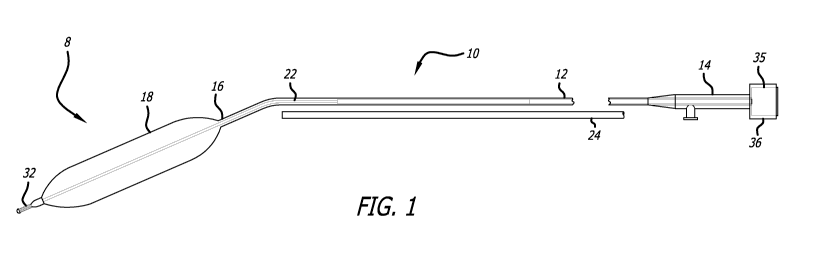
BRIEF DESCRIPTION OF THE DRAWINGS
[0021] FIG. 1 is a planar view of a system for dilating a stenosis in the
airway of a patient,
including a balloon catheter, a stylet, and an optional endoscope;
[0022] FIG. 2A is a planar view of a stylet having a bend in a distal portion
of the stylet;
[0023] FIG. 2B is a planar view of a stylet having a generally straight
configuration;
[0024] FIG. 3 is a partial perspective view of a grip disposed on an elongated
tubular
member of a balloon catheter that is holding an endoscope;
[0025] FIG. 4 is a cross-sectional view of a balloon catheter being introduced
into the airway
of a patient using a stylet with a bent region to bend the balloon catheter
during delivery;
[0026] FIG. 5 is the cross-sectional view of the balloon catheter from FIG. 4
positioned at a
stenotic region of the airway with the balloon inflated to dilate the stenotic
region;
[0027] FIG. 6A is a side view of an airway balloon catheter;
[0028] FIG. 6B is a magnified view of section AD from FIG. 6A;
[0029] FIG. 7A is a side view of an airway balloon catheter;
[0030] FIG. 7B is a magnified view of section AC from FIG. 7A;
[0031] FIG. 8A is a side view of a bump tubing used to form an outer member of
an airway
balloon catheter shaft;
[0032] FIGS. 8B and 8C are cross-sectional views of the bump tubing of FIG. 8A
at sections
C-C and F-F, respectively;
[0033] FIG. 9A is a side view of a bump tubing used to form an inner member of
an airway
balloon catheter shaft;
[0034] FIGS. 9B and 9C are cross-sectional views of the bump tubing of FIG. 8A
at sections
C-C and K-K, respectively;
[0035] FIGS. 1 OA and l0B are side views of a stylet with a proximal luer and
a distal portion
of the stylet, respectively; and
[0036] FIG. I OC is a side view of a core member of the stylet of FIGS. 1 OA
and 10B.
7
CA 02748535 2011-06-28
WO 2010/078148 PCT/US2009/069170
DETAILED DESCRIPTION
[0037] Before the present devices and methods are described, it is to be
understood that this
disclosure is not limited to particular embodiments described, as such may, of
course, vary. It is
also to be understood that the terminology used herein is for the purpose of
describing particular
embodiments only, and is not intended to be limiting.
[0038] Referring to FIG. 1, one embodiment is directed to a system 8 for
dilating a stenosis
in the airway of a patient. In this embodiment, the system 8 includes a
balloon catheter 10 and a
stylet 22. Optionally, the system may also include an endoscope 24, such as a
bronchoscope or
the like. As will be described further below, use of a balloon catheter 10 and
stylet 22 together,
each having dimensions, stiffness characteristics, and other features
specifically configured for
dilation of an airway, may help facilitate airway dilation procedures and
combat various
shortcomings of the prior art, such as difficulty advancing a dilator into a
constricted passage
and/or watermelon seeding of the balloon out of the stricture.
[0039] In the pictured embodiment, the balloon catheter includes a catheter
shaft 12 (or
"elongate tubular element") with a proximal section 14 and a distal section 16
and an inflatable
balloon 18 disposed on the distal section 16. The inflatable balloon 16 is in
communication with
an inflation lumen. A stylet 22 is also disposed within the catheter shaft 12.
In some
embodiments, at least a portion of the stylet 22 may have a greater stiffness
than at least a
portion of the catheter shaft 12, so that when the stylet 22 is bent and
inserted within the catheter
shaft 12, the catheter shaft 12 at least partially conforms to the shape of
the stylet 22. The stylet
22 is used to advance the balloon catheter 10 within an airway of a patient.
In this embodiment,
the system also includes an endoscope 24 disposed adjacent to the balloon
catheter 10 for
visualizing the placement of the balloon catheter 10 in the airway of the
patient. In use, the
balloon catheter 10 is inserted in the airway of the patient and the
inflatable balloon 18 is inflated
to dilate the stenosis in the airway of the patient.
[0040] With reference now to FIGS. 2A, 2B and 1 OA through l OC, the stylet 22
is described
in further detail. In general, and in most embodiments, the stylet 22 includes
a stiff proximal
portion providing stiffness to the catheter 10 and enabling the catheter 10 to
be advanced through
a patient's nostril or mouth and into position within a stenotic region of the
airway, and a flexible
distal portion, which may take a bend and which retains a bent shape when
disposed within the
8
CA 02748535 2011-06-28
WO 2010/078148 PCT/US2009/069170
balloon catheter 10. In one embodiment, the bend is pre-formed in the stylet.
In another
embodiment, the flexible portion is malleable, and the user can form the bend.
In another
embodiment, the bend may be pre-formed and it may also be malleable so the
user can change
the bend. In some embodiments, the stylet 22 is made of stainless steel, and
this material helps
the stylet 22 retain its bent shape even when disposed in the catheter 10.
This is a significant
advantage, since it allows a user to steer the catheter, using the bend.
[0041] Referring again to FIGS. 2A, 2B and 1 OA through l OC, in one
embodiment, the stylet
22 may include a core member 26 with a proximal section 28 and a distal
section 30, a coil 32
disposed around at least part of the distal section 30 of the core member 26,
and a luer lock
member 35 coupled with a proximal end of the core member 26 for coupling with
a hub on the
balloon catheter 10. In alternative embodiments, the stylet 22 may not include
a coil. In one
embodiment, the core member 26 and/or the coil 32 may be formed of nitinol. In
another
embodiment, the core member 26 and/or the coil 32 may be formed of stainless
steel or other
biocompatible material. In an embodiment in which stainless steel is used to
form at least the
core member 26, the stylet 22 may be advantageously more able to maintain a
bent shape when
disposed with the balloon catheter 10. The distal portion 30 of the stylet may
include a bend or
curve 34 that is stiff enough to bend the balloon catheter 10 during the
placement of the balloon
catheter 10 within the airway of the patient. In another embodiment, the
stylet 22 may be
provided in a generally straight configuration, as in FIG. 2B. In some
embodiments, the stylet 22
may be pre-formed to have a bend 34. In some embodiments, the stylet 22 may
alternatively or
additionally be malleable, such that a user may bend the stylet 22 and the
stylet 22 maintains the
user-created bend. In one embodiment, a proximal section 28 of the stylet 22
may be generally
stiff, a distal section 30 may be generally malleable, and an extreme distal
portion may be
atraumatic and very flexible or even floppy. In some embodiments, this
variation in flexibility
along the length of the stylet 22 may be achieved by using different
materials, such as stainless
steel and nitinol. In another embodiment, one material such as stainless steel
may be used and
the diameter of the stylet 22 may be altered to achieve the variation in
flexibility along the length
of the stylet 22.
[0042] According to various embodiments, the stylet 22, core member 26 and
coil 32 may
have any number of configurations and combinations of dimensions. As shown in
FIG. I OC, for
example, in one embodiment, core member 26 may include a proximal portion 28
and a distal
9
CA 02748535 2011-06-28
WO 2010/078148 PCT/US2009/069170
portion 30 having multiple portions 30a, 30b, 30c, 30d having differing
diameters. In various
embodiments, any of a number of different diameters, lengths, and the like may
be used in
forming core member 26. In the embodiment shown, for example, the diameter of
the proximal
portion is about 0.8 mm the diameter of the first distal portion 30a tapers
from about 0.8 mm to
about 0.4 mm, the diameter of the second distal portion 30b is about 0.4 mm,
the diameter of the
third distal portion 30c tapers from about 0.4 mm to about 0.13 mm, and the
diameter of the
fourth, distal-most distal portion 30d is about 0.13 mm. In one embodiment,
the length of the
first distal portion 30a is about 6-8 cm, the length of the second distal
portion 30b is about 2-4
cm, the length of the third distal portion 30c is about 4-5 cm, and the length
of the fourth distal
portion is about 3-5 cm. In one embodiment, the core member 26 may be ground
down to form
the various distal portions 30a-d. For example, in one embodiment, the distal-
most fourth distal
portion 30d may be ground to a flat configuration having a height of about
0.06 mm, a width of
about 0.13 mm, and a length of about 2.5-4.0 cm and preferably about 3.0-3.5
cm. Of course,
this is merely one exemplary embodiment, and in alternative embodiments many
different
dimensions and combinations may be used. Generally, it may be advantageous to
provide a core
member 26 that tapers over its length so that it can retain a bent
configuration along a portion of
its length while disposed in a balloon catheter 10 while at the same time
providing sufficient
proximal stiffness to facilitate pushing the coupled stylet 22 and catheter 10
and also having a
flexible, atraumatic distal tip.
[0043] Referring to FIGS. l0A and 10B, the coil 34 of the stylet 22 may have
any suitable
overall length and any of a number of different coil spacings (or "pitches").
For example, where
a more flexible distal end of the stylet 22 is desired, a larger pitch (more
spacing between coils)
may be used. Where a stiffer distal end is desired, a smaller pitch may be
used. In one
embodiment, for example, the coil 34 may have a pitch of between about 0.13 mm
and about
0.25 mm and more preferably about 0.20 mm. The coil 34 may be disposed over
any suitable
length of the core member 26. At the extremes, the coil 34 may be disposed
over the entire
length of the core member 26, or the coil 34 ma be eliminated from the stylet
22 altogether. In
various other embodiments, the coil 34 may be disposed over a length of the
core member 26
between about 5 cm and about 25 cm, and more preferably between about 10 cm
and about 15
cm. In some embodiments, the coil 32 may be soldered at its proximal and
distal ends to the
core member 26. In some embodiments, the solder at the distal end may form a
solder tip 33. In
CA 02748535 2011-06-28
WO 2010/078148 PCT/US2009/069170
other embodiments, a separate distal tip member may be added to the stylet 22
via adhesive or
other attachment means.
[0044] In various embodiments, the stylet 22 may have an overall length
approximately as
long or slightly longer than the catheter shaft 12 of the balloon catheter 10.
In some
embodiments, for example, the stylet 22 may include an atraumatic, flexible
distal tip portion
that extends distally out of the catheter shaft 12 when the stylet 22 is fully
disposed within the
catheter 10. This tip portion may be, for example, about 0.25 cm to about 8 cm
or more
preferably about 1-5 cm in length and may facilitate the ability of a user to
advance the system 8
through a patient's airway atraumatically. In some embodiments, the overall
length of the stylet
may vary from about 30 cm to about 80 cm, and more preferably from about 45 cm
to about 60
cm. Of the overall length, a flexible distal portion of the sylet 22 may be
from about 5-20 cm,
and preferably from about 10-15 cm, in some embodiments. The stylet 22 may
include a bend
34 having any suitable angle, such as from greater than 0 degrees to about 20
degrees. In one
embodiment, the largest diameter of stylet 22 may be about 1.3 mm, and
preferably 0.9 mm or
less, and the diameter may decrease distally to about 0.13 mm +/- 0.013 mm.
[0045] In some embodiments, either where the stylet 22 includes a preformed
bend 34 or
where it is provided in a straight configuration, the stylet 22 may be
malleable so that a user can
form the bend 34 or change the angle of the bend 34. This malleability allows
a user to adjust a
bend angle according to the airway anatomy of a particular patient. In most
embodiments, the
stylet 22 retains the bend 34, or approximately the same bend 34 although it
may straighten
somewhat, when the bent stylet is placed in the balloon catheter 10. In some
embodiments, the
bend 34 may be maintained during and sometimes after the balloon catheter 10
is positioned in
the airway of a patient. In other embodiments, the stylet 22 may have a
stiffness such that the
bend 34 partially or completely straightens out in the narrow airway of the
patient. As shown in
FIG. 2B, one embodiment of the stylet 22 includes three sections, a flexible
section 40 near the
distal end that can range from about 0.25 cm to about 8 cm or more preferably
about 1-5 cm in
length. In one embodiment, the flexible section 40 is atraumatic and may or
may not include the
coil 32. A central section 42 of the stylet may be malleable for introducing a
curve or bend to
the stylet 22 to help advance and place the balloon catheter 10 within the
airway of the patient.
The central section 42 may be about 0.5 cm to about 10.0 cm in length in one
embodiment. In
one embodiment, the malleable central section 42 takes a preformed shape in
free space, such as
11
CA 02748535 2011-06-28
WO 2010/078148 PCT/US2009/069170
a bend or curve, and then conforms to the shape of the patient's airway. A
stiff section 44 is near
the proximal end of the stylet 22 and can have a length of about 10 cm to
about 35 cm in one
embodiment. In one embodiment, any of these three sections 40, 42 or 44 may be
bonded to one
another. In another embodiment, core member 26 may be ground down in sections
to give those
sections smaller diameters.
[0046] The stylet 22 in one embodiment may have a greater stiffness along a
portion of its
length where the bend 34 is located or may be formed than the corresponding
portion of the
balloon catheter 10 that resides over the bend 34. In this embodiment, the
catheter shaft 12
conforms to the shape of the stylet 22 (bent or straight) during placement
within the stenotic
region.
[0047] In one embodiment of the system 8, the stylet 22 may be attached to the
balloon
catheter 10, and in another embodiment, the stylet may be removably connected
to the balloon
catheter 10. In some embodiments, the stylet 22 may include a luer lock member
35 with threads
on the proximal section 28 that screw into opposing threads disposed on a luer
36 of the balloon
catheter 10. In another embodiment, the balloon catheter 10 may include a
locking mechanism
(not shown) to lock the stylet 22 in position within the catheter shaft 12.
The locking mechanism
can be any mechanical device, include a lever, a ball and pin, and luer. In
one embodiment,
when the stylet 22 is connected to the balloon catheter 10, the all or part of
the distal section 30
of the stylet 22 may extend out of the distal end of the catheter shaft 12.
Still in other
embodiments, the stylet 22 may be locked to the balloon catheter 10 at
different positions or
lengths so the distal end of the stylet 22 extends out of or is positioned
within the balloon
catheter 10 at different lengths. The length, diameter(s) and stiffness
characteristics of the stylet
22 may be varied in different embodiments to confer different performance
characteristics to the
overall system 8.
[0048] Use of the stylet 22 while inserting the balloon catheter 10 helps to
guide the distal
end of the balloon catheter 10 through the airway of the patient and to the
stenotic region. The
stylet provides increased steerability during advancement of the balloon
catheter 10.
Torquability of the balloon catheter 10 is also increased when using the
stylet 22. In some
embodiments, the luer lock member 35 of the stylet 22 and the luer 36 of the
balloon catheter 10
12
CA 02748535 2011-06-28
WO 2010/078148 PCT/US2009/069170
mate together, so that the stylet 22 and balloon catheter 10 may be rotated
together and thus
steered into a constricted portion of an airway.
[0049] In one embodiment, the stylet 22 may have a light emitting portion,
such as a light
emitting distal end or tip. In one such embodiment, for example, the stylet 22
may include one
or more light fibers to tranmit light from a light source attached to the
proximal end of the stylet
22 to its distal end. Light from a light emitting stylet 22 may be used to
help a user visualize a
patient's airway from the inside using a scope and/or in some cases from the
outside via
transillumination through the patient's skin. One embodiment of a light
emitting guidewire
device that may be used or modified to achieve such an illuminating stylet 22
is the Relieva
LumaTM Sinus Illumination Guidewire/System, manufactured by Acclarent, Inc. of
Menlo Park,
CA. Such an illuminating stylet 22 may have any of the features described
above with the
additional feature of light emitting capability.
[0050] With reference now to FIGS. 6A and 6B, in one embodiment, a balloon
catheter 50
may include a catheter shaft 52 having an outer shaft member 54 and an inner
shaft member 56,
an inflatable balloon 58 attached to the shaft 52 at a proximal attachment
point 62 and a distal
attachment point 64, and a hub 60 having a stylet port 66 and an inflation
port 68. In this
embodiment, the outer shaft member 54 is disposed over a portion of the inner
shaft member 56,
with the latter continuing to the distal end of the catheter 50. The balloon
58 is attached at the
proximal attachment point 62 to the outer member 54 and at the distal
attachment point 64 to the
inner shaft member 56, either via adhesive or other attachment means. Thus, an
inflation lumen
(too small to view on FIG. 6A) is formed between the inner and outer shaft
members 56, 54, with
inflation fluid passing into the catheter 50 from an inflation device (not
shown), through the
inflation port 68, into the inflation lumen, and into the balloon 58. The
stylet 22, which is not
pictured in FIGS. 6A and 6B, generally resides within an inner lumen of the
inner shaft member
56, and may extend distally out of the distal end of the catheter 50 and
couple proximally with
the hub 60.
[0051] In various embodiments, the balloon catheter 50 and its various
components may
have any number of suitable sizes, shapes and configurations. For example, the
balloon 58 may
have different lengths and diameters in different embodiments, to accommodate
different patient
anatomies. The overall catheter length and diameter may also vary. Thus, the
following
13
CA 02748535 2011-06-28
WO 2010/078148 PCT/US2009/069170
description of embodiments is exemplary only and not limiting of the invention
which is defined
by the granted claim(s) and equivalents thereof. In some embodiments, for
example, the overall
length of the balloon catheter 50 (i.e., from the proximal end of the hub 60
to the distal end of the
catheter shaft 52) is about 35-70 cm, more preferably less than or equal to
about 50 cm, and more
preferably about 45 cm 5 cm. Limiting the overall length of the catheter 50
to these ranges
makes the catheter easier to handle and manipulate with one hand, especially
compared to the
currently available vascular catheters, which are much longer and floppier
than the present
catheter 50 and thus more challenging to use for an airway dilation procedure.
[0052] The working length of the balloon 58 in FIGS. 6A and 6B is about 40 mm
2 mm.
By "working length" it is meant the length between the two tapered portions of
the balloon 58.
In alternative embodiments, the working length of the balloon 58 may range
from between about
mm and about 60 mm and more preferably about 16-45 mm. In one embodiment, a
variety of
lengths may be provided, including about 16 mm, 24 mm and 40 mm. The outer
diameter of the
fully inflated working length of the balloon 58 may also vary. In the
embodiment shown in
FIGS. 6A and 6B, the balloon 58 has an inflated diameter of about 14.1 mm
0.5 mm. In some
embodiments, the balloon diameter may range from about 3 mm to about 24 mm and
more
preferably about 5-15 mm. In one embodiment, a variety of diameters may be
provided,
including about 5 mm, about 7 mm, about 10 mm, about 14 mm, about 20 mm and
about 24 mm.
For example, a combination of balloon sizes and lengths may be provided, such
that a physician
may choose an appropriate size for an adult or pediatric patient. In one
example, the following
combinations may be provided (first dimension is diameter, second is length):
5 mm x 24 mm; 7
mm x 24 mm; 10 mm x 40 mm; and 14 mm x 40 mm. Of course, any of a number of
other
combinations of sizes of balloons 58 may be provided.
[0053] In various embodiments, any suitable material may be used to form the
balloon 58.
The balloon 58 may be compliant, semi-compliant or non-compliant, according to
various
embodiments, although in a preferred embodiment the balloon 58 is either semi-
compliant or
non-compliant. The balloon 58 may be made of nylon or other polymer or the
like, such as in
one example PTFE. In some embodiments, the balloon 58 may include an outer
slip-resistant
surface, which may be formed by a textured surface or a coating. Such a
surface may help
prevent watermelon seeding of the balloon 58 out of an airway stricture during
inflation and/or
14
CA 02748535 2011-06-28
WO 2010/078148 PCT/US2009/069170
may facilitate re-wrapping the balloon 58 by hand after deflation, for example
if the balloon 58 is
to be used for a second or subsequent dilation procedure.
[0054] In some embodiments, the inflatable balloon 58 may inflate
preferentially. For
example, the inflatable balloon 58 can be designed to inflate in a dumbbell
shape. Typically, this
shape can be created by making the proximal and distal ends of the balloon 58
with a different
balloon wall thickness than the wall thickness of the central portion of the
balloon 58. In other
embodiments, a sleeve may be placed around the central portion of the balloon
58 to prevent the
central section from inflating at the same rate as the proximal and distal
ends of the balloon 58.
Also, the central section of the balloon 58 may be heat treated to prevent it
from inflating at the
same rate as the ends of the balloon 58. Still in other embodiments, sections
of the balloon 58
may inflate at different rates depending on the location of the inflation
ports.
[0055] According to various embodiments, the catheter shaft 52 (outer shaft
member 54 and
inner shaft member 56) may be formed of any suitable material. In some
embodiments, it may
be advantageous to form the shaft 52 from material(s) selected so that the
shaft 52 is unlikely to
kink when bent, such as when bent by the stylet 22 and/or a user. One such
material, for
example, is Pebax, although other polymers may be used in alternative
embodiments.
[0056] The outer shaft member 54, the inner shaft member 56, or both may also
have any
suitable color and may include one or more shaft markings. The shaft color and
markings may
be built into the shaft 52 by using a colored material or may be added by
applying paint or
another colorant. In one embodiment, the shaft 54 may have a dark color, such
as black or dark
blue, and one or more light colored markings may be applied over the dark
shaft 54. In various
embodiments, the markings (not shown in the figures) may include direct
visualization markings
(viewed directly with the naked eye or an endoscope), radiographic markings
(viewed with a
radiographic device such as intraoperative fluoroscopy), or both. For example,
in one
embodiment, two radiographic markings may be positioned in the inner shaft
member 56 at the
locations of the two working ends of the balloon 58, and two direct
visualization markings may
be positioned on the outer shaft 54 approximately 1 cm and 2 cm proximal to
the proximal
attachment point. Optionally, additional direct visualization markings may be
included. The
direct visualization markings may be viewed with a bronchoscope or other
endoscope to help a
physician approximate the location of the balloon 58 relative to anatomy,
while the radiographic
CA 02748535 2011-06-28
WO 2010/078148 PCT/US2009/069170
markings may be viewed with a fluoroscopy device to see where the working ends
of the balloon
58 are located relative to an airway constriction. In various embodiments, any
suitable
combination, size and color of markings may be used. One example of shaft
color and shaft
markings, which could be used or modified for the balloon catheter 50, is the
Relieva Solo ProTM
Sinus Balloon Catheter, manufactured by Acclarent, Inc. of Menlo Park, CA.
[0057] Referring now to FIGS. 8A-8C, in one embodiment the outer shaft member
54 of the
catheter shaft 52 may include a distal portion 70 (FIG. 8C) having a first
diameter and a proximal
portion 72 (FIG. 8B) having a second, larger diameter. In one embodiment, this
difference in
diameter may be achieved by using "bump tubing," which has a larger wall
thickness proximally
than distally. Alternatively, the difference could be built into the outer
shaft member 54 by an
extrusion or other technique. In one embodiment, for example, the outer
diameter of the
proximal portion 72 may be about 2.1 mm, and the outer diameter of the distal
portion 70 may be
about 1.8 mm, with the inner diameter of both being about 1.6 mm. In some
embodiments, the
maximum outer diameter of the outer shaft member 54 immediately proximal to
its attachment to
the balloon 58 may be about 1.5-2.5 mm and in one embodiment about 2 mm (or
about 1.8 mm).
Limiting the outer diameter of outer shaft 54 near the balloon 58 within this
range enables or at
least enhances the ability of a user to view the balloon 58 using an endoscope
in the airway. A
larger outer shaft diameter makes such visualization difficult or impossible,
because there is not
sufficient room in the airway to fit the catheter shaft 52 and the endoscope
24. The inner
diameter of outer member may be about 1.3 mm-1.8 mm, more preferably about 1.5
mm-1.65
mm, and in one embodiment about 1.6 mm-1.62 mm.
[0058] Referring now to FIGS. 9A-9C, the inner shaft member 56 of the catheter
shaft 52
may also include a distal portion 74 (FIG. 9C) having a first diameter and a
proximal portion 76
(FIG. 9B) having a second, larger diameter. In one embodiment, for example,
the proximal
portion 76 may have an outer diameter of about 1.5 mm 0.025 mm, and the
distal portion 74
may have an outer diameter of about 1.2 mm 0.025 mm. In some embodiments,
the inner and
outer diameters of the inner shaft member 56 may be no more than about 1.3 mm
and 1.8 mm
respectivly, more preferably no more than and 1.02 mm and 1.3 mm respectively,
and in one
embodiment no more than about 0.97 mm and 1.22 mm respectively. Again, bump
tubing may
be used in one embodiment.
16
CA 02748535 2011-06-28
WO 2010/078148 PCT/US2009/069170
[0059] Referring again to FIGS. 6A and 6B, in some embodiments, the inner
shaft member
56 may extend distally beyond the distal end of the balloon 58 by about 1 mm
to about 10 mm,
more preferably by about 5 mm 1 mm. This distal end of the inner shaft
member 56 may act as
an atraumatic tip, along with a protruding distal end of the stylet 22, which
may extend further
out of the inner shaft member. In some embodiments, where a larger diameter
balloon is used
(10 mm or more, for example), a small segment of the inner shaft member 56
toward its distal
end may have a larger outer diameter, so that the larger diameter balloon may
be adequately
bonded to the inner shaft member 56 at the distal attachment point 64. This
serves the purpose
of keeping the inner shaft member 56 small along the rest of its length (i.e.,
lower profile means
it is easier to advance through the airway), while still allowing the larger
balloon to be bonded to
it. In one embodiment, the larger outer diameter may be performed by adding
material to the
inner shaft member 56 at the distal attachment point 64 before bonding. In
another embodiment,
bump tubing may be used, with the inner shaft member 56 constructed with the
larger diameter
built-in at the distal attachment point 64.
[0060] The inner and outer diameters of the inner shaft member 56 and outer
shaft member
54 may confer several advantages to the balloon catheter 50. For example,
moving from a larger
diameter proximally to a smaller diameter distally while keeping the inner
diameter of the shaft
52 as large as possible, helps minimize deflation time of the balloon 58 after
an inflation. This
allows for quick removal and/or adjustment of the balloon 58 after a dilation.
This quick
deflation can be achieved while also providing a relatively small diameter
catheter shaft 52
toward the balloon 58 and the distal end of the catheter 50. This facilitates
both advancement of
the catheter 50 into a desired treatment position in the airway as well as
viewing the proximal
end of the balloon 58 with a bronchoscope positioned in the airway. The small
profile catheter
shaft 52, combined with a balloon 58 having a sufficiently large diameter to
dilate an airway
constriction, allows a physician to treat both pediatric and adult patients
who have very different
anatomies.
[0061] Referring now to FIGS. 7A and 7B, another embodiment of a balloon
catheter 80 may
include a catheter shaft 82 having an inner shaft member 86 and an outer shaft
member 84, a
balloon 88 coupled with the shaft 82 at or near its distal end, and a hub 90
coupled with the shaft
82 at or near its proximal end. This embodiment of the balloon catheter 80 is
similar to the
balloon catheter 50 of FIGS. 6A and 6B but has a differently sized balloon 88.
In this
17
CA 02748535 2011-06-28
WO 2010/078148 PCT/US2009/069170
embodiment, the balloon 88 is about 22-26 mm long and about 4.5-5.5 mm in
diameter when
fully inflated. As mentioned previously, in various embodiments any of a
number of differently
sized balloons may be provided. Physicians may be provided with the choice of
balloon sizes to
address pediatric patients or adult patients having differently sized airways.
In embodiments
such as that shown in FIGS. 7A and 7B, with a smaller diameter balloon 88 than
the earlier
describe balloon catheter 50, the inner shaft member 86 may not increase in
diameter at the
location of the distal attachment point (FIG. 7B). The increased diameter
described earlier to
accommodate a larger diameter balloon 58 may not be necessary with a smaller
diameter balloon
88. Generally, any features described above may be included in this embodiment
of the balloon
catheter 80.
[0062] In some embodiments, the distal end of the catheter shaft 84 may be
sealed to prevent
the stylet 22 from extending out of the distal end. The balloon catheter 80 is
compatible with a
bronchoscope 24, endoscope or other scope device for direct visualization of
the stenotic region.
Further, the balloon catheter 80 can be integrated with an illuminating
guidewire (for example,
the Relieva LumaTM Sinus Illumination Guidewire from Acclarent, Inc.). The
illuminating
guidewire device is connected to a light source and includes an illuminating
portion at a distal
end that illuminates. Illumination of the illuminating guidewire device can
provide additional
light in the airway of the patient to visualize the placement of the balloon
catheter at the stenotic
region.
[0063] Referring to FIG. 3, in one embodiment, an airway dilation balloon
catheter system
100 may incude a balloon catheter 110, a stylet 120, a scope 124, and a
coupling member 138 for
coupling the scope 124 to the balloon catheter 110. The balloon catheter 110
may include a shaft
114 and a luer 136, which locks with a luer lock member 134 of the stylet 120.
In one
embodiment, the coupling member 138 may allow the scope 124 to be removably
coupled with
the catheter 110. In one embodiment, the scope 124 may be frictionally fit
into the coupling
member 138. In some embodiments, the coupling member 138 may comprise a
handle. As
shown in FIG. 3, the scope 124 may be secured into the coupling member 138 on
either side of
the balloon catheter 110. Securing the scope 124 to the balloon catheter 110
helps to prevent
slippage during dilation of the inflatable balloon. Also, securing the scope
124 to the balloon
catheter 110 allows the physician to hold both devices in a single hand. In
another embodiment,
the coupling member 138 can be attached to the luer 136 of the balloon
catheter 110.
18
CA 02748535 2011-06-28
WO 2010/078148 PCT/US2009/069170
[0064] With reference now to FIGS. 4 and 5, a method for dilating an stenotic
region 246 in
an airway A, such as in a case of subglottic stenosis, is shown. In one
embodiment, the method
includes introducing an airway dilation system 210 through the mouth and into
the airway of the
patient. As described in detail above, the airway dilation system 210 may
include a balloon
catheter 212 with an inflatable balloon 218, disposed over a stylet 222, with
a distal tip 232 of
the stylet 222 protruding from the catheter 212 and acting as an atraumatic
tip. Optionally, in
some embodiments the system may include a bronchoscope (not shown) or other
scope device.
In some embodiments, the method may involve bending the airway dilation system
210, either
by the user or by the manufacturer of the system 210. In some cases, the
stylet 222 may be bent
and then inserted into the balloon catheter 212, while in other cases the
stylet 222 and balloon
catheter 212 may be bent together, with the stylet 222 already residing in the
catheter 212. Thus,
in some cases, the stylet 222 may be malleable while in others it may not. The
support of the
stylet 222 and the bend in the overall system 210 may help a physician
navigate the system 210
through the patient's airway to position the balloon 218 within at least a
portion of the stenotic
region 246. As shown in FIG. 4, the inflatable balloon 218 of the catheter 212
is in an
unexpanded configuration during advancement and placement of the balloon
catheter 212.
[0065] As shown in FIG. 5, once the balloon 218 is positioned within the
stenotic region 246
of the airway A, the inflatable balloon 218 is inflated to dilate the stenotic
region 246. In some
embodiments, the stylet may be formed such that the bent or curved region of
the stylet
straightens out once the balloon catheter is positioned with the narrow airway
A of the patient.
In other embodiments, as in FIG. 5, the bend in the system 210 may be retained
even when
positioned in the airway A.
[0066] In one embodiment, the stylet distal tip 232 may include an
illumination capability.
In such an embodiment, the method may further include illuminating the stylet
distal tip 232 and
viewing the illumination from inside the airway (using a scope) and/or from
outside the patient
via transillumination.
[0067] In some embodiments, the stylet 222 remains in the balloon catheter 212
during
inflation of the balloon 218. Maintaining the stylet 222 in the catheter 212
during inflation may
give the catheter 212 added column strength and help maintain the position of
the balloon 218
within the stenotic region 246, thus avoiding watermelon seeding. In an
alternative embodiment,
19
CA 02748535 2011-06-28
WO 2010/078148 PCT/US2009/069170
the method may include removing the stylet 222 from the balloon catheter 212
before inflating.
The stylet 222 may be removed from the balloon catheter 212, for example,
after the balloon
catheter 212 is properly positioned within the airway A of the patient. In
another embodiment,
the stylet 222 can be removed after the stenosis has been dilated but before
removing the balloon
catheter 212 from the patient.
[0068] The method may also include advancing an endoscope or bronchoscope (not
shown)
along the airway A of the patient and positioning a distal end of the
endoscope near the stenotic
region 246 to visualize placement of the airway dilation system 210. The
endoscope may be
attached to the balloon catheter 212 using the coupling member 138 in one
embodiment, to help
prevent movement and slippage during balloon dilation. After the dilation is
performed, the
endoscope can detached from the grip and removed from the patient.
Alternatively, the
endoscope may be separate from the catheter 212. In alternative embodiments,
the endoscope
may be positioned alongside the balloon catheter 212 or the endoscope may be
positioned within
or through the balloon catheter 212. In another embodiment, the method of
dilating the
subglottic stenosis includes inserting a bronchoscope into the airway A of the
patient and then
passing the balloon catheter 212 through the bronchoscope.
[0069] In one embodiment, the method may include inflating the inflatable
balloon 218 more
than once to dilate the stenotic region 246 of the airway A. FIG. 5 shows the
inflatable balloon
in an expanded configuration to dilate the stenotic region. The physician will
inflate the
inflatable balloon 218 to a desired pressure during each dilation of the
stenosis. Proper dilation
of the stenotic region can 246 be confirmed by visualizing the region with the
bronchoscope/endoscope.
[0070] The airway dilation system 210 and method described above increase the
ease of use
for the physician performing the dilation of the stenotic region 246 in the
airway A of the patient.
In some embodiments, the physician can manipulate the system 210 using one
hand, thus leaving
the other hand free to hold a bronchoscope or other device. The combination of
the balloon
catheter 212, with its advantageous length, shaft and balloon diameters and
overall configuration,
and the stylet 222, with its bend to facilitate airway navigation, will likely
make an airway
dilation procedure easier and more often successful. Further, the atraumatic
design of the
balloon catheter 212 and stylet 222 helps prevent damage to the airway A and
vocal cords of the
CA 02748535 2011-06-28
WO 2010/078148 PCT/US2009/069170
patient during delivery and removal. Also, the design helps prevent movement
and slippage of
the balloon catheter 212 during dilation of the stenotic region 246, which
translates into a more
controlled dilation.
[0071] The methods and devices described herein make reference to certain
examples and
embodiments, but various additions, deletions, alterations and modifications
may be made to
these examples and embodiments and or equivalents may be substituted without
departing from
the intended spirit and scope of what is disclosed. For example, any element
or attribute of one
embodiment or example may be incorporated into or used with another embodiment
or example,
unless to do so would render the embodiment or example unsuitable for its
intended use. In
addition, many modifications may be made to adapt a particular situation,
material, composition
of matter, process, process step or steps, to the objective, spirit and scope
of the present
disclosure. All such modifications are intended to be within the scope of the
claims appended
hereto.
21