Language selection

Search

Patent 2748609 Summary

Third-party information liability

Some of the information on this Web page has been provided by external sources. The Government of Canada is not responsible for the accuracy, reliability or currency of the information supplied by external sources. Users wishing to rely upon this information should consult directly with the source of the information. Content provided by external sources is not subject to official languages, privacy and accessibility requirements.

Claims and Abstract availability

Any discrepancies in the text and image of the Claims and Abstract are due to differing posting times. Text of the Claims and Abstract are posted:

  • At the time the application is open to public inspection;
  • At the time of issue of the patent (grant).
(12) Patent: (11) CA 2748609
(54) English Title: FRACTURING TOOL ANCHOR
(54) French Title: ANCRAGE POUR OUTIL DE FRACTURATION
Status: Granted
Bibliographic Data
Abstracts

English Abstract

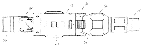
The present invention is directed to a fracturing tool anchor adapted for use with a work string in a wellbore. In a preferred embodiment, the anchor has a housing with a central passage and an uphole and downhole end. The housing has a plurality of ports positioned circumferentially around the housing and along the length of the housing. The ports each contain an engagement member, such as a piston, and a return spring. The engagement member is adapted to extend radially outward when the anchor is pressure activated, to engage the wall of the casing or wellbore. The present application is also directed to a fracturing tool anchor that does not need to be pressure activated and utilizes slips as the engagement members.


French Abstract

La présente invention porte sur un ancrage pour outil de fracturation adapté pour une utilisation avec un train de tiges de travail dans un trou de forage. Dans un mode de réalisation préféré, lancrage comprend un logement comportant un passage central et une extrémité de trou de surface et de trou de fond. Le logement comporte une pluralité dorifices positionnés de manière circonférentielle autour du logement et le long de la longueur du logement. Les orifices comportent chacun un élément dengagement, comme un piston, et un ressort de rappel. Lélément dengagement est adapté pour se prolonger radialement vers lextérieur lorsque lancrage est activé par la pression, pour engager la paroi du tubage de puits ou du trou de forage. La présente demande porte également sur un ancrage pour outil de fracturation qui ne nécessite pas une activation par la pression et emploie des manchons comme éléments dengagement.

Claims

Note: Claims are shown in the official language in which they were submitted.


Claims:

1. A fracturing tool anchor adapted for use in a wellbore, the fracturing
tool anchor
comprising:
a housing having an uphole end, a downhole end and a central passage between
the
uphole end and the downhole end;
a plurality of ports spaced circumferentially around the housing and/or spaced

longitudinally along the length of the housing between the uphole end and the
downhole end; and
a plurality of pistons positioned within the plurality of ports and in fluid
communication
with the central passage, the plurality of pistons, upon application of
pressure
through the central passage, extending radially outwards through the plurality
of
ports to engage a wall of the wellbore or casing;
wherein each port is counterbored having a large diameter bore facing the
wellbore and a
small diameter bore adjacent the large diameter bore, and each of the
plurality of pistons has a
large diameter portion fit to the large diameter bore and a small diameter
portion fit to the small
diameter bore.
2. The fracturing tool anchor according to claim 1, wherein an outward face
of each of the
plurality of pistons is serrated to firmly engage the wall of the wellbore or
casing.
3. The fracturing tool anchor according to any one of claims 1 to 2,
wherein the fracturing
tool anchor further comprises a spring retainer for returning the plurality of
pistons to a rest
position.
4. The fracturing tool anchor according to any one of claims 1 to 3,
wherein the uphole end
and the downhole end of the housing are configured to attach a work string and
other downhole
tools, respectively.
5. The fracturing tool anchor according to any one of claims 1 to 3,
wherein the uphole end
is adapted to connect to a work string and the downhole end is adapted to
connect to downhole
tools or other apparatuses.

4


6. The fracturing tool anchor according to any one of claims 1 to 5,
wherein an annular
shoulder is formed between the port's large and smaller diameter bores, a
plurality of recesses
being provided in the housing about the annular shoulder.
7. The fracturing tool anchor of claim 3 wherein the spring retainer
extends longitudinally
from the housing and across each of the plurality of pistons.
8. The fracturing tool anchor of claim 7 wherein an outward facing surface
of each of the
plurality of pistons is fit with a longitudinal slot aligned with the spring
retainer.
9. The fracturing tool anchor of claim 7 wherein a return spring is fit
between the spring
retainer and each of the plurality of pistons.
10. The fracturing tool anchor of claim 9 wherein the return spring is fit
into a pocket in the
piston.


Description

Note: Descriptions are shown in the official language in which they were submitted.


CA 02748609 2011-08-08
Fracturing Tool Anchor

Field of the Invention

The present invention relates generally to a downhole tool for use in oil
field applications.
In particular, this invention relates to an anchor for use with a work string,
such as coiled
tubing, in a wellbore, such as a horizontal wellbore.

Background of the Invention

In recent years there has been a large increase in the number of wells that
have been drilled
with horizontal portions. When servicing or completing these kinds of wells it
is common to
use coiled tubing to convey the tools or instruments to the portion of the
wellbore of interest,
owing to its flexibility and speed of deployment compared to other methods.
Compared to
traditional drill pipe, coiled tubing is quite thin walled, and subject to
buckling if a large
compressive force is applied to it.

If the bottom sealing elements on a selective frac packer fail, a net upward
force is generated
due to the pressure contained between the upper sealing device(s) and the toe
of the well.
This upward force can result in the coiled tubing buckling under the
compressive loading.
The upward force can be mitigated in wells comprised of 4.5" casing or
smaller, however in
wells with 5.5" casing or larger the hydraulic forces can easily exceed
200,000 lbs. In order
to prevent buckling of the coiled tubing, it is necessary to provide a device
that can transmit
the upward compressive force in the event of a seal failure away from the
coiled tubing and
to the casing and thereby to the earth, rather than allowing the coiled tubing
to be subjected
to the compressive force.

Summary of the Invention

In a first aspect of the present invention there is provided a fracturing tool
anchor
adapted for use in a wellbore, the fracturing tool anchor comprising:

an housing having an uphole and a downhole end;

the housing having a central passage between the uphole and downhole end;

a plurality of engagement members positioned between the uphole and downhole
end;

the engagement members adapted to extend radially outwards to engage a casing
or
wellbore wall;

wherein, upon setting, the engagement members extend radially outwards to
engage
the casing or wellbore wall.

In a preferred embodiment of the present invention, the engagement members are
pistons located in ports, positioned circumferentially around the housing and
along the
length of the housing. The anchor is pressure activated in order to engage the
wall of the
casing or wellbore.

1


CA 02748609 2011-08-08

In another aspect of the present invention, there is provided a fracturing
tool anchor that
does not need to be pressure activated and utilizes slips as the engagement
members.
Brief Description of the Drawings

The embodiments of the present invention are described below with reference to
the
accompanying drawings in which:

Fig. 1 is a perspective view of an anchor embodying the invention;
Fig. 2 is a cross-section of an anchor embodying the invention; and
Fig. 3 is a view of another embodiment of the invention.

Description of the Invention

As shown in Figures 1 and 2, a fracturing tool anchor 15 consists of a housing
10, which is
preferably cylindrical in shape. The housing 10 has an uphole and downhole
end.
Positioned on the ends are threads 12 for attaching the anchor 15 to a work
string, which
may be coiled tubing, jointed pipe. The threads 12 may also be used for
attaching other tools
to the anchor 15. In the illustrated embodiment, the threads are 2.750-10 Stub
Acme threads.
In the embodiment illustrated in Figures 1 and 2, the fracturing tool anchor
15 has a plurality
of ports 14 positioned circumferentially around the housing 10. The ports 14,
in the
illustrated embodiment, are also spaced longitudinally along the housing 10
between the
downhole and uphole ends. Within each port 14 is an engagement member, which
is
preferably a piston 2. Also located in each port 14 is a return spring 5. The
piston port is
angled toward the uphole direction of the anchor 15 to provide stronger
engagement
between the piston face and the wellbore or casing when an upward force is
applied to the
anchor 15.

Covering the piston 2 to ensure that its range of travel does not exceed the
bore in the
housing is a spring retainer 3. Spring retainer 3 is secured to the housing 10
with a pair of
cap screws 4. Piston 2 is sealingly engaged with the bore machined in housing
10 by 0 rings
6 and 7. In the illustrated embodiment, the 0 rings 6 and 7 are highly-
saturated nitrile 80
durometer O-rings.

The outward facing surface of piston 2 is serrated to firmly engage the wall
of the wellbore,
or casing, and prevent relative movement between the anchor 15 and the earth.
In this
manner, any upward forces originating from downhole of the anchor 15 can be
transmitted
to the earth, rather than to the work string uphole of the anchor 15, thus
ensuring no
excessive loads are imposed upon the work string.

When the work string is positioned in the hole at the desired location, the
anchor 15 is set by
applying pressure to the central passage 20 of the anchor 15 and the pistons 2
are biased
radially outward, wherein the serrated faces engage the casing or wellbore
wall. When it is
desired to remove the work string from the hole, the pressure is reduced in
the central
passage 20, and the springs 5 return the pistons 2 to their rest position and
the anchor can be

2


CA 02748609 2011-08-08

removed from the hole. It may be necessary to move the work string up or down
in the hole
to release the "bite" the serrated face of the pistons 2 have on the casing,
and then the spring
can return the pistons to their retracted position.

Illustrated in Figure 3 is an alternative embodiment of the present invention.
This
embodiment is purely mechanical, and does not require hydraulic pressure to
set or release
the engagement members, in this instance, slips 30, from the casing or
wellbore wall. The
anchor is connected to a work string, such as coiled tubing, by threads 32 on
the uphole side,
and connected to downhole tools or other apparatus as desired by threads 34.
The central
portion of the anchor consists of mandrel 36, which carries a taper 38. The
upper portion of
the mandrel 36 has a j slot mechanism, which is well known in downhole tools.
Surrounding
the mandrel 36 is a slip collar 42. Arranged circumferentially around the slip
collar 42 are
spring loaded drag blocks 44. The spring loaded drag blocks 44 contact the
inside of the
casing or wellbore and introduce a frictional force to partially arrest
relative movement
between the anchor assembly and the casing.

When it is desired to set the anchor, it is run into the hole to the desired
position. The
outward force generated by the spring loaded drag blocks 44 will hold the slip
collar 42
stationary relative to the casing, and the coiled tubing is then lifted upward
a small amount,
usually between 6 to 12 inches. As the mandrel 36 is attached to the coiled
tubing by threads
32, it is displaced to the left as shown in Figure 3, and the taper 38 engages
the mating taper
on the inner surface of the slips 30, thus forcing them radially outward and
into contact with
the casing wall. The teeth on the face of the slips 30 then "bite" into the
casing and prevent
any further relative motion of the anchor relative to the casing. When it is
desired to release
the anchor, the mandrel 36 is displaced downward slightly, and the j slot
mechanism allows
the mandrel to move to the right in Figure 3, releasing the slips 30 from
their engagement
with the taper 38 and allowing them to move radially inward. This allows the
slips to
disengage from the casing wall, and allow the slip collar 42 to be held
stationary only by the
drag blocks 44. The force exerted by the drag blocks is only sufficient to
hold the slip collar
42 stationary for the purposes of actuating the j slot mechanism to set and
release the slips, it
is not sufficient to prevent the anchor assembly from moving in and out of the
hole.

3

Representative Drawing
A single figure which represents the drawing illustrating the invention.
Administrative Status

For a clearer understanding of the status of the application/patent presented on this page, the site Disclaimer , as well as the definitions for Patent , Administrative Status , Maintenance Fee  and Payment History  should be consulted.

Administrative Status

Title Date
Forecasted Issue Date 2019-03-12
(22) Filed 2011-08-08
(41) Open to Public Inspection 2013-02-08
Examination Requested 2016-07-07
(45) Issued 2019-03-12

Abandonment History

There is no abandonment history.

Maintenance Fee

Last Payment of $263.14 was received on 2023-06-14


 Upcoming maintenance fee amounts

Description Date Amount
Next Payment if small entity fee 2024-08-08 $125.00
Next Payment if standard fee 2024-08-08 $347.00

Note : If the full payment has not been received on or before the date indicated, a further fee may be required which may be one of the following

  • the reinstatement fee;
  • the late payment fee; or
  • additional fee to reverse deemed expiry.

Patent fees are adjusted on the 1st of January every year. The amounts above are the current amounts if received by December 31 of the current year.
Please refer to the CIPO Patent Fees web page to see all current fee amounts.

Payment History

Fee Type Anniversary Year Due Date Amount Paid Paid Date
Application Fee $400.00 2011-08-08
Maintenance Fee - Application - New Act 2 2013-08-08 $100.00 2013-04-19
Maintenance Fee - Application - New Act 3 2014-08-08 $100.00 2014-06-13
Maintenance Fee - Application - New Act 4 2015-08-10 $100.00 2015-06-25
Registration of a document - section 124 $100.00 2015-11-13
Request for Examination $800.00 2016-07-07
Maintenance Fee - Application - New Act 5 2016-08-08 $200.00 2016-07-07
Maintenance Fee - Application - New Act 6 2017-08-08 $200.00 2017-07-27
Registration of a document - section 124 $100.00 2017-12-04
Maintenance Fee - Application - New Act 7 2018-08-08 $200.00 2018-07-18
Final Fee $300.00 2019-01-22
Maintenance Fee - Patent - New Act 8 2019-08-08 $200.00 2019-07-17
Maintenance Fee - Patent - New Act 9 2020-08-10 $200.00 2020-07-15
Maintenance Fee - Patent - New Act 10 2021-08-09 $255.00 2021-07-14
Registration of a document - section 124 2022-06-02 $100.00 2022-06-02
Maintenance Fee - Patent - New Act 11 2022-08-08 $254.49 2022-06-20
Registration of a document - section 124 2023-04-25 $100.00 2023-04-25
Maintenance Fee - Patent - New Act 12 2023-08-08 $263.14 2023-06-14
Owners on Record

Note: Records showing the ownership history in alphabetical order.

Current Owners on Record
NOV CANADA ULC
Past Owners on Record
DRECO ENERGY SERVICES ULC
TRICAN WELL SERVICE LTD.
Past Owners that do not appear in the "Owners on Record" listing will appear in other documentation within the application.
Documents

To view selected files, please enter reCAPTCHA code :


To view images, click a link in the Document Description column. To download the documents, select one or more checkboxes in the first column and then click the "Download Selected in PDF format (Zip Archive)" or the "Download Selected as Single PDF" button.

List of published and non-published patent-specific documents on the CPD .

If you have any difficulty accessing content, you can call the Client Service Centre at 1-866-997-1936 or send them an e-mail at CIPO Client Service Centre.


Document
Description 
Date
(yyyy-mm-dd) 
Number of pages   Size of Image (KB) 
Correspondence Related to Formalities 2023-04-25 26 1,153
Abstract 2011-08-08 1 16
Description 2011-08-08 3 159
Claims 2011-08-08 2 63
Cover Page 2013-01-17 1 49
Representative Drawing 2012-09-21 1 21
Examiner Requisition 2017-07-04 3 222
Change of Agent 2017-12-04 2 72
Office Letter 2017-12-22 1 24
Office Letter 2017-12-22 1 25
Amendment 2017-12-27 11 489
Claims 2017-12-27 3 89
Examiner Requisition 2018-05-14 3 175
Maintenance Fee Payment 2018-07-18 1 37
Amendment 2018-07-24 7 274
Claims 2018-07-24 2 61
Correspondence 2011-08-23 1 21
Interview Record Registered (Action) 2018-11-02 1 13
Amendment 2018-10-31 5 160
Claims 2018-10-31 2 61
Drawings 2017-12-27 3 83
Assignment 2011-08-08 6 167
Final Fee 2019-01-22 1 37
Representative Drawing 2019-02-07 1 20
Cover Page 2019-02-07 1 47
Correspondence 2011-10-27 1 34
Fees 2013-04-19 1 36
Fees 2014-06-13 1 36
Correspondence 2015-06-04 3 123
Office Letter 2015-06-15 3 237
Office Letter 2015-06-15 3 241
Correspondence 2015-09-08 4 141
Assignment 2015-11-13 15 468
Fees 2016-07-07 1 33
Request for Examination 2016-07-07 1 40