Note: Descriptions are shown in the official language in which they were submitted.
CA 02748832 2011-06-29
WO 2010/077142 PCT/NL2009/050837
Title: A method of applying soft-kill deployment, a soft-kill deployment
system and a computer program product
The present invention relates to a method of applying soft-kill
deployment to mislead an incoming missile directed to a mother platform, the
method comprising the steps of evaluating a number of miss distances
associated with corresponding particular decoy launch parameter sets,
selecting a decoy parameter set having an optimal evaluated miss distance;
and transmitting the selected decoy parameter set to a launch unit for
launching the decoy.
In combating an antiship missile threat, soft-kill measures are an
advantageous means, especially when coping with attacks that may not be
fully averted by hard-kill means. There are some advantages that soft-kill has
over hard-kill. Soft-kill deployment systems have quicker reaction times than
most hard-kill systems, are cheaper and their use is not associated with the
risks of collateral damage, or friendly fire that may characterize the use of
hard-kill systems. There are also disadvantages in using soft-kill systems. As
their effects are less localized than those of hard-kill systems, they may
affect
negatively the sensor and weapon systems of other ships in a task force. Also,
the planning of soft-kill systems and evaluating their success/failure is a
rather complex task.
Obviously, improving the effectiveness of soft-kill by taking the
correct decisions during deployment is a relevant aspect. Besides the obvious
consequences of incorrect deployment, or deployment of insufficient rounds, an
overkill, or the deployment of too many rounds is highly undesirable. Apart
from wasting limited ship resources, overkill may add an additional strain on
other sensor and weapon systems on board of the ship and diminish their
performance. However, improving the effectiveness of soft-kill is not an easy
task due to the complexity in taking correct decisions combined with the
CA 02748832 2011-06-29
WO 2010/077142 PCT/NL2009/050837
2
uncertainty in information that might be available, e.g. regarding the path
that the missile follows.
Advanced computing power has been a proven recipe for solving
complex problems in combat decision making. For the ptupose of deciding
when and how to launch a soft-kill decoy, it might be relevant to predict
effects
of the decoy on the attacking missile. Thereto, a number of miss distances
associated with corresponding particular decoy launch parameter sets may be
predicted so that an optimal decoy parameter set having an optimal evaluated
miss distance can be selected. The selected decoy parameter set can then be
transmitted to the launch unit for launching the decoy. However, when
modeling and/or simulating the combat scenario, much data has to be
processed, e.g. data concerning the threat, ship, soft-kill component and the
environment.
Obviously, the quality of the prediction will have an immediate
effect on the performance of the soft-kill deployment. Computational time
constraints will necessarily limit the complexity of the effect prediction, so
many factors that may influence the effect of the soft-kill measure will need
to
be approximated, thereby deteriorating the predictions and rendering the
decision process less effective.
It is an object of the invention to provide a method of applying soft-
kill deployment to mislead an incoming missile directed to a mother platform
according to the preamble wherein one of the disadvantages identified above is
reduced. In particular, it is an object of the invention to provide a method
according to the preamble wherein a desired accuracy of the miss distance
prediction may be obtained in a relatively short computation time. Thereto,
the
predicting step in the method according to the invention includes the use of
all
adjoint algorithm.
By including the use of an adjoint algorithm, computations may be
simplified, thus leading to fast, accurate solutions. As a result, the
computational effort dramatically improves, thereby enabling that a relatively
CA 02748832 2011-06-29
WO 2010/077142 PCT/NL2009/050837
3
large number of decoy launch parameters sets can be evaluated, eventually
leading to an effective choice for an optimal decoy launch parameter set.
According to the invention, the method further comprises the step of
computing uncertainty data associated with a predicted miss distance, so that
an estimate of the inherent uncertainty in the prediction can be taking into
account in the decision process of an optimal decoy launch parameter set,
thereby further improving the effect of the soft-kill deployment.
In a further embodiment according to the invention, the method
further comprises a step of validating the effect of the launched decoy, the
validation step comprising the substeps of predicting a zero-effort miss
distance, under platform lock on condition and/or decoy lock on condition,
measuring incoming missile data, comparing the measured data with the
predicted zero-effort miss distance or distances, and deducing, from the
comparison results, on which entity the incoming missile is locked. By using
the adjoint algorithm to perform the zero-effort miss distance predicting
step,
an effective way of carrying out a validating step can be obtained, so that
the
effected of a launched decoy can be evaluated. In a particular embodiment, the
deducing step includes the use of computed uncertainty data corresponding
with a predicted zero-effort miss distance, thereby using the benefits of the
adjoint algorithm another time.
The invention also relates to a soft-kill deployment system.
Further, the invention relates to a computer program product. A
computer program product may comprise a set of computer executable
instructions stored on a data carrier, such as a CD or a DVD. The set of
computer executable instructions, which allow a programmable computer to
carry out the method as defined above, may also be available for downloading
from a remote server, for example via the Internet.
Other advantageous embodiments according to the invention are
described in the following claims.
CA 02748832 2011-06-29
WO 2010/077142 PCT/NL2009/050837
4
By way of example only, embodiments of the present invention will
now be described with reference to the accompanying figures in which
Fig. 1 shows a schematic view of a soft-kill deployment system
according to the invention;
Fig. 2 shows a schematic perspective view of a ship equipped with
the soft-kill deployment system of Figure 1;
Fig. 3 shows a time line; and
Fig. 4 shows a Row chart of an embodiment of a method according to
the invention.
It is noted that the figures show merely a preferred embodiment
according to the invention. In the figures, the same reference numbers refer
to
equal or corresponding parts.
Figure 1 shows a schematic view of a soft-kill deployment system 1
according to the invention. The system 1 is provided an a mother platform,
such as a ship, and comprises a launch unit 2 for launching a decay to mislead
an incoming missile directed to the ship. The system 1 further comprises a
computer system 3 provided with a processor 4 that is arranged for performing
a number of steps thereby enabling a proper control of the launch unit 2. The
computer system 3 has a multiple number of input ports 5 for receiving input
data and at least one output port 6 for transmitting data to the launch unit
2.
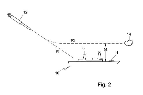
Figure 2 shows a schematic perspective view of the ship 10 equipped
with the soft-kill deployment system 1. The ship 10 is provided with multiple
sensors, such as an omn.i.-directional radar unit 11 for inputting data to the
computer system 3 of the soft-kill deployment system 1. Figure 2 further shows
a hostile missile 12 attacking the ship 10. When the missile 12 remains locked
on the ship 10, the missile 12 follows a path P1 and the missile 12 will hit
the
ship 10. However, if the soft-kill deployment system 1 works properly, the
missile will lock on a launched decoy 14 to follow another pre-determined path
P2 directed to the decoy 14 thereby missing the ship 10. The missile then
passes the ship 10 at a shortest distance, also called the miss distance M.
CA 02748832 2011-06-29
WO 2010/077142 PCT/NL2009/050837
The processor 4 is arranged for performing a number of steps. First
of all, the processor 4 signals an incoming missile 12. After signaling the
missile 12, the processor 4 performs an identifying step of the missile 12.
Such
an identifying step may include determining the missile type, position,
5 orientation, speed, path etc. In order to perform the identifying step
properly,
sensor data are input to the computer system 3 of the soft-kill deployment
system 1.
Figure 3 shows a time line t. Here, the subsequent symbols To, Ts
and Ti denote a launch time of the missile, the signalling time instant of the
missile and the identifying instant of the missile, respectively.
The processor 4 is further arranged for predicting a number of miss
distances associated with corresponding particular decoy launch parameters
sets. As an example, several tens of decoy launch parameter sets can be
evaluated, each of them corresponding to a particular miss distance. In the
predicting step, the use of an adjoint algorithm is included. The predicting
step
may be based on a large number of data, such as incoming missile parameter
data, mother platform parameter data, the corresponding decoy launch
parameter set and/or environmental data. Further, the processor is arranged
for selecting a decoy parameter set having an optimal predicted miss distance
M. The selected decoy parameter set is then transmitted to the launch unit 2
for launching the decoy. Further, control commands can be generated to
modiffr the position and/or orientation of the ship.
Optionally, the processor 4 is further arranged for performing the
step of computing uncertainty data corresponding with a predicted miss
distance, e.g. a probability area of the path that the missile is assumed to
follow.
In an embodiment according to the invention, the processor 4 selects
the decoy parameter set that corresponds to the largest predicted miss
distance M, thereby providing a largest offset between the ship 10 and the
missile 12. Alternatively, the processor also takes into account an
uncertainty
CA 02748832 2011-06-29
WO 2010/077142 PCT/NL2009/050837
6
in the predictions of the miss distance, thereby optionally selecting a decoy
parameter set that corresponds to a relatively large predicted miss distance M
having a relatively small -uncertainty.
Based on the selected decoy parameter set, the launch unit 2 of the
6 decoy system 1 launches a decoy 14 'including e.g. flare for influencing any
infra-red lock on device in the hostile missile and/or chaff for influencing
any
radar lock on equipment in the hostile missile. The decoy 14 is intended to
cause the missile to deviate from the original direction, away from the ship
10.
Referring to Fig. 3, the decoy 14 is launched at a time instant To.
Then, the missile lock on the decoy at a later time instant Tsp. At a further
time instant Tv, it is verified or validated whether the decoy works properly
and/or whether the missile 12 is now directed to the decoy 14. Thereto, the
processor 4 is also arranged for performing the substeps of predicting a zero-
effort miss distance, under platform lock on condition and decoy lock on
condition. As a result, using the adjoint algorithm, a zero-effort miss
distance
is computed assuming that the missile remains locked on the ship. The zero-
effor miss distance is dependent on a specific time instant and is defined as
the
miss distance which will result when at that specific time instant the path of
the ship and the missile will remained unchanged. Similarly, a zero-effor miss
distance is computed assuming that the missile changes lock on to the decoy.
The processor further performs the substeps of measuring data related to the
incoming missile and comparing the measured data with one or both predicted
zero-effor miss distances. Then, the processor deduces, from the comparison
results, on which entity the incoming missile is expected to be locked,
Preferably, the deducing step includes the use of computed uncertainty data
corresponding with a predicted zero-effort miss distance. After the validation
has been performed, the missile enters the miss distance area, closest point
of
approach, at time instant TCPA and moves away from the ship.
As a result, the predicting step can be used before launch of the
decoy, for finding an optimal launch parameter set. Further, after launch, the
CA 02748832 2011-06-29
WO 2010/077142 PCT/NL2009/050837
7
effectiveness of the soft-kill can be checked by comparing the predicted
effect if
the anti-ship missile has been lacked on the decoy or on the ship. The
decision
for the optimal decoy parameter set and/or the decision in the checking step
can be enhanced by using uncertainty data that may be provided by the
adjoint algorithm.
The adjoint algorithm, also known as adjoint method, is based on
making a single simulation of a modified model called the Adjoint Model in
order to determine the effect of all the perturbation sources that affect the
miss distance. The adjoint model can be readily obtained from a linearization
of the original model by performing some straightforward block diagram
manipulations. Alternatively, the adjoint model can be obtained easily from a
state-space representation of the original model. It can mathematically be
proven that for deterministically analyzing guidance loops, the separate
influence of the initial condition and of the input of the time-varying system
on
the final value of the output, it is enough to compute one initial-value
solution
of the adjoint system. Expressions can be derived for assessing the final
value
using an initial-value solution for an arbitrary initial condition and input.
Though if the Adjoint Method can be useful in the case of deterministic
performance analysis, it can be used with far greater advantage in the case of
stochastic performance analysis. To formulate the relevant mathematical
result it can be shown that the adjoint response can be used to compute the
variance of the output without lengthy Monte Carlo simulations.
As such, the adjoint method includes the steps of constructing an
adjoint model and using its response for generating performance data. The
adjoint model simulates the dynamical system whose response includes the
input sensitivities of the system to be analyzed. The adjoint algorithm is
thus
suited for evaluating the performance of the decoy process, in particular when
the process depends on many variables, is dynamic and time varying.
The initial configuration is represented by a guided antiship missile
that heads in the general direction of the ship at low altitude, a decoy cloud
CA 02748832 2011-06-29
WO 2010/077142 PCT/NL2009/050837
that is positioned a given displacement from the ship and moves freely with
the wind, and a ship that is assumed to keep a constant heading during the
engagement. At the start of the scenario it is assumed that the missile is
locked with its seeker on the decoy and uses the seeker data for computing
guidance commands. This assumption corresponds to the use of the decoy in
distraction mode. By contrast, in seduction mode, the missile is first locked
on
the ship itself and it changes lock to the decoy only after the decoy becomes
active.
It is assumed that the missile guides towards the decoy using
Proportional Navigation Guidance law until passing the decoy. Subsequently,
the missile continues in unguided flight until reaching the closest point of
approach with respect to the ship. During the entire engagement, the velocity
vector of the wind is assumed to be constant. It is also assLuned that the
missile speed is constant throughout the engagement, and consequently that
only the course of the missile changes as a consequence of guidance commands.
It is also assumed that the ship is performing an evasive manoeuvre
after deploying the decoy and that turning the ship towards the chosen course
may take some time.
According to an aspect of the invention, a non-linear model is
linearized to obtain a linear model. and an expression for the miss distance
can
be formulated depending on an acljoint response that is defused as the
solution
to an initial value problem. Further, the variance of the miss distance can be
expressed as a function of the variances of components of the initial
condition.
The variances of the initial state vector coordinates in terms of original
stochastic quantities can be approximated relatively easily. A post-launch
validation can be performed using statistical hypothesis testing algorithms.
CA 02748832 2011-06-29
WO 2010/077142 PCT/NL2009/050837
9
The motion of the. decoy is c1escribed as
(4.l) i:1 _ v.", . x1(0) _Xj.
Y"(0) = Jof
(d.4) 0 , V, (O)
The equations describing the motion of the ship are
(4.5) Xe = vzs(t) , x., 01) = X.,
(4.6) 1 a = uuJ9 (t) , ya (0) = yue,
where
(4.7) u.s (t) = V9 (t) cos &
(4.8) v,3 (t) = V& (t) sin 0.,
(4.9) () a, t < tman,
11 VJI'Max t > tman e
where tman is the time required to complete the manoeuvre of the ship.
The motion of the missile is described as
(4.10) V. Cos 0m , M. (0) = Xomt
(4.11) ym = V. sin 0m ym(0) = yam,
(4.12)m = VT-
an= -'.'-an + -an,c , an(0) = 0,
T
where T is the time constant of the missile describing the response of the
missile to
the guidance commands represented by the commanded lateral acceleration an,,.
For deployment planning purposes, it will be assumed that the missile is perma-
nently locked on the decoy, until it passes the decoy. In this case
I NPVV, fA, I lr~lf > 0,
(4.14) an,~ - 4, V_,! C d,
with Np, the navigation constant of the missile, VV, f, the closing velocity
between
missile and decoy, and A f, the angular rate of the line-of-sight between
missile
and decoy. If we use for the velocity vector of the missile the notation (v,m
=
Vm Cos 0m, v,m = Vm sin ¾7m), we have
Vt! (Xf - Xr)(Va f - yzm) + (yj - ym)(yy! - yum)
(4-15) Vj-(X f xm)!, +(yf-?1m)'-
A = (U- f - ysm)(yf -"' ym) - (yyf - yym)(xf "- xm)
(4.16) (X f - Zm)2 + (yf - ym)2
For the purpose of post-launch testing of the deployment effectiveness, it is
also
necessary to consider the case that the missile remains locked on the ship. In
this
case
(4.17) anx = NPVc,,a$,
where
(4.18) V (-Ta--Tm)(1 -ysm)+(y. -Yin) (y11,.....yym)
'l T.)2 + (d9 - Ym)7 1
(yxs - V..) (Y. - Y.) - (yyff yym)(X4 - xm)
~
(sa - Xm)2 + (yn - ym)-
CA 02748832 2011-06-29
WO 2010/077142 PCT/NL2009/050837
To linearize the nonlinear model described in the previous section, it is
convenient
to introduce a new coordinate system that we call the Engagement Coordinate
System, with the origin in the initial position of the missile, with the x-
axis along
the line-of-sight from missile to ship and the y-axis completing a positively
oriented
coordinate system. In Figure 3.1, the axes of this coordinate system are
denoted
XE and YE. The transformation between East-North coordinates and engagement
coordinates is defined by
cos Vsin 7P
(5.1) ~e = -sin 0 COS7P
where ib = aretan 2(yd, - Darn, xC5 xam)=
We denote by the superscript C all quantities expressed in engagement coordi-
nates. Accordingly, we have
(5.2) [TOT '1'c 17yjm r L' amJ "" Ti LV71m
and the analogues for the ship and decoy position and velocity vectors.
Since during the engagement, the course of the missile remains close to the
xC-axis, the velocity of the missile along the xC-axis is approximately
constant.
Also the range between missile and ship, and between missile and decoy can be
approximated by the difference of their x coordinates, whereas the miss
distances
can be approximated by the difference of their y coordinates. By neglecting
the
course variations of the missile, we can approximate the lateral acceleration
of the
missile by
(5.3) L4111 1 0 J
The angular rate of the line-of-sight to the decoy is approximated as
d [y! ym] (5.4) J` j = dt Rmj ,
where the relative range missile-decoy is R71 j(t) = VC, j(t,isg, j - t). We
obtain
(5.5) J1 j - y j - yf, + (yy,,, - yprn)(t~ iss,f - t)
...- t)
~crj(tmiss,f
In a similar fashion, the line-of sight to the ship is approximated as
73 ym
where Rms(t) = ue,s(tniss - t). Consequently,
(5.7) ,`s = ys - ym * lye _ ~ymll~miss J t)
Vc,s (tiss - t) ..
Rom the condition that y ;, = x! at time tõ~is5, j, we deduce that
Xe
(5.8) of tmiss,j C c
vxon, - " :,,,
CA 02748832 2011-06-29
WO 2010/077142 PCT/NL2009/050837
11
The time of !Right to the closest point of approach with respect to the ship
can be
approximated from the condition that x;ti = x; as
xaA
(5.9) tmiss = ve -
xam xaA
In conclusion, the linearized model for the case that the missile is locked on
the
decoy has the form /
yTTI. - uym Ym(0) - Y.,.,
an s vym(0) = vyami
Qn = -1an+1an,c, an(0)=0,
T T
(5.10) (tmi. -0:1 [l~f - ym (vu. - Ucym)(tmiAS, j _ t))L t < tmi9sj,
t (0, t
1 ~f /r5} a~ > tmi-sx,f 1
7~9 v]jS(t) 1 .Y (}1u/-// :1a91
y~ - vyw , j/ (") = daf )
vuw o vyw (0) - vyow'
In the case that the missile is locked on the ship, equation (5.10) is
replaced by
(5.11) an,c = (t,nzNP t)2 [CJs - Ym + (vas - vym)(tmiss - t)),
and the equations describing the motion of the decoy may obviously be skipped
as
they do not influence the outcome of the engagement.
In both cases, the resulting model is a linear, time-varying system on [0,
tj}.
The miss distance with respect to the ship is approximated by
(5.12) Miss = ym (tm{aA) - ye (tmiss),
which is a linear function of the state of the linearized model.
For the post-launch effectiveness assessment, we use the Zero-Effort-Miss dis-
tance that can be calculated at each time moment t during the engagement as
(5.13) z = v ,, - Y8 + (trniss - t) (vym - vys),
Notice that the miss distance is equal to z(tmji4).
It is still necessary to modify the linearized model to suit our application.
In-
deed, it is easy to see that the model (5.10) is singular at time t = tni,s,
j. A
straightforward way to eliminate this singularity while preserving the
linearity of
the model, by introducing a "blind time" tG > 0 that is a small interval
before
passing the decoy ia which the missile shuts down its guidance loop. With this
change, the expression of the commanded acceleration for the case that the
missile
is locked on the decoy becomes
arts=
(5.14) (i-, ,l-t) [U ym + M. - vim) [t, ti s, j - t)] , t < tmu., j - tt,o
0, t? tmiss,j th
A similar change is necessary for the case that the missile is locked on the
ship.
Notice that the introduction of the "blind time" is not necessarily affecting
the
realism of the simulation. Most antiship missiles are turning off the seeker
when in
CA 02748832 2011-06-29
WO 2010/077142 PCT/NL2009/050837
12
the immediate vicinity of the target, This is done in order to avoid confusing
the
seeker when the target is too large in relation to the field of view.
If we introduce the state vector x = ~y~, vim a, y9 yf uu~~T the lin-
earized model can be written in matrix form as
(6.1) x = A(t)x+w(t),
where
0 1 0 0 4 0
a 0 1 0 0 0
(6.2} A(t) = ci(t) (t) - z 0 C3 (t) c4(t)
0 0. 0 0 0 0 '
0 0 a 0 0 1
0 0 a 0 0 0
0
0
(6.3) w(t) 0
VO (t}
0
0
with
N t<t t
-03 b a) c3 (t) = r(1-; t miss, f - b t
1 0, t > t,niss, f ."" tbt
- N, t< -
(6.5) Cg (t) T(tmine,l^t)t miss,f tit
O! t 2: tmi9, f - ibt
Nn
(6.6) c (t) = T(tmif-~}s t < tmissj - tbi
0, t 2: tmis9, f - tb t
-'-- t < t t h,
ci(t) - rttmias,~^t~ I mi55,f - b,
0, t > tmiss,j - tb,
and the initial condition is x(0) = [0 vyom 0 0 Ay; v,'] T. The miss distance
can be written as
(6.8) Miss = [1 0 0 -1 0 0] x(tmiss)=
The adjoint response at time t,,,iõ is the solution of the equation
(6.9) Xad} = AT(tmi,, - t)xadj
with initial condition x d'(0) _ [1 0 0 -1 0 01T. Notice that since matrix
B in (6.1) is the identity, the state and output adjoint responses coincide.
CA 02748832 2011-06-29
WO 2010/077142 PCT/NL2009/050837
13
According to Proposition 2.1, the miss distance can be written as
r~ nis^
(6.10) Miss = xad~(tmisa)Tx(0i) ( [xadj(trniss T)I2 w(T)dr
iM iaa
2 c a d7 e
_ X2 1 (tmsss)VUam + 8 (amiss - T) UUS(T)dT
+ Z5da (tmias)~yf + Csd1 (tmiss)T11w
This form is particularly interesting for deterministic performance studies.
In case
that the initial data contains uncertainties with a stochastic character,
Proposition
2.2 can be used to estimate the variance of the miss distance as a function of
the
variances of the components of the initial condition
2 ndj T add
(6.11) ~A4isa - X (am
rriss) Px(q)x [X- a)
!21dI (tmissj320y + d]( 1
tCltSaS Ir
2 2mam+
adj j22 add 2- 2
( 5 (tmigs3 0 67,f
+ T LAG (~miss~ WW1
where P,,{G) denotes the variance matrix of x(0). Since the input of the
system
(6.1) is deterministic, the integral term in formula (2.6) does not appear in
(6.11).
Notice that formula (6.11) contains also the term corresponding to yom that
does
not occur in (6.101) since yam = 0 by the choice of the coordinate system, but
its variance might be non-zero, reflecting uncertainties in the track data
available
about the missile. Notice also that formula (6.11) in its matrix farm is more
general
since it may also contain crossvariance terms as well.
To apply formula (6.11) in practice, it is still necessary to determine the
variances
of the initial state vector coordinates in terms of the original stochastic
quantities.
An exact solution to this question may be difficult to obtain analytically,
but for-
tunately it is easy to write approximations for these variances that are
practically
acceptable. For example, let us assume that xorn and yam are stochastic
variables
of mean aa,, and ya,T, and variances and aynõ,. Then the variance of yam is
obtained as the (2,2) element of the matrix
2
T1.
(6.12) Ta _*n m
an
If the error in tracking the course of the missile q1m comes with a variance
up,,
then the variance of vvam is approximately
{6.13) CTVunm V
=m0 1.
This relation does not take into account the error in the tracking of the
missile total
velocity. If we want to examine the effect of the dispersion of the decoy
cloud, and
we model it as a random perturbation on the launch direction, then the
variance
of yp f can be approximated as
(6.14) cFunf Dfcr,pf.
These estimates were used for the numerical tests with good results. In
general,
more complicated relations might be necessary to evaluate the terms occuring
in
(6.11).
CA 02748832 2011-06-29
WO 2010/077142 PCT/NL2009/050837
14
Let us assume now that the decoy was launched and that at a fixed moment of
time td it is required to determine whether the deployment was successful,
that is if
the missile has locked on the decoy. In case of an active missile there are
essentially
two ways to perform this function (see [1]). The first applies to active and
passive
missiles as well and is based on computing the closest point of approach of
the
attacking missile. The second way to assess if the attacking missile is locked
on the
ship is based on using the ESM system indication to measure the radar signal
used
by the missile to track the ship. The second method is considered more
reliable as
it will also work if the missile performs a dogleg manoeuvre such that the
apparent
closest point of approach may appear to be very far away. However, as
mentioned
before, the first method is more widely applicable and, as reported in [1],
none of
the methods outwits the other in all the possible situations.
In this section we will show how the Adjoint Method can be used to refine the
first method of assessing the success of launching the decoy based on the
closest
point of approach. The idea is to use the Adjoint Method to estimate the
closest
point of approach for both the case that the missile is locked an the decoy
and the
case that the missile is locked on the ship. By comparing the computed
position
based on track data with these estimates and taking into account the variances
of these estimates that can equally be determined using the Adjoint Method, it
is
possible to decide whether the missile has indeed locked on the decoy or not.
The linearized model in the case that the missile is locked an the decoy was
in-
troduced in the previous section as equation (6.1) and the following. The
linearized
model in the case that the missile is locked on the ship has the same form as
(5.1),
with x = [y;,, vy,n an V.,, (t)] and
0 1 Ãl Ãl
0 0 1 0
(7 1) A(t) = cj(t) c2(t) -r 0
0 0 07 Q
0 0 0 0
0 0 0 0
where
(7.2) r-1(t) = JVV
.
T(t.. ill õ t)
(7.3) c2(t) = - NP
T(tmiss - t)
and the initial condition is x(0) = [0 v'om 0 0 Ay; vw] T. We are interested
in the value of the Zero-Effort-Miss distance introduced in (5.13) at time td
that
can be written as
(7.4) Z = [1 tmiss - t 0 --1] x + [0 0 0 --tmisa + t] w(E).
Clearly, the linear model has the form (2.1) with D not identical zero. To
apply
Proposition 2.1, let the adjoint response be defined as the solution to the
initial
value problem
(7.5) kaLj = AT (td .... t)xndj
CA 02748832 2011-06-29
WO 2010/077142 PCT/NL2009/050837
'with initial condition xadf (0) = [l tm.iss - td 0 --11 T_ We have
(7.6)
Z(td) xadj (td)T x(Q)+f [x`j(td T)]Tw(r)dr+ [0 0 0 trrriss + td1 W(td)
1 In l
t
= X2di (td)vgnrn + j xdd (td - T)v s (r)dr r (miss - td)vpa (td)=
0
Since the velocity of the ship is not a stochastic variable, the presence of
the D
term in the linear model does not have any influence on the formula for the
variance
of the Zero-Effort-Miss distance, According to Proposition 2.2
n T nd a111]20-2.
(7.7) v! = x cr(td) P,,l0lx 1(td) = I (td [ 2 (td]2 uui<nm,
In a similar fashion, the Adjoint Method can be applied to estimate the Zero-
Effort-Miss distance at time td in case that the missile is locked on the
decoy.
We denote by z, and by rr, the average and the variance of the miss distance
assuming that the decoy launch was successful and the missile is locked on the
decoy, and by z f and by a f the average and the variance of the miss distance
assuming that the decoy launch failed to distract the missile from the ship.
The value of the Zero-Effort-Miss distance at time td can also be computed
based
on track data, and this value is denoted z. We assume that 2 is normally
distributed
around z, the "true" (based on true geometrical data) ZEMD with variance u,,,
that
can be evaluated based on the accuracy of measurement data that are involved
in
computing i.
The theory of statistical hypothesis testing can be used to provide an optimal
interval Z, \(z,, z f, a , v f, arm) such that if
2eZa,
then the best decision is that the missile is locked on the decoy, and if this
condition
is not satisfied then the best decision is that the missile is locked on the
ship. The
optimal interval Z), can be obtained from the Neyman-Pearson Lemma. For con-
ven.ience, we summarize here the main notions and results of statistical
hypothesis
testing that we use in the sequel.
First of all, let the null hypothesis He be that "the missile is locked on the
decoy"
and the alternate hypothesis Hl be that "the missile is locked on the ship".
In this
case, the type I probability, or the probability of false alarm is that the
hypothesis
HL is accepted, whereas Ha is true:
(7.8) ' Par = P{"HI'Vu},
The type II probability, or the probability of miss is that the hypothesis He
is
accepted, whereas HZ is true:
(7.9) P.Ir = P{"Ha IHF}.
The power of the test is defined as
(7.10) 7r = P{"Hi'1HI} = I - Parl-
The problem is to determine the decision interval Z,\ that maximizes the power
of the test, or minimizes the probability of miss, such that the probability
of false
alarm takes a given value a. The following classical result can be used to
determine
the optimal threshold.
CA 02748832 2011-06-29
WO 2010/077142 PCT/NL2009/050837
16
The Neyman-Pearson Lemma: The optimal decision that minimizes the
probability of miss subject to a given probability of false alarm a is
obtained by
the following criterion based on the likelihood ratio
(7.11) A(Hi, Ho) = p( IH^/ > A [1 LT~
C Afl a~r
where Z represents the observation, and where Ao satisfies
(7.12) P{A(Hl,, Ho) > A0I H0} = a.
In our application, the observation is represented by the computed ZEMD E.
Assuming that all the prediction errors are normally distributed, with the
notations
introduced before we have
7 Qua ~p~
(7.13) p(il Ha) = 1 e t
27r(ff8 + 0-rn,)
and
1 _ c
(7.14) p(zIHI) = e f
2n(rr f + am)
and therefore, the likelihood ratio is
ffg+am 7 nfpm J~6Rt
(7.1.5} A{H~IHc} - e
of + a ,
After some straightforward manipulations, the condition A(H1IHe) > Aa is equiv-
alent to
1 1 Z, o f
i- X
a9+91 fff +ff Qy+i'am fff +am
1 1 _ Z. zf
rr2 + an, + of { ag + am + of + ffm
oaf+o-
(7.1fi) > 1nA o a +. Qa
a M
The probability that this condition is satisfied can be evaluated using the
assump-
tion about the conditional distribution of 2 if Hp is true. According to the
Neyman
Pearson Lemma, this probability has to be equal to a and h.0 can be computed
using
this condition.
The solution i8 particularly simple for the case that a f = ag = a. In this
case,
the previous condition is equivalent to
(7.17) (zf--z&)(~--i ~zf)>(a+an}1nAa.
Assume that z, > z f which is physically the most likely case, since it is
expected
that a successful lock on the decoy will lead to a larger ZEMD than if the
missile
is locked on the ship. Then the previous relation is equivalent to
zs+af a +aT, InAa.
2 ZS - zf
CA 02748832 2011-06-29
WO 2010/077142 PCT/NL2009/050837
17
Now we can evaluate the conditional probability in the Neyman-Pearson Lemma
using the conditional distribution of 2. We have
P{A(H1, Ho) > A0[H0}
In A
771477 ~rr~'-) e ' a +um dz
= NormCDF( Z f - ZS Q2 -+01 in A0),
2 VP- zp - zf
where NormCDF stands for the cumulative distribution function of the standard
normal law
(7.20) NormGDF(71) = 1 J d6.
From the Neyman-Pearson lemma, we can readily obtain the value of AD by
equating
the expression (7.19) to the false alarm rate iy. We obtain
- I)) -- Norn,CDF--1(a)
~{a '~QTLI
(7.21) -:--
.21) AD = e
Introducing this expression in (7.18), we deduce that the optimal decision
criterion
for accepting hypothesis Hi is that
(7.22) z < zs + NormCDF-1(c,) Q2 + am.
The power of this criterion can be obtained by evaluating the probability that
this
condition is satisfied in case that Hl is true. Given the conditional
distribution of
z, we conclude that
(7.23) 7r = P{"Hi [HL} = NormCDF( z'- zf +NormCDr,-1(o))
a2 + a-;,,
In the general case, that c f ag, it is impossible to obtain closed-form ex-
pressions for the optimal decision criterion. However it is possible to
propose a
numerical algorithm that uses the conditional averages and variances to
perform
the decision. We explain this algorithm for the case that of > a, With the
notations
(7.24) zl = i t
oil m - 1-}- n,
zf
(7.25) z2 = 1 i ,
(0-s+am~2+0.2 Inlipa
(7.26) C = 2
n
oUa
it is easy to see that relation. (7.16) can be rewritten as
(7.27) (z - zl)(2 - z2) > C.
The problem of determining AD to satisfy the condition of the Neyman-Pearson
Lemma reduces to the problem of finding C such that
(7.28) P{(i - zl)(z - Z2) > C[Ho} = a.
CA 02748832 2011-06-29
WO 2010/077142 PCT/NL2009/050837
18
With this value of 0, if the estimate of the Zero Effort Miss distance 2
satisfies
(7.27), then H1 will be accepted, and otherwise H0 will be accepted.
Introducing further
(7.29) 2 = Z1 2 z2
2
(7.30) Cr = ( Z1 2 Z2 ) + C,
the two solutions of the second degree equation
(7.31) (2 - Z1.)(2 - a2) = C
are
(7.32) 21,2 = 2 f C'.
Notice that these two solutions are the limits of the decision interval Z..
Relation
(7.2B) is equivalent to
(7.33) 1 NarmCDF( Qy +Q~ )3 NormCDF( v2 +~2
s m rrc
or equivalently
1-NormCDF( Z - Z + C' +
a';TQm rr3+cr,
(7.34) NormCDF( z - Z' C' ) = a.
U:+ala8+O'rn
This equation reduces to solving the nonlinear equation in x = C j
u, +v,,,
(7.35) 1--- Norm.CDF (A + x) + NormCDF (A - x) = a,
where A is a known parameter. This equation has a unique positive
solution for every value of A and a in the interval (0, 1) since the function
on the
left hand side is strictly decreasing in x, takes the value I for s = 0 and
converges
to 0 for x -+ o . Moreover, it is easy to find upper and lower bound for the
solution-
For example, if A > 0, it is easy to see that
(7.35) 1 - NormCDF(A + x) < NormCDF(A - x)
for each x > 0. Now let
(7.37) xl = A _ NormCDF 1(a),
2
(7.3B) x2 = NormCDF-1(1- 2-)-A.
Assume that both x1 and x2 are positive, which is generically true for small
values of
a. Remember that a is the false alarm rate and it is usually chosen to be very
small.
Using inequality (7.36), it becomes clear that the left hand side of (7.35) is
greater
than a for x = xl and it is smaller than a for x = x2. Because of
monotonicity,
the solution of (7.35) is guaranteed to be in the interval (xi, x2). Using a
bisection
method, the solution can be easily determined. This provides the solution C'
for
the equation (7.34), which can be used to determine C from (7.30), which in
turn
is used to check the decison criterion to determine if the antiship missile is
locked
CA 02748832 2011-06-29
WO 2010/077142 PCT/NL2009/050837
19
-Ire C Para.1320ter Sy]Tll)Ul F'alne
Target sensor Missile iniitial. Eat [777] 6000
Missile initial North lit 6000
1 Iis;ile velocit}- m/s 1117 300
E5tiina to c of missile initial East 171
c7 of Missile ilaitial North [n1] LTt 40.3
!i of missile inlithll r_Uurse [lELcll -T,i0.08
Missile time coustau [s] r 0.1
Missile navigation constant: 3
ltlissilc blind time [s] t . 0.3
Wind ebocity ln;`s l=;jo 10
Wind Course Jrad (" I 11L, TI
i7 of wind course rad .0
Own platfurnl Ship initial East, [nu] I)
whip initial North [ill] ?!,,,,,. I)
Ship velocity [111/'s] 9
ship course [rad] ;/ate 37,-/ ~}
Decoy relative distance [m] A '2 DO
Decoy leutnch direction rr'acl i,',} 3.927
Shill inauoeiLVre rlela~t s t
nx,a n
C`_i~L I-rL 1. ' acties at t e parameters }.used in tie numeric:a experiments
on the ship, or on the decoy according to relation Moreover , the power of
the criterion Fi- = F' "If j'~F 1 F can be cornputecl as
i ,3 11 = 1 - Norm GDF( .tr -+ -yorm(-!DF ,Tr n
IV.
::here! and are given by (7. 3 21.
The prediction using the adjoint algorithm may thus be applied in
two ways. Firstly, before launch, the prediction may be used to optimize the
deployment. Secondly, after launch, the prediction may be used to make an
assessment on the success of deployment. The latter may be realized by
comparing observations and predictions of the closest point of approach under
two hypotheses: that the missile is locked on the decoy, i.e. the deployment
was
succesful, and that the missile is locked on the ship, i.e. the deployment
failed.
The fact that the Adjoint Method can take into account measurement and
CA 02748832 2011-06-29
WO 2010/077142 PCT/NL2009/050837
estimation .uncertainties without excessive computational effort leads to
advantages, especially for the success assessment.
The method of applying soft-kill deployment to mislead an incoming
missile directed to a mother platform can be performed using dedicated
5 hardware structures, such as FPGA and/or ASIC components. Otherwise, the
method can also at least partially be performed using a computer program
product comprising instructions for causing a processor of the computer system
to perform the above described steps of the method according to the invention.
All steps can in principle be performed on a single processor. However it is
10 noted that at least one step can be performed on a separate processor, e.g.
the
step of identifying a hostile missile and/or the step of identifying the
missile.
Figure 4 shows a flow chart of an embodiment of the method
according to the invention. A method is used for applying soft-kill deployment
to mislead an incoming missile directed to a mother platform. The method
15 comprises the steps of predicting (100) a number of miss distances
associated
with corresponding particular decoy launch parameter sets, selecting (110) a
decoy parameter set having an optimal evaluated miss distance; and
transmitting (120) the selected decoy parameter set to a launch unit for
launching the decoy. The predicting step (100) includes the use of an adjoint
20 algorithm.
It will be understood that the above described embodiments of the
invention are exemplary only and that other embodiments are possible without
departing from the scope of the present invention. It will be understood that
many variants are possible.
The soft-kill deployment system according to the invention may be
provided with a single launch system or with a multiple launch system.
Further, a single missile or a multiple number of missiles directed to the
mother platform can be coped with by the soft-kill deployment system
according to the invention.
CA 02748832 2011-06-29
WO 2010/077142 PCT/NL2009/050837
21
Though in the embodiments described above the method according
to the invention is applied in combating an antiship missile threat, the
method
can also be applied when coping with missiles directed to other mother
platforms, such as missiles threatening an airplane or a ground vehicle.
Such variants will be obvious for the person skilled in the art and
are considered to lie within the scope of the invention as formulated in the
following claims.