Note: Descriptions are shown in the official language in which they were submitted.
CA 02749057 2011-08-10
WO 2005/081842 PCT/US2005/004953
SYSTEM FOR DELIVERING CONFORMAL RADIATION THERAPY
WHILE SIMULTANEOUSLY IMAGING SOFT TISSUE
Inventor: James F. Dempsey
University of Florida
(UF Disclosure No. 11413)
AKERMAN SENTERFITT DOCKET NO. 5853-484
1
CA 02749057 2011-08-10
WO 2005/081842 PCT/US20051004953
SYSTEM FOR DELIVERING CONFORMAL RADIATION THERAPY
WHILE SIMULTANEOUSLY IMAGING SOFT TISSUE
CROSS-REFERENCE TO RELATED APPLICATIONS
[0001] This application claims priority to U.S. Provisional Patent Application
No.
60/546,670, which was filed February 20, 2004.
STATEMENT REGARDING FEDERALLY SPONSORED
RESEARCH OR DEVELOPMENT
[0002] Not applicable.
FIELD OF THE INVENTION
[0003] This invention relates to a radiotherapy system and method, more
particularly a radiotherapy system and method for rapidly and repeatedly
imaging the
anatomy of a patient during the moments that dose is delivered to the patient
during
radiation therapy so that the actual ionizing radiation dose delivered to the
patient in
portions over a course of many days or weeks may be determined and the therapy
may
be adjusted to account for any treatment delivery errors caused by organ
motions or
changes in patient geometry. The magnetic resonance imaging method employed in
this
invention also improves the soft tissue contrast over the existing x-ray
computed
tomography (CT) imaging and may provide additional metabolic and physiological
information to improve target delineation and allow for the monitoring of the
response
of the patient or disease to therapy.
BACKGROUND OF THE INVENTION
[0004] In treating disease caused by proliferative tissue disorders such as
cancer
and coronary artery restenosis with radiation, the portions of the patient
known to
(WP218792;4)
2
... .. ... _. .. _..~.-.....-..ns ,v+w. :.....u...r.-.--. ,. .+m -.ice. tee.
_e.v..._... rope e -..wa?.. .. ...±rr... a.w9.aw . _ ........,.__ _... ..._-
...._-y_ ... ._,. _NNUiu
CA 02749057 2011-08-10
WO 2005/081842 PCT/US2005/004953
contain or suspected to contain disease are irradiated. For this purpose, a
radiotherapy
planning system is used to first acquire planning images of the diseased
portion(s) and
surrounding regions.
[0005] Radiotherapy planning systems generally include a CT or magnetic
resonance imaging (MRI) simulator. CT or MRI radiography is carried out on a
single
day before the beginning of therapy to acquire a plurality of coregistered
sectional 2-D
images. These sectional images are combined using known algorithms to produce
3-D
images. These 3-D simulation images are displayed and then analyzed to
identify the
location of regions of suspected disease to be treated, such as a
radiographically evident
tumor or regions suspected of microscopic disease spread. These regions to be
treated
are called radiotherapy targets. In order to attempt to account for organ
motions, the
concept of margins and planning target volumes (PTVs) was developed to attempt
to
irradiate a volume that would hopefully contain the target during most of the
irradiation.
PTVs include a geometric margin to account for variations in patient geometry
or
motion. Likewise, the 3-D simulation images are displayed and then analyzed to
identify important normal anatomy and tissues that may be damaged by the
radiation,
such as the spinal cord and lung, to evaluate the potential impact of
radiation on the
function of these tissues. These regions to be spared or protected from
excessive
radiation are called critical structures or organs at risk and may also
include a margin to
account for variations in patient geometry or motion. The delivery of
radiation therapy
is then traditionally planned on a single static model of radiotherapy targets
and critical
structures derived from a single set of CT and/or MRI images. Because the
known art
does not allow for simultaneous imaging and therapy, the patient and all of
their internal
organs need to be repositioned exactly for accurate dose delivery. However, it
is known
in the art that exactly repositioning the patient even for a single delivery
of dose is not
possible due to several factors including: the inability to reproduce the
patient setup,
i.e., the geometry and alignment of the patient's body; physiological changes
in the
patient, such as weight loss or tumor growth and shrinkage; and organ motions
in the
patients including but not limited to breathing motion, cardiac motion, rectal
distension,
peristalsis, bladder filling, and voluntary muscular motion. Note that the
organ motions
may occur on rapid time scales such that changes may occur during a single
dose
delivery (e.g., breathing motion), termed "intra-fraction" organ motions, or
they may
WP218792;4} 3
CA 02749057 2011-08-10
WO 2005/081842 PCT/US2005/004953
occur on slower time scales such that changes occur in between dose
deliveries, termed
"inter-fraction" organ motions. Much of the curative treatment of patients
with cancer
outside the cranium requires the delivered radiation therapy to be
fractionated, i.e., the
dose is delivered in many fractions. Typically, dose is delivered in single
1.8 to 2.2 Gy
fractions or double 1.2 to 1.5 Gy fractions daily, and delivered during the
work week
(Monday through Friday); taking 7 to 8 weeks to deliver, e.g., a cumulative
dose of 70
to 72 Gy at 2.0 or 1.8 Gy, respectively. A purpose of this invention is to
overcome the
limitations imposed on radiation therapy by patient setup errors,
physiological changes,
and both infra- and inter-fraction organ motions throughout the many weeks of
radiation
therapy. Another purpose is to allow the physician to periodically monitor the
response
of the patient's disease to the therapy by performing MRI that provides
metabolic and
physiological information or assessing the growth or shrinkage of gross
disease.
[0006] An irradiation field shape is then determined to coincide with an
outline of
an image of the target's diseased regions or suspected regions appearing in
the planning
images. An irradiating angle is determined from sectional images of a wide
region
including the diseased portion or a transmitted image, seen from a particular
direction,
produced by the 3-D simulation images. A transmitted image seen from the
irradiating
angle is displayed. The operator then determines a shape of an irradiation
field on the
image displayed, and sets an isocenter (reference point) to the irradiation
field.
[0007] Optionally, the patient may be positioned relative to a conventional
simulator (ortho-voltage X-ray imaging system that allows portal images to be
generated for radiation therapy setup). An irradiating angle corresponding to
the
irradiating angle determined as above is set to the simulator, and an image is
generally
radiographed on a film through radiography for use as a reference radiograph.
Similar
digitally reconstructed radiographs may be produced using CT or MRI simulation
software.
[0008] The patient is then positioned and restrained relative to a radiation
treating
apparatus which generally includes a radiation source, typically a linear
accelerator. An
irradiating angle is set to the irradiating angle determined as above, and
film
radiography is carried out by emitting radiation from the radiation treating
apparatus.
This radiation film image is correlated with the above film image acting as
the reference
radiograph to confirm that the patient has been positioned according to plan
as correctly
(WP218792;4) 4
CA 02749057 2011-08-10
WO 2005/081842 PCT/US2005/004953
as possible before proceeding with radiotherapy. Some repositioning is
generally
required to place the patient such that the structures in the reference
radiograph match
the structures in the treatment radiograph to within a tolerance of 0.2 to 0.5
cm. After
acceptable patient positioning is confirmed, radiotherapy is begun.
[0009] Patient setup errors, physiological changes, and organ motions result
in
increasing misalignment of the treatment beams relative to the radiotherapy
targets and
critical structures of a patient as the radiotherapy process proceeds. For
years
practitioners have been acquiring hard-copy films of the patient using the
radiation
therapy beam, technically referred to as a "port film" to attempt to ensure
that the beam
position does not significantly vary from the original plan. However, the port
films
acquired are generally only single 2-D projection images taken at some
predetermined
interval during the radiotherapy process (typically 1 week). Port films cannot
account
for organ motion. Additionally, port films do not image soft tissue anatomy
with any
significant contrast and only provide reliable information on the boney
anatomy of the
patient. Accordingly, misalignment information is only provided at the
instants in time
in which the port images are-taken and may be misleading as the boney anatomy
and
soft tissue anatomy alignment need not correlate and change with time. With
appropriate markers in the port image provided, the beam misalignment may be
determined and then corrected to some limited degree.
[00010] More recently, some have disclosed acquiring the port images
electronically, referred to as electronic portal imaging. This imaging
technique employs
solid state semiconductor, scintillator, or liquid ionization chamber array
technology to
capture x-ray transmission radiographs of the patient using the x-rays of the
linear
accelerator or an associated kilovoltage x-ray unit. As with the hard-copy
technique,
misalignment data is only provided at the instants in time in which the port
images are
taken. Another recent advance in electronic portal imaging includes the use of
implanted interstitial radio-opaque markers that attempt to image the location
of soft
tissues. These procedures are invasive and subject to marker migration. Even
when
performed with the rapid acquisition of many images, it only finds the motion
of
discrete points identified by the radio-opaque markers inside a soft tissue
and cannot
account for the true complexities of organ motions and the dosimetric errors
that they
cause. Another recent advance, that creates 3D volumetric image sets from many
2D
(WP218792;4) 5
CA 02749057 2011-08-10
WO 2005/081842 PCT/US2005/004953
electronic portal images, is the acquisition of volumetric cone-beam x-ray CT
or helical
tomotherapy megavoltage x-ray CT image set before or after the daily delivery
of
therapy. While this technology may account for patient setup errors, i.e., the
geometry
and alignment of the patient's body, physiological changes in the patient,
such as
weight loss or tumor growth and shrinkage, and inter-fraction organ motions in
the
patient, such as rectal filling and voiding; it cannot account for intra-
fraction organ
motions in the patients. Intrafraction organ motions are very important and
include, but
are not limited to, breathing motion, cardiac motion, rectal gas distension,
peristalsis,
bladder filling, and voluntary muscular motion.
[00011] Radiation therapy has historically been delivered to large regions of
the
body including the target volume. While some volume margin is required to
account
for the possibility of microscopic disease spread, much of the margin is
required to
account for uncertainties in treatment planning and delivery of radiation.
Reducing the
total volume of tissue irradiated is beneficial, since this reduces the amount
of normal
tissue irradiated and therefore reduces the overall toxicity to the patient
from radiation
therapy. Furthermore, reduction in overall treatment volume may allow dose
escalation
to the target, thus increasing the probability of tumor control.
[00012] Clinical cobalt (Co60 radioisotope* source) therapy units and MV
linear
accelerators (or linacs) were introduced nearly contemporaneously in the early
1950's.
The first two clinical cobalt therapy units were installed nearly
simultaneously in
October of 1951 in Saskatoon and London, Ontario. The first MV linear
accelerator
installed solely for clinical use was at Hammersmith Hospital, London England
in June
of 1952. The first patient was treated with this machine in August of 1953.
These
devices soon became widely employed in cancer therapy.. The deeply penetrating
ionizing photon beams quickly became the mainstay of radiation therapy,
allowing the
widespread noninvasive treatment of deep seated tumors. The role of X-ray
therapy
slowly changed with the advent of these devices from a mainly palliative
therapy to a
definitive curative therapy. Despite similarities, cobalt units and linacs
were always
viewed as rival technologies in external beam radiotherapy. This rivalry would
result in
the eventual dominance of linacs in the United States and Western Europe. The
cobalt
unit was quite simplistic and was not technically improved significantly over
time. Of
course, the simplicity of the cobalt unit was a cause for some of its appeal;
the cobalt
{ WP218792;4} 6
CA 02749057 2011-08-10
WO 2005/081842 PCTIUS2005/004953
units were very reliable, precise, and required little maintenance and
technical expertise
to run. Early on, this allowed cobalt therapy to become the most widespread
form of
external beam therapy. The linac was the more technically intensive device.
Accelerating high currents of electrons to energies between 4 and 25 MeV to
produce
beams of bremsstrahlung photons or scattered electrons, the linac was a much
more
versatile machine that allowed more penetrating beams with sharper penumbrae
and
higher dose rates. As the linac became more reliable, the benefits of having
more
penetrating photon beams coupled with the addition of electron beams was seen
as
strong enough impetus to replace the existing cobalt units. Cobalt therapy did
not die
away without some protests and the essence of this debate was captured in a
famous
paper in 1986 by Laughlin, Mohan; and Kutcher which explained the pros and
cons of
cobalt units with linacs. This was accompanied by an editorial from Suit that
pleaded
for the continuance and further technical development of cobalt units. The
pros of
cobalt units and linacs have already been listed. The cons of cobalt units
were seen as
less penetrating depth dose, larger penumbra due to source size, large surface
doses for
large fields due to lower energy contamination electrons, and mandatory
regulatory
oversight. The cons for linacs increased with their increasing energy (and
hence their
difference from a low energy cobalt beam), and were seen to be increased
builddown,
increased penumbra due to electron transport, increased dose to bone (due to
increased
dose due to pair production), and most importantly the production of photo-
neutrons at
acceleration potentials over 10 MV.
[00013] In the era before intensity modulated radiation therapy (IMRT), the
linac
held definite advantages over cobalt therapy. The fact that one could produce
a very
similar beam to cobalt using a 4MV linac accelerating potential combined with
the
linac's ability to produce either electron beams or more penetrating photon
beams made
the linac preferable. When the value of cobalt therapy was being weighed
against the
value linac therapy, radiation fields were only manually developed and were
without the
benefit of IMRT. As IMRT has developed, the use of higher MV linac
accelerating
potential beams and electron beams have been largely abandoned by the
community.
This is partly due to the increased concern over neutron production (and
increased
patient whole body dose) for the increased beam-on times required by IMRT and
the
complexity of optimizing electron beams, but most importantly because low MV
{ WP2] 8792;4} 7
CA 02749057 2011-08-10
WO 20051081842 PCT/US2005/004953
photon-beam IMRT could produce treatment plans of excellent quality for all
sites of
cancer treatment.
[00014] IMRT represents a culmination of decades of improving 3D dose
calculations and optimization to the point that we have achieved a high degree
of
accuracy and precision for static objects. However, there is a fundamental
flaw in our
currently accepted paradigm for dose modeling. The problem lies with the fact
that
patients are essentially dynamic deformable objects that we cannot and will
not
perfectly reposition for fractioned radiotherapy. Even for one dose delivery,
intra-
fraction organ motion can cause significant errors. Despite this fact, the
delivery of
radiation therapy is traditionally planned on a static model of radiotherapy
targets and
critical structures. The real problem lies in the fact that outside of the
cranium (i.e.,
excluding the treatment of. CNS disease using Stereotactic radiotherapy)
radiation
therapy needs to be fractionated to be effective, i.e., it must be delivered
in single 1.8 to
2.2 Gy fractions or double 1.2 to 1.5 Gy fractions daily, and is traditionally
delivered
during the work week (Monday through Friday); taking 7 to 8 weeks to deliver a
curative dose of 70 to 72 Gy at 2.0 or 1.8 Gy, respectively. This daily
fractionation
requires the patient and all of their internal organs to be repositioned
exactly for
accurate dose delivery. This raises an extremely important question for
radiation
therapy: "Of what use is all of the elegant dose computation and optimization
we have
developed if the targets and critical structures move around during the actual
therapy?"
Recent critical reviews of organ motion studies have summarized the existing
literature
up to 2001 and have shown that the two most prevalent types of organ-motion:
patient
set-up errors and organ motions. While significant physiological changes in
the patient
do occur, e.g., significant tumor shrinkage in head-and-neck cancer is often
observed
clinically, they have not been well studied. Organ motion studies have been
further
subdivided into inter-fraction and intra-fraction organ motion, with the
acknowledgement that the two cannot be explicitly separated, i.e., intra-
fraction motions
obviously confound the clean observation of inter-fraction motions. Data on
inter-
fraction motion of gynecological tumors, prostate, bladder, and rectum have
been
published, as well as data on the intra-fraction movement of the liver,
diaphragm,
kidneys, pancreas, lung tumors, and prostate. Many peer-reviewed publications,
spanning the two decades prior to publication have demonstrated the fact that
both inter-
{WP218792;4} 8
CA 02749057 2011-08-10
WO 2005/081842 PCT/US2005/004953
and intra-fraction organ motions may have a significant effect on radiation
therapy
dosimetry. This may be seen in the fact that displacements between 0.5 and 4.0
cm have
been commonly observed in studies of less than 50 patients. The mean
displacements
for many observations of an organ motion may be small, but even an infrequent
yet
large displacement may significantly alter the biologically effective dose
received by a
patient, as it is well accepted that the correct dose per fraction must be
maintained to
effect tumor control. In a more focused review of infra-fraction organ motion
recently
published by Goitein (Seminar in Radiation Oncology 2004 Jan; 14(1):2-9), the
importance of dealing with organ motion related dosimetry errors was concisely
stated:
"... it is incontestable that unacceptably, or at least undesirably, large
motions may
occur in some patients..." It was further explained by Goitein that the
problem of organ
motions has always been a concern in radiation therapy: "We have known that
patients
move and breathe and that their hearts beat and their intestines wriggle since
radiation
was first used in cancer therapy. In not-so-distant decades, our solution was
simply to
watch all that motion on the simulator's fluoroscope and then set the field
edge wires
wide enough that the target (never mind that we could not see it) stayed
within the
field."
[00015] In an attempt to address the limitations imposed on radiation therapy
by
patient setup errors, physiological changes, and organ motion throughout the
protracted
weeks of radiation therapy, the prior art has been advanced to imaging systems
capable
of acquiring a volumetric CT "snap shot" before and after each delivery of
radiation.
This new combination of radiation therapy unit with radiology imaging
equipment has
been termed image-guided radiation therapy (IGRT), or preferably image guided
IMRT
(IGIMRT). The prior art has the potential for removing patient setup errors,
slow
physiological changes, and inter-fraction organ motions that occur over the
extended
course of radiation therapy. However, the prior art cannot account for infra-
fraction
organ motion which is a very significant form of organ motion. The prior art
devices
are only being used to shift the gross patient position. The prior art cannot
capture
intra-fraction organ motion and is limited by the speed at which helical or
cone-beam
CT imaging may be performed Secondly, but perhaps equally important, CT
imaging
adds to the ionizing radiation dose delivered to the patient. It is well known
that the
{WP218792;4} 9
CA 02749057 2011-08-10
WO 2005/081842 PCT/US2005/004953
incidence of secondary carcinogenesis occurs in regions of low-to-moderate
dose and
the whole body dose will be increased by the application of many CT image
studies.
[00016] CT imaging and MRI units were both demonstrated in the 1970's. CT
imaging was adopted as the "gold standard" for radiation therapy imaging early
on due
to its intrinsic spatial integrity, which comes from the physical process of X-
ray
attenuation. Despite the possibility of spatial distortions occurring in MRI,
it is still
very attractive as an imaging modality for radiotherapy as it has a much
better soft
tissue contrast than CT imaging and the ability to image physiological and
metabolic
information such as chemical tumor signals or oxygenation levels. The MM
artifacts
that influence the spatial integrity of the data are related to undesired
fluctuations in the
magnetic field homogeneity and may be separated into two categories: 1)
artifacts due
to the scanner such as field inhomogeneities intrinsic to the magnet design
and induced
eddy currents due to gradient switching; and 2) artifacts due to the imaging
subject, i.e.,
the intrinsic magnetic susceptibility of the patient. Modem MRI units are
carefully
characterized and employ reconstruction algorithms that may effectively
eliminate
artifacts due to the scanner. At high magnetic field strength, in the range of
1.0-3.0 T,
magnetic susceptibility of the patient may produce significant distortions
(which are
proportional to field strength) that may often be eliminated by first
acquiring
susceptibility imaging data. Recently, many academic centers have started to
employ
MRI for radiation therapy treatment planning. Rather than dealing with patient
related
artifacts at high field, many radiation therapy centers have employed low
field MRI
units with 0.2-0.3 T for radiation therapy treatment planning, as these units
diminish
patient-susceptibility spatial distortions to insignificant levels. For
dealing with intra-
fraction organ motion MRI is highly favorable due to the fact that it is fast
enough to
track patient motions in real-time, has an easily adjustable and orientable
field of view,
and does not deliver any additional ionizing radiation to the patient which
may increase
the incidence of secondary carcinogenesis. Breath controlled and spirometer-
gated fast
multi-slice CT has recently been employed in an attempt to assess or model
intra-
fraction breathing motion by many research groups. Fast, single-slice MRI has
also
been employed in the assessment of intra-fraction motions, and dynamic
parallel MRI is
able to perform volumetric intra-fraction motion imaging. MRI holds a definite
advantage over CT for fast repetitive imaging due to the need for CT imaging
to deliver
(WP218792;4) 10
CA 02749057 2011-08-10
WO 2005/081842 PCT/US2005/004953
increasing doses to the patient. Concerns over increased secondary
carcinogenesis due
to whole-body dose already exist for IMRT and become significantly worse with
the
addition of repeated CT imaging.
[00017] In the prior art, two research groups appear to have simultaneously
been
attempting to develop a MM unit integrated with a linac. In 2001, a patent was
filed by
Green which teaches an integrated MRI and linac device. In 2003, a group from
the
University of Utrecht in the Netherlands presented their design for an
integrated MRI
and linac device and has since reported dosimetric computations to test the
feasibility of
their device. The significant difficulty with integrating a MRI unit with a
linac as
opposed to a CT imaging unit, is that the magnetic field of the MRI unit makes
the linac
inoperable. It is well known that a charged particle moving at a velocity, 9,
in the
presence of a magnetic field, h, experiences a Lorentz force given by P = q(v
x h).
The Lorentz force caused by the MRI unit will not allow electrons to be
accelerated by
the linac as they cannot travel in a linear path, effectively shutting the
linac off. The
high radiofrequency (RF) emittance of the linac will also cause problems with
the RF
transceiver system of the MRI unit, corrupting the signals required for image
reconstruction and possibly destroying delicate circuitry. The integration of
a linac with
a MRI unit is a monumental engineering effort and has not been enabled.
[00018] Intensity modulated radiation therapy (IMRT) is a type of external
beam
treatment that is able to conform radiation to the size, shape and location of
a tumor.
IMRT is a major improvement as compared to conventional radiation treatment.
The
radiotherapy delivery method of IMRT is known in the art of radiation therapy
and is
described in a book by Steve Webb entitled "Intensity-Modulated Radiation
Therapy"
(IOP Publishing, 2001, ISBN 0750306998). This work of Webb is incorporated by
reference into the application in its entirety and hereafter referred to as
"Webb 2001 ".
The effectiveness of conventional radiation therapy is limited by imperfect
targeting of
tumors and insufficient radiation dosing. Because of these limitations,
conventional
radiation may expose excessive amounts of healthy tissue to radiation, thus
causing
negative side-effects or complications. With IMRT, the optimal 3D dose
distribution, as
defined by criteria known in the art (Webb 2001), is delivered to the tumor
and dose to
surrounding healthy tissue is minimized.
{ WP218792;4) 11
CA 02749057 2011-08-10
WO 2005/081842 PCTIUS2005/004953
[00019] In a typical IMRT treatment procedure, the patient undergoes treatment
planning x-ray CT imaging simulation with the possible addition of MRI
simulation or a
position emission tomography (PET) study to obtain metabolic information for
disease
targeting. When scanning takes place, the patient is immobilized in a manner
consistent
with treatment so that the imaging is completed with the highest degree of
accuracy. A
radiation oncologist or other affiliated health care professional typically
analyzes these
images and determines the 3D regions that need to be treated and 3D regions
that need
to be spared, such as critical structures, e.g. the spinal cord and
surrounding organs.
Based on this analysis, an IMRT treatment plan is developed using large-scale
optimization.
[00020] IMRT relies on two advanced technologies. The first is inverse
treatment
planning. Through sophisticated algorithms using high speed computers an
acceptable
treatment plan is determined using an optimization process which is intended
to deliver
a prescribed uniform dose to the tumor while minimizing excessive exposure to
surrounding healthy tissue. During inverse planning a large number (e.g.
several
thousands) of pencil beams or beamlets which comprise the radiation beam are
independently targeted to the tumor or other target structure with high
accuracy.
Through optimization algorithms the non-uniform intensity distributions of the
individual beamlets are determined to attain certain specific clinical
objectives.
[00021] The second technology, comprising IMRT generally utilizes multi-leaf
collimators (MLC). This technology delivers the treatment plan derived from
the
inverse treatment planning system. A separate optimization called leaf
sequencing is
used to convert the set of beamlet fluences to an equivalent' set of leaf
motion
instructions or static apertures with associated fluences. The NEC is
typically
composed of computer-controlled tungsten leaves that shift to form specific
patterns,
blocking the radiation beams according to the intensity profile from the
treatment plan.
As an alternative to MLC delivery, an attenuating filter may also be designed
to match
the fluence of beamlets. The current invention contemplates the fact that MLC
delivery
is capable of adjusting a delivery rapidly to account for intra-fraction organ
motions
while an attenuating filter cannot be actively adjusted,
[00022] After the plan is generated and quality control checking has been
completed, the patient is immobilized and positioned on the treatment couch
attempting
{ WP218792;4} 12
CA 02749057 2011-08-10
WO 2005/081842 PCT/US2005/004953
to reproduce the positioning performed for the initial x-ray CT or magnetic
resonance
imaging. Radiation is then delivered to the patient via the MLC instructions
or
attenuation filter. This process is then repeated for many work weeks until
the
prescribed cumulative dose is assumed to be delivered.
[00023] Magnetic resonance imaging (MRI) is an advanced diagnostic imaging
procedure that creates detailed images of internal bodily structures without
the use of
ionizing radiation, which is used in x-ray or megavoltage x-ray CT imaging.
The
diagnostic imaging method of MRI is known in the arts of radiology and
radiation
therapy and is described in the books by E.M. Haacke, R.W. Brown, M.R.
Thompson,
R. Venkatesan entitled Magnetic Resonance Imaging: Physical Principles and
Sequence
Design (John Wiley & Sons, 1999, ISBN 0-471-35128-8) and by Z.-P. Liang and
P.C.
Lauterbur entitled Principles of Magnetic Resonance Imaging: A Signal
Processing
Perspective. (IEEE Press 2000, ISBN 0-7803-4723-4). These works of Haacke et
al,
and Liang and Lauterbur are incorporated by reference into the application in
their
entirety and hereafter referred to as " Haacke et al. 1999" and "Liang and
Lauterbur
2001", respectively. MRI is able to produce detailed images through the use of
a
powerful main magnet, magnetic field gradient system, radiofrequency (RF)
transceiver
system, and an image reconstruction computer system. Open Magnetic Resonance
Imaging (Open MRI) is an advanced form of MRI diagnostic imaging that uses a
main
magnet geometry which does not completely enclose the patient during imaging.
MRI
is a very attractive imaging modality for radiotherapy as it has a much better
soft tissue
contrast than CT imaging and the ability to image physiological and metabolic
information such as spectroscopic chemical tumor signals or oxygenation
levels. Many
tracer agents exist and are under development for MRI to improve soft tissue
contrast
(e.g. Gadopentate dimeglumine for kidney or bowel enhancement, or Gadoterate
meglumine for general contrast). Novel contrast agents are currently under
development that will allow for the metabolic detection of tumors similar to
PET
imaging by employing either hyperpolarized liquids containing carbon 13,
nitrogen 15,
or similar stable isotopic agents or paramagnetic niosomes. All of these
diagnostic MRI
techniques enhance the accurate targeting of disease and help assess response
to
treatment in radiation therapy.
WP218792;4) 13
CA 02749057 2011-08-10
WO 2005/081842 PCT/US2005/004953
[00024] CT scanning for IMRT treatment planning is performed using thin
sections
(2-3 mm), sometimes after intravenous injection of an iodine-containing
contrast
medium and filmed at soft tissue and bone window and level settings. It has
the
advantage of being more widely available, cheaper than magnetic resonance
imaging
(MRI) and it may be calibrated to yield electron density information for
treatment
planning. Some patients who cannot be examined by MRI (due to claustrophobia,
cardiac pacemaker, aneurism clips, etc.) may be scanned by CT.
[00025] The problem of patient setup errors, physiological changes, and organ
motions during radiotherapy is currently a topic of great interest and
significance in the
field of radiation oncology. It is well know that the accuracy of conformal
radiation
therapy is significantly limited by changes in patient mass, location,
orientation,
articulated geometric configuration, and inter-fraction and intra-fraction
organ motions
(e.g. during respiration), both during a single delivery of dose
(intrafraction changes,
e.g., organ motions such as rectal distension by gas, bladder filling with
urine, or
thoracic breathing motion) and between daily dose deliveries (interfraction
changes,
e.g., physiological changes such as weight gain and tumor growth or shrinkage,
and
patient geometry changes). With the exception of the subject invention, no
single
effective method is known to account for all of these deviations
simultaneously during
each and every actual dose delivery. Current state-of-the-art imaging
technology allows
taking 2D and 3D megavoltage and orthovoltage x-ray CT "snap-shots" of
patients
before and after radiation delivery or may take time resolved 2D radiographs
which
have no soft tissue contrast during radiation delivery.
[00026] Great advances have been made in conformal radiation therapy; however,
their true efficacy is not realized without complete real-time imaging
guidance and
control provided by the present invention. By the term "real-time imaging" we
mean
repetitive imaging that may be acquired fast enough to capture and resolve any
intra-
fraction organ motions that occur and result in significant changes in patient
geometry
while the dose from the radiation beams are being delivered. The data obtained
by real-
time imaging allows for the determination of the actual dose deposition in the
patient.
This is achieved by applying known techniques of deformable registration and
interpolation to sum the doses delivered to the moving tissues and targets.
This data
taken over the entire multi-week course of radiotherapy, while the radiation
beams are
{WP218792;4} 14
CA 02749057 2011-08-10
WO 2005/081842 PCT/US2005/004953
striking the patient and delivering the dose, allows for the quantitative
determination of
3D in vivo dosimetry. Hence, the present invention enables the only effective
means of
assessing and controlling or eliminating organ motion related dose delivery
errors.
SUMMARY OF THE INVENTION
[00027] The present invention provides a radiation treatment system including:
at
least one though possibly more radioisotopic sources to produce ionizing
radiation
treatment beams, at least one though possibly more MLC or attenuator systems
to
perform IMRT with the treatment beams; a magnetic resonance imaging (MRI)
system
that images the target region and surrounding healthy tissue or critical
structures
simultaneously during delivery of the ionizing radiation; and/or a controller
communicably connected to all components. The image data derived from the MRI
allows for the quantitative assessment of the actual delivered ionizing
radiation dose
and the ability to reoptimize or replan the treatment delivery to guide the
ionizing
radiation delivered by IMRT to the target region more accurately. We now
describe a
beneficial embodiment of the invention. In this beneficial embodiment, the
main
magnet Helmholtz coil pair of an open MRI is designed as a split solenoid so
that the
patient couch runs through a cylindrical bore in the middle of the magnets and
the
IMRT unit is aimed down the gap between the two selonoidal sections at the
patient
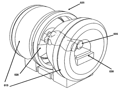
(FIG. 1 through FIG. 4). In this embodiment, the split solenoidal MRI (015)
remains
stationary while the shielded co-registered isotopic radiation source with a
multi-leaf
collimator IMRT unit (020) is rotated axially around the couch on the gantry
(025) (note
more than one (020) could be beneficially employed). The patient (035) is
positioned
on the patient couch (030) for simultaneous imaging and treatment. The co-
registered
isotopic radiation source (020) with a multi-leaf collimator contains a
radioisotopic
source (115) which is collimated with a fixed primary collimator (120), a
secondary
doubly divergent multileaf collimator (125), and tertiary multi-leaf
collimator (130) to
block interleaf leakage from the secondary multi-leaf collimator (125) (FIG. 5
through
FIG. 7).
[00028] This embodiment is beneficial as it removes the need for rotating the
open
MRI to provide axial treatment beam access and it provides a magnetic field
along the
{WP218792;4} 15
CA 02749057 2011-08-10
WO 2005/081842 PCT/US2005/004953
patient in the cranial-caudal direction, allowing for improved MRI speed using
parallel
multi-phased array RF transceiver coils for fast image acquisition.
[00029] We now describe additional beneficial embodiments of the process of
this
invention with varying complexity and computational demands. All of these
process
embodiments could employ any device embodiment. All such process embodiments
may include the step of acquiring high resolution diagnostic quality
volumetric MRI
data before the daily delivery of radiation and then acquiring real-time MRI
data during
the radiation delivery where the real-time data may be collected on a
different spatial
grid or with a diminished signal-to-noise ratio to improve the speed of
acquisition. One
beneficial process embodiment would take the MRI data and apply methods known
in
the art for deformable image registration and dose calculation to the
delivered IMRT
cobalt unit fluences to determine the dose delivered to the target and
critical structures
during each delivery fraction. Corrections to the patient's treatment could
then be taken
to add or subtract delivery fractions to improve tumor control or reduce side
effects,
respectively. Along with the dosimetric assessment, the size and progression
of the
patient's disease would also be assessed on a daily basis.
[00030] A second beneficial process embodiment would take the MRI data and
perform a reoptimization of the IMRT treatment plan before each single
radiation
delivery to improve the accuracy of the treatment delivery. This process would
be
combined with the previous process to assess the dose delivered to the target
and critical
structures during each delivery fraction.
[00031] A third beneficial process embodiment would take the MRI data and
perform a reoptimization of the IMRT treatment plan on a beam-by-beam basis
before
the delivery of each radiation beam in a single radiation delivery to improve
the
accuracy of the treatment delivery. This process generally includes that the
first process
to be performed rapidly before each beam delivery.
[00032] A fourth beneficial process embodiment would take the MRI data and
perform reoptimization of the IMRT treatment plan on a moment-by-moment basis
during the delivery of each part of each radiation beam in a single radiation
delivery to
improve the accuracy of the treatment delivery. This process includes that the
first
process to be performed in real-time substantially simultaneously with the
radiation
delivery. The present invention contemplates the use of parallel computation
{ WP218792;4} 16
CA 02749057 2011-08-10
WO 2005/081842 PCT/US2005/004953
employing many computers beneficially connected via a low latency local
network or a
secure connection on a wide area network may be used to greatly enhance the
speed of
the algorithms known in the art for MRI image reconstruction, deformable image
registration, dose computation, and IMRT optimization.
[00033] In another aspect, the present invention also provides a method of
applying
radiotherapy, having the steps of determining a treatment plan for applying
radiotherapy; obtaining images of a target region within a volume of a subject
using a
magnetic resonance imaging (MRI) system; irradiating the target and critical
structure
regions with a treatment beam, wherein the treatment beam treats the target
region; and
continuing to obtain images of the target and critical structure regions
during irradiation
of the target region; wherein the treatment plan may be altered during
treatment based
upon images of the target and critical structure regions obtained during
treatment.
{ WP218792;4} 17
CA 02749057 2011-08-10
WO 2005/081842 PCTIUS2005/004953
BRIEF DESCRIPTION OF DRAWINGS
[00034] There are shown in the drawings, embodiments which are presently
contemplated, it being understood, however, that the invention is not limited
to the
precise arrangements and instrumentalities shown.
[00035] FIG. 1 is a schematic of a radiation therapy system including an open
split
solenoidal magnetic resonance imaging device (015), a shielded co-registered
isotopic
radiation source with a multi-leaf collimator (020) (note that more than one
020 could
be applied in a beneficial embodiment), a gantry (025) for changing the angle
of (020),
a patient couch (030), and a patient (035) in position for simultaneous
imaging and
treatment.
[00036] FIG. 2 is a demonstration of gantry rotation, where the shielded co-
registered isotopic radiation source with a multi-leaf collimator (020), has
been rotated
from a right lateral beam position to an anterior-posterior beam position.
[00037] FIG. 3 is a top view of the system in FIG. 1.
[00038] FIG. 4 is a side view of the system in FIG. 1.
[00039] FIG. 5 is a detailed schematic of the co-registered isotopic radiation
source with a multi-leaf collimator shown as (020) in FIG 1. A radioisotopic
source
(115), is shown with a fixed primary collimator (120), a secondary doubly
divergent
multileaf collimator (125), and tertiary multi-leaf collimator (130) to block
interleaf
leakage from the secondary multi-leaf collimator (125).
[00040] FIG. 6 is a perspective view of the secondary doubly divergent multi-
leaf
collimator (125), and the tertiary multi-leaf collimator (130) to block
interleaf leakage
from the secondary multi-leaf collimator (125).
[00041] FIG. 7 is a beams-eye view of the radioisotopic source (115), the
secondary doubly divergent multi-leaf collimator (125), and the tertiary multi-
leaf
{ WP218792;4} 18
CA 02749057 2011-08-10
WO 2005/081842 PCTIUS2005/004953
collimator (130) to block interleaf leakage from the secondary multi-leaf
collimator
(125).
[00042] FIG. 8 displays axial dose distributions from the single head-and-neck
]MRT case planned using the commissioned cobalt beamlets.
[00043] FIG. 9 displays the DVH data derived from the single head-and-neck
IMRT case planned using the commissioned cobalt beamlets.
[00044] FIG. 10 cobalt beamlets dose distributions in water with and without a
0.3
Tesla magnetic field.
[00045] FIG. 11 cobalt beamlets dose distributions in water and lung with and
without a 0.3 Tesla magnetic field.
[00046] FIG. 12 cobalt beamlets dose distributions in water and air with and
without a 0.3 Tesla magnetic field.
DETAILED DESCRIPTION OF THE INVENTION
[00047] The present invention is more particularly described in the following
examples that are intended to be illustrative only since numerous
modifications and
variations therein will be apparent to those skilled in the art. As used in
the
specification and in the claims, the singular form "a," "an," and "the" may
include plural
referents unless the context clearly dictates otherwise. Also, as used in the
specification
and in the claims, the term "comprising" may include the embodiments
"consisting of
and "consisting essentially of."
[00048] The invention is both a device and a process for performing high
temporal-
and spatial- resolution magnetic resonance imaging (MRI) of the anatomy and
disease
of a patient during intensity modulated radiation therapy (IMRT) to directly
measure
and control the highly conformal ionizing radiation dose delivered to the
patient. In a
beneficial embodiment, this invention combines the technologies of an open MRI
that
allows for axial access with IMRT radiation beams to the patient, a multileaf-
collimator
or compensating filter-based IMRT delivery system, and cobalt-60 teletherapy
radiation
source or sources into a single co-registered and gantry mounted system.
{ WP218792;4} 19
CA 02749057 2011-08-10
WO 2005/081842 PCT/US2005/004953
[00049] As mentioned, the prior art does not simultaneously image the internal
soft
tissue anatomy of a person in real-time during the delivery of radiation
therapy while
the beams are striking the patient. Rather, an image is generated prior to
and/or after the
radiation delivery, and these images do not reflect any movement and/or
natural
changes that may occur in the patient during radiation delivery. As such,
targeted
radiation without the invention described here may not be successful if, after
taking an
initial image, the portion of the body to be treated either changes in size
naturally, or
changes in location due to the shifting of the patient prior to treatment;
i.e., the
occurrence of patient setup errors or errors in the geometry and alignment of
the
patients anatomy; physiological changes in the patient, such as weight loss or
tumor
growth and shrinkage; and organ motions in the patient including but not
limited to
breathing motion, cardiac motion, rectal distension, peristalsis, bladder
filling, and
voluntary muscular motion.
[00050] The present invention helps to eliminate all of these problems by
performing real-time MRI of the patient substantially simultaneous to
radiation
delivery, and then readjusting the targeted radiation if the region to be
treated suffers
from any type of dosimetric error caused patient setup error, physiological
change, and
inter-fraction or intra-fraction organ motion. Many actions may be taken
including, but
not limited to: shifting the patient position to account for changes in size
and/or position
of targets and anatomy; stopping treatment altogether to permit additional
calculations
to be determined before restarting treatment or allow for the cessation of
transitory
motion; adding extra delivery fractions to increase the probability of tumor
control or
limiting the number of delivery fractions to decrease the probability of side
effect; any
of the beneficial process embodiments previous described; and reoptimizing the
IMRT
treatment plan on a variety of time scales, e.g., reoptimization for every
delivery, every
beam, or every segment in the IMRT plan is performed..
[00051] A beneficial embodiment of the present invention includes a computer
controlled cone-beam cobalt therapy unit, such as a cobalt-60 therapy unit,
equipped
with a multileaf collimator or an automated compensating filter system mounted
on a
rotational gantry along with an orthogonally mounted "Open" MRI unit. As seen
in
FIG. 1, the IMRT cobalt unit (020) projects its cone-beam geometry radiation
down the
center of the opening of the axial open MRI unit (015) and the IMRT cobalt
unit rotates
{ WP218792;4} 20
CA 02749057 2011-08-10
WO 2005/081842 PCTIUS2005/004953
axially (about the longitudinal (cranial-caudal) axis of the patient) about
the patient on a
gantry (025). An adjustable treatment couch (030) may be used to support the
patient in
a stationary position while the gantry rotates to change the beam angle.
[00052] The present invention uses cobalt teletherapy as the radiation
therapy.
While some IMRT uses a linear electron accelerator for delivering a more
penetrating
radiation therapy, the accelerator itself produces a treatment beam that is
highly variable
in regards to the level of radiation emitted. As such, it becomes difficult to
accurately
determine the amount of radiation that is being used on the patient and to
coordinate the
motion of an MLC for IMRT delivery. Gamma-rays are electromagnetic radiation
emitted by the disintegration of a radioactive isotope and have enough energy
to
produce ionization in matter, typically from about 100 keV to well over 1 MeV.
The
most useful gamma-emitting radioactive isotopes for radiological purposes are
found to
be cobalt (Co 60), iridium (Ir 192), cesium (Cs 137), ytterbium (Yb 169), and
thulium
(Tm 170). As such, the disintegration of a radioactive isotope is a well-known
phenomena and, therefore, the radiation emitted by cobalt teletherapy is more
consistent
and, therefore, easier to calculate in terms of preparing a treatment regimen
for a
patient.
[00053] Enablement of the present invention's cobalt IMRT has been
demonstrated
via computational analysis. Simulations have been performed of IMRT delivery
with a
commercially available cobalt therapy unit and a MLC. A 3D image-based
radiation
therapy treatment planning system with a cobalt beamlet model was commissioned
and
validated using measured radiochromic film data from a Theratronics 1000C
cobalt
therapy unit. An isotropic 4x4x4 mm3 dose voxel grid (effectively Shannon-
Nyquist
limited for r-ray IMRT source penumbra) was generated. This bean-let model was
fitted to published data and validated with radiochromic film measurements of
1 x 1 cm2
beamlets formed by a Cerrobend block and measured using a previously reported
methodology. The calculation depths were then determined for the same voxels
with
standard three-dimensional ray-tracing of the structures. Density scaling to
the depths
computed was used to better account for tissue heterogeneities in the dose
model. The
CPLEX, ILOG Concert Technologies industrial optimization solver using an
implementation of the barrier interior-point method with dense column handling
for
IMRT optimization was used to solve for optimal IMRT plans. Beanilet fluences
were
{WP218792;4} 21
CA 02749057 2011-08-10
WO 2005/081842 PCTIUS2005/004953
discretized for each beam angle to 5% levels for leaf sequencing. The
resulting plan
dose distribution and histograms were computed by summing the dose values
weighted
by the deliverable discretized intensities. Leaf-transmission leakage
intensities were
conservatively estimated at 1.7% for otherwise zero intensity beamlets.
Finally,
standard methods of heuristic leaf-sequencing optimization to create delivery
instructions for the treatment plans were employed. We adopted the Virginia
Medical
College simultaneous integrated boost (SIB) target dose-level scheme as it is
the largest
maximum to minimum clinical prescription dose ratio advocated in the
literature,
making it the most difficult dose prescription scheme to satisfy. Head-and-
neck IMRT
provides an excellent basis for testing IMRT optimization for several reasons:
1) there
are well defined treatment goals of sparing salivary glands and other
structures while
maintaining homogeneous target coverage; 2) attempting to achieve these goals
tests
IMRT optimization to its technical limits; and 3) a large phase VII multi-
institutional
trial, the Radiation Therapy Oncology Group (RTOG)'s H-0022 Phase I/II Study
of
Conformal and Intensity Modulated Irradiation for Oropharyngeal Cancer, has
defined
a common set of planning criteria. The case examined was run with 7 equispaced
beams having International Electrotechnical Commission (EEC) gantry angles of
0 ,
51 , 103 , 154 , 206 , 257 , and 309 . The treatment planning system generated
1,289
beamlets to adequately cover the targets from the seven beam angles, and the
4mm
isotropic voxel grid generated 417,560 voxels. Results are shown in FIG 8 and
FIG 9.
Note that our system normalized plans to ensure 95% coverage of the high dose
target.
FIG 8 displays axial dose distributions from the single head-and-neck EMRT
case
planned using the commissioned cobalt beamlets. Excellent target coverage and
tissue
sparing may be observed. FIG 9 displays the DVH data derived from the leaf
sequenced and leakage corrected plan (i.e., deliverable plan) using the 4 mm
voxels and
1 Gy dose bins. The cobalt source based IMRT created an excellent IMRT
treatment
plan for a head-and-neck patient. The 7-ray IMRT was able to clearly spare the
right
parotid gland (RPG) and keep the left parotid (LPG) and right submandibular
glands
(RSMG) under 50% volume at 30 Gy, while covering more than 95% of the target
volumes (CTV and GTV) with the prescription dose or higher. All other
structures
were below tolerance. The unspecified tissue (SKIN) was kept below 60 Gy, with
less
than 3% of the volume above 50 Gy. The optimization model used was the same as
{WP218792;4) 22
CA 02749057 2011-08-10
WO 2005/081842 PCTIUS2005/004953
published in Romeijn et al. and was not modified for the cobalt beams. For
sites with
larger depths such as prostate and lung it is known in the art that the
addition of extra
beams or isocenters allows for the creation of treatment plans using cobalt
IMRT that
may achieve the same clinical quality criteria as linac-based IMRT. This
enabling
demonstration shows that a cobalt therapy unit is capable of providing high
quality
IMRT.
Enablement of the present invention's dose computation for cobalt IMRT in the
presence of the magnetic field has been demonstrated via computational
analysis. In
addition, by using cobalt teletherapy, the present invention is better able to
make
calculations based upon the magnetic field of the MRI. When the radiation
therapy is
performed while the patient is stationed within the MRI, the magnetic field
will cause a
slight deflection of the targeted radiation. As such, the calculations used to
determine
the treatment regimen need to take this deflection into account. A charged
particle
moving in a vacuum at a velocity, v, in the presence of a magnetic field, B,
experiences a Lorentz force given by F = q(v x f?). This force is not
significant enough
to significantly change the physics of the interactions of ionizing photons
and electrons
with matter; however, it may influence the overall transport of ionizing
electrons and
hence the resulting dose distribution. The impact of magnetic fields on the
transport of
secondary electrons has been well studied in the physics literature, starting
more than 50
years ago. Recent studies have employed Monte Carlo simulation and analytic
analysis
in an attempt to use a localized magnetic field to help focus or trap primary
or
secondary electrons to increase the local dose deposition in the patient. All
of these
studies have examined aligning the direction of the magnetic field lines along
the
direction of the beam axis to laterally confine the electron transport with
the Lorentz
force (called "longitudinal" magnetic fields, where the term longitudinal
refers to the
beam and not the patient). For high field MRI, with magnetic fields between
about 1.5-
3.0 T is known that the initial radius of gyration is small with respect to
the MFP of
large-angle scattering interactions for the secondary electrons
(bremsstrahlung, elastic
scatter, and hard collisions) and this condition results in the desired
trapping or focusing
of the electrons. As the electrons lose energy the radius decreases as it is
proportional
to Ivl and, in the absence of large-angle scattering interactions (CSDA) the
electrons
{ WP218792;4} 23
CA 02749057 2011-08-10
WO 2005/081842 PCT/US2005/004953
would follow a spiral with decreasing radius until they stop. Although this
spiraling
may change the fluence of electrons it is known that it does not produce any
significant
synchrotron radiation. In the present invention, the magnetic field must be
orthogonal
to the radiation beams in order allow parallel MRI for real-time imaging.
Recent work
has shown that a 1.5 T magnetic field perpendicular to the beam axis of a 6MV
linac
beam may significantly perturb the dose distribution to water for a 6 MV linac
beamlet.
Both to avoid such dose distribution distortions and to prevent MRI artifacts
that could
compromise the spatial integrity of the imaging data, a beneficial embodiment
of the
present invention uses a low field open MRI design that allows the magnetic
field to be
directed along the superior-inferior direction of the patient (see FIG. 1).
Simple
estimates of the radii of gyration for secondary electrons from cobalt y rays
indicate that
the radii of gyration are much greater than the MFP for large-angle scattering
interactions for electrons. This is easily understood as the Lorentz force is
proportional
to the magnitude of the magnetic field, 01, and
the radius of gyration is inversely
proportional to the magnetic field (104). We have pursued modeling a beamlet
from a
cobalt y-ray source in a slab phantom geometry using the well-validated
Integrated
Tiger Series (ITS) Monte Carlo package and its ACCEPTM subroutine for
transport in
magnetic fields. For the simulations we employed 0.1 MeV electron and 0.01 MeV
photon transport energy cutoffs, the standard condensed history energy grid
(ETRAN
approach), energy straggling sampled from Landau distributions, mass-
collisional
stopping powers based on Bethe theory, default electron transport substep
sizes, and
incoherent scattering including binding effect. Three pairs of simulations
were run
where each pair included the run with and without a 0.3 T uniform magnetic
field
parallel to the beam direction. A 2 cm circular cobalt y-ray beamlet was
modeled on the
following geometries: a 30x30x30 cm3 water phantom; a 30x30x30 cm3 water
phantom
with a 10 cm lung density (0.2 g/cc) water slab at 5 cm depth; and a 30x30x30
cm3
water phantom with a 10 cm air density (0.002 g/cc) water slab at 5 cm depth.
Simula-
tions were run with between 30 and 100 million histories on a P4 1.7 GHz PC
for
between 8 and 30 hours to obtain less than a percent standard deviation in the
estimated
doses. The results are displayed in Figures 10-12. FIG. 10 clearly
demonstrates that a
0.3 T perpendicular uniform magnetic field, as would exist in a beneficial
embodiment
of the current invention will not measurably perturb the dose distribution in
soft tissue
{WP218792;4) 24
CA 02749057 2011-08-10
WO 2005/081842 PCTIUS2005/004953
or bone. A very useful treatment site for the present invention will be lung
and thorax
which contains the most significant tissue heterogeneities in the body. As
seen in FIG.
11, adding a 12 cm lung density (0.2 g/cc) water slab to the phantom causes a
very
small yet detectable perturbation in the dose at the interfaces of the high
and low density
regions. These perturbations are small enough to allow acceptable clinical
application
without correction. In FIG. 12, we finally observe significant perturbations,
which exist
largely in the low-density and interface regions. This demonstrates that air
cavities will
hold the greatest challenge for accurate dosimetry. However, other than at
interfaces
with lower density media there should be no significant perturbations in soft
tissue and
bone (where the MFP shortens even more than soft tissue). This data
demonstrates that
in a beneficial embodiment of the present invention with a low (.2-.5 Tesla)
field MRI,
dose perturbation will be small except inside of air cavities were accurate
dosimetry is
not required due to an absence of tissue. By using a known radiation source,
such as a
cobalt teletherapy unit, the amount of deflection may be easily determined if
the
strength of the MRI field is known. However, even if the strength of the field
is known,
if a linear accelerator is used, the unknown energy spectrum of the radiation
makes the
calculations much more difficult.
[00054] Alternate sources of radiation that do not interfere significantly
with the
operations of the MRI unit such as protons, heavy ions, and neutrons that are
produced
by an accelerator or reactor away from the MRI unit and transported by beam to
patient
are also included in the invention.
[00055] In addition, the strength of the MRI field will factor into the
calculations
and, as a result, the use of open MRIs offers advantages over closed MRIs. In
an open
MRI, the strength of the field generated is generally less than the field of a
closed MRI.
As such, the images resulting from an open MRI have more noise and are not as
clear
and/or defined as images from a higher field closed MRI. However, the stronger
field
of the closed MRI causes more of a deflection of the radiation treatment than
the weaker
field of an open MRI. Accordingly, depending on the characteristics most
beneficial to
a given treatment regimen, the present invention contemplates that a closed
MRI could
be used. However, due to ease of calculation and/or the fact that a slightly
less clear
image during treatment is sufficient for adjusting most treatment regimens,
the present
invention contemplates that an open MRI of the geometry shown in FIG. 1, is
used with
{ WP218792;4} 25
CA 02749057 2011-08-10
WO 2005/081842 PCT/US2005/004953
the cobalt teletherapy to eliminate significant dose perturbations, prevent
spatial
imaging distortions, and allow for fast parallel phased array MRL
[00056] By using an open MRI and cobalt teletherapy, the present invention
provides three dimensional (3D) imaging of a patient during the radiation
therapy. As
such, by using the 3D images of the target region and the planning images of
the target
region a displacement is determined which is updated based upon the continuous
3D
images received during the radiotherapy process. Using the information
obtained, the
patient may then be then translated relative to the treatment beam to reduce
the
displacement during the irradiation process, such as if the measured
displacement is
outside a predetermined limit. Irradiation may then continue after
translation.
Alternatively, the treatment beam may be moved. The translation may occur
during
treatment or treatment may be stopped and then translation may occur.
[00057] By using 3D images during treatment and using these images to rapidly
position and/or adjust the patient during the radiotherapy process, treatment
accuracy
maybe substantially improved. If the patient becomes misaligned while
radiation is
being applied, the misalignment may be mitigated through positional
adjustment. In
addition to possible dose escalation, improved positional accuracy permits
treatment of
tumors that are currently considered not treatable with radiation using
conventional
systems. For example, primary spinal cord tumors and spinal cord metastases
are
typically not treated by conventional radiation systems due to the high
accuracy needed
to treat lesions in such important functional anatomic regions. The increased
precision
provided by 3D imaging during treatment makes it feasible to treat these types
of
tumors. Improvements are also expected for targets located in the lung, upper
thorax,
and other regions where intra-fraction organ motions are known to cause
problems with
radiotherapy dosimetry.
[00058] In an alternative embodiment, the present invention may include a
separate
guidance system to track the patient location that may be used to correlate
the actual
patient position with the imaging information obtained during both planning
and
radiotherapy. This portion of the invention may significantly improve the ease
of
patient positioning by providing updateable image correlation and positioning
information throughout the patient set-up and treatment delivery phases, even
when the
patient is moved to positions that are not perpendicular to the coordinate
system of the
(WP218792;4) 26
CA 02749057 2011-08-10
WO 2005/081842 PCT/US2005/004953
therapy machine. This ability to monitor patient position at non-coplanar
treatment
positions may be a significant improvement over conventional radiotherapy
systems. In
one beneficial embodiment, the guidance system may include an adjustable bed
or
couch for the patient to be placed upon. In an alternative beneficial
embodiment, the
guidance system may include a gantry that permits substantially simultaneous
movement of the MRI and the cobalt therapy unit. Some beneficial embodiments
include both the gantry and the adjustable bed or couch.
[00059] The present invention determines the initial radiation treatment
and/or any
changes to the treatment regimen based upon the use of a computer program that
takes
into account various factors including, but not limited to, the area of the
patient to be
treated, the strength of the radiation, the strength of the MRI field, the
position of the
patient relative to the radiation unit, any change in the patient during
treatment, and/or
any positional changes necessary of the patient and/or the radiation unit
during
treatment. The resulting ] RT is then programmed and the treatment is started.
[00060] One embodiment for determining a treatment plan for intensity
modulated
radiation treatment (IMRT) as used in the present invention includes the steps
of
dividing a three dimensional volume of a patient into a grid of dose voxels,
wherein
each dose voxel is to receive a prescribed dose of radiation from a plurality
of beamlets
each having a beamlet intensity; and providing a convex programming model with
a
convex objective function to optimize radiation delivery. The model is solved
to obtain
a globally optimal fluence map, the fluence map including beamlet intensities
for each
of the plurality of beamlets. This method is described in greater detail in
related
application U.F. Disclosure No. 11296.
[00061] In general, the method used for determining a treatment plan, in one
beneficial embodiment, is the interior point method and variants thereof. This
method
is beneficial due to its high efficiency and resulting generally short
computational times.
The interior point method is described in a book by Steven J. Wright entitled
"Primal-
Dual Interior-Point Methods" (SIAM Publications, 1997, ISBN 089871382X).
Primal-
dual algorithms have emerged as the most beneficial and useful algorithms from
the
interior-point class. Wright discloses the major primal-dual algorithms for
linear
programming, including path-following algorithms (short- and long-step,
predictor-
corrector), potential-reduction algorithms, and infeasible-interior-point
algorithms.
{WP218792;4} 27
CA 02749057 2011-08-10
WO 2005/081842 PCT/US2005/004953
[00062] Once the treatment plan is determined, the present invention enables
the
clinician to ensure that the treatment plan is followed. The patient to be
treated is
placed in the MRI. An image of the area to be treated is taken and the MRI
continues to
transmit a 3D image of the area. The treatment plan is input into the cobalt
radiation
teletherapy unit and treatment commences. During treatment, a continuous image
of the
area being treated is observed. If the location of the area to be treated
changes, such as
if the patient moves or the area to be treated changes in size, the present
invention either
recalculates the treatment plan and/or adjusts the patient or radiation unit
without
interrupting treatment; or the present invention stops treatment, recalculates
the
treatment plan, adjusts the patient and/or adjusts the radiation unit before
recommencing
treatment.
[00063] The present invention contemplates multiple process embodiments that
may be used in improving the accuracy of the patient's therapy. One process
embodiment would take the MRI data and apply methods known in the art for
deformable image registration and dose calculation to the delivered IMRT
cobalt unit
fluences to determine the dose delivered to the target and critical structures
during each
delivery fraction. Corrections to the patient's treatment could then be taken
to add or
subtract delivery fractions to improve tumor control or reduce side effects,
respectively.
Along with the dosimetric assessment, the size and progression of the
patient's disease
would also be assessed on a daily basis.
[00064] A second process embodiment would take the MRI data and perform a
reoptimization of the IMRT treatment plan before each single radiation
delivery to
improve the accuracy of the treatment delivery. This process would be combined
with
the previous process to assess the dose delivered to the target and critical
structures
during each delivery fraction.
[00065] A third process embodiment would take the MRI data and perform a
reoptimization of the IMRT treatment plan on a beam-by-beam basis before the
delivery
of each radiation beam in a single radiation delivery to improve the accuracy
of the
treatment delivery. This process includes that the first process be performed
rapidly
before each beam delivery.
[00066] A fourth process embodiment would take the MRI data and perform
reoptimization of the IMRT treatment plan on a moment-by-moment basis during
the
{ WP218792;4} 28
CA 02749057 2011-08-10
WO 2005/081842 PCT/US2005/004953
delivery of each part of each radiation beam in a single radiation delivery to
improve the
accuracy of the treatment delivery. This process also includes that the first
process be
performed in real-time simultaneously with the radiation delivery. The present
invention contemplates the use of parallel computation employing many
computers
beneficially connected via a low latency local network or a secure connection
on a wide
area network may be used to greatly enhance the speed of the algorithms known
in the
art for MRI image reconstruction, deformable image registration, dose
computation, and
IMRT optimization.
[00067] Reference is now made with specific detail to the drawings in which
like
reference numerals designate like or equivalent elements throughout the
several views,
and initially to Figure 1.
[00068] In FIG. 1, the present invention, in one embodiment, shows the system
of
the present invention and having an open MRI 015 and an IMRT cobalt therapy
unit
020. The system also includes a means to perform IMRT in 020, such as an MLC
or
compensation filter unit, and a gantry 025 that may be used for cobalt unit
020 rotation
while keeping the MRI 015 stationary. The patient 035 is positioned in the
system on
an adjustable, stationary couch 030.
[00069] FIG. 2 shows the system in use and wherein the gantry 025 has been
rotated approximately 90 degrees clockwise. As such, the cobalt therapy unit
020 is in
position to treat the patient 035 in one of many selected locations. FIG. 3 is
a top view
of the system in FIG. 1. FIG. 4 is a side view of the system in FIG. 1.
[00070] Although the illustrative embodiments of the present disclosure have
been
described herein with reference to the accompanying drawings and examples, it
is to be
understood that the disclosure is not limited to those precise embodiments,
and various
other changes and modifications may be affected therein by one skilled in the
art
without departing from the scope of spirit of the disclosure. All such changes
and
modifications are intended to be included within the scope of the disclosure
as defined
by the appended claims.
(WP218792;4) 29