Note: Descriptions are shown in the official language in which they were submitted.
CA 02749433 2011-08-09
TITLE OF THE INVENTION:
ADJUSTABLE SUPPORT BRACKET FOR A HEADER TRANSPORT WAGON
BACKGROUND OF THE INVENTION
Field of the Invention
[0001] The present invention relates generally to a support bracket for a
transport wagon used to transport large objects, such as combine headers and
other
farm equipment
Description of the Related Art
[0002] Transport wagons for transporting large farm equipment, such as a
cutting header (grain platform, draper, or corn platform) of a combine
harvesting
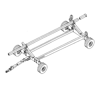
machine, are known. Figure 1 illustrates a conventional transport wagon.
[0003] A cutting header is the front mechanism of a combine harvesting
machine that cuts the crop and feeds it to the harvesting machine for
threshing. The
cutting header is wider than the body of the harvesting machine and thus, it
is
difficult and unsafe to transport the entire harvesting machine. Due to its
large size,
the cutting header is removed from the combine harvesting machine and
transported
sideways on a transport wagon for safe road travel.
[0004] Generally support brackets are mounted on the frame of the transport
wagon as a the mating structure between the transport wagon and the header,
and
support a portion of one end of the header.
[0005] U.S. Patent Nos. 5,333,904; 5,785,472; and 6,272,824 each disclose
known support brackets for transport wagons, which are secured to the frame
with a
variation of a bolt. For Instance, U.S. Patent No. 5,333,904 discloses a clamp
that
includes a nut and bolt that pulls two plates, one on each side of the frame,
together,
1589632_1
thereby clamping the support bracket to the frame. U.S. Patent Nos. 5,785,472
and
6,272,824 disclose a bolt and a cam handle to clamp the support bracket to the
frame in a similar manner. However, these designs are disadvantageous because
bolt threads can get damaged and separate tools are required to remove and
replace the bolt in order to adjust the support bracket height or re-position
it along
the frame. Another disadvantage is that the process of removing a threaded
member (e.g. a bolt) and components is slow and time-consuming.
[0006] Other support brackets utilize various configurations to support
different types of headers, e.g., headers with lower edges having different
geometric
configurations, corn headers, or grain platforms. For instance, the bracket
disclosed
by U.S. Patent Nos. 5,333,904 and 5,785,472 require additional support
member(s),
and the bracket of U.S. Patent No. 6,272,824 requires additional rest pad(s).
These
designs are disadvantageous because these secondary structures add extra,
burdensome weight to the support bracket, making adjustments along the frame
more difficult. A further disadvantage is that the secondary structures must
be
separately stored when not in use and thus are easily lost or misplaced.
[0007] Thus, there is a need for new and improved support brackets that
do
not suffer from the limitations of the prior art.
SUMMARY OF THE INVENTION
[0008] According to the present invention, an adjustable support bracket
is
provided for a transport wagon, used to hold and transport a large object with
improvements over the prior art.
f0008a1 According to the present invention, there is provided an
adjustable
support bracket for a transport wagon used to hold and transport a large
object, said
2
CA 2749433 2017-11-20
transport wagon having a frame with a top surface, opposed side surfaces and a
bottom surface, said adjustable support bracket comprising:
an angled adjustable seat for supporting a portion of a large object, said
angled adjustable seat having a top surface comprising a inclined plate and
leg
members comprising a rear plate and a front portion, wherein, the leg members
are
connected to a first plate, wherein, the angled adjustable seat further
comprises at
least one side plate connected by a hinge mechanism to permit said at least
one
side plate to be adjusted to a pocket position or a lower position; and
a tool-free coupling for removably coupling the adjustable support bracket
with
the frame of the transport wagon without tools, such that the angled
adjustable seat
is secured onto the top surface to the frame of the transport wagon and the
rear
plate and the front portion of the angled adjustable seat are clamped to the
side
surfaces of the frame of the transport wagon;
wherein the angled adjustable seat further comprises a pin to secure said side
plate
or side plates in the pocket position.
10008b1 According to the present invention, there is provided an
adjustable
support bracket for a transport wagon used to hold and transport a large
object, said
transport wagon having a frame with a top surface, opposed side surfaces and a
bottom surface, said adjustable support bracket comprising:
an angled adjustable seat for supporting a portion of a large object, said
angled adjustable seat having a top surface comprising a inclined plate and
leg
members comprising a rear plate and a front portion, wherein, the leg members
are
connected to a first plate, wherein, the angled adjustable seat further
comprises at
least one side plate connected by a hinge mechanism to permit said at least
one
side plate to be adjusted to a pocket position or a lower position; and
2a
CA 2749433 2017-11-20
a tool-free coupling for removably coupling the adjustable support bracket
with
the frame of the transport wagon without tools, such that the angled
adjustable seat
is secured onto the top surface to the frame of the transport wagon and the
rear
plate and the front portion of the angled adjustable seat are clamped to the
side
surfaces of the frame of the transport wagon,
wherein the tool-free coupling includes a winch, a flexible member, and winch
bar.
100080 According to the present invention, there is provided an
adjustable
support bracket for a transport wagon used to hold and transport a large
object, said
transport wagon having a frame with a top surface, opposed side surfaces and a
bottom surface, said adjustable support bracket comprising:
an angled adjustable seat for supporting a portion of a large object, said
angled adjustable seat having a top surface comprising a inclined plate and
leg
members comprising a rear plate and a front portion, wherein, the leg members
are
connected to a first plate, wherein, the angled adjustable seat further
comprises at
least one side plate connected by a hinge mechanism to permit said at least
one
side plate to be adjusted to a pocket position or a lower position;
a tool-free coupling for removably coupling the adjustable support bracket
with
the frame of the transport wagon without tools, such that the angled
adjustable seat
is secured onto the top surface to the frame of the transport wagon and the
rear
plate and the front portion of the angled adjustable seat are clamped to the
side
surfaces of the frame of the transport wagon; and
height-adjust pins.
Preferred embodiments of the invention are described hereunder.
[0009] The conventional transport wagon has a frame with a top surface,
opposed side surfaces and a bottom surface. According to an embodiment of the
present invention, an adjustable support bracket has an angled adjustable seat
for
2b
CA 2749433 2017-11-20
CA 02749433 2011-08-09
Attorney Docket: 1994-340
supporting a portion of a large object The angled adjustable seat has a top
surface
and leg members. The top surface includes an inclined plate. The leg members
include a rear plate and a front portion. The leg members are connected to a
first
plate. The angled adjustable seat has at least one side plate connected by a
hinge
mechanism to permit at least one side plate to be adjusted to a pocket
position or a
lower position. Means for removably coupling the adjustable support bracket
with
the frame of the transport wagon without tools is provided, such that the
angled
adjustable seat can be secured onto the top surface to the frame of the
transport
wagon and the rear plate and the front portion of the angled adjustable seat
can be
clamped to the side surfaces of the frame of the transport wagon.
[0010] According to another embodiment of the present invention, the
adjustable support bracket has an angled adjustable seat that has a pin to
secure a
side plate in a pocket position.
[0011] According to another embodiment of the present invention, the
adjustable support bracket has an inclined plate adapted to receive a side
plate.
[0012] According to another embodiment of the present invention, the
adjustable support bracket has a side plate adapted to receive a pin that
secures the
side plate in a pocket position.
[0013] According to another embodiment of the present invention, the
adjustable support bracket has a leg member with a panel and two side panels.
[0014] According to another embodiment of the present invention, the
adjustable support bracket has a leg member with a panel and two side panels,
and
the side panels are adapted to receive a pin that secures the side plate in a
pocket
position.
3
CA 02749433 2011-08-09
Attorney Docket: 1994-340
[0015] According to another embodiment of the present invention, the
adjustable support bracket has a winch, flexible member, and winch bar for
removably coupling the adjustable support bracket with the frame of the
transport
wagon without separate tools.
(0016] According to another embodiment of the present invention, the
adjustable support bracket has a winch, strap, and winch bar for removably
coupling
the adjustable support bracket with the frame of the transport wagon without
separate tools.
(0017] According to another embodiment of the present invention, the
adjustable support bracket has a winch, wire, and winch bar for removably
coupling
the adjustable support bracket with the frame of the transport wagon without
separate tools.
[0018] According to another embodiment of the present invention, the
adjustable support bracket has a winch, cable, and winch bar for removably
coupling
the adjustable support bracket with the frame of the transport wagon without
separate tools.
[0019] According to another embodiment of the present invention, the
adjustable support bracket has leg members adapted to receive the flexible
member.
[0020] According to another embodiment of the present invention, the
adjustable support bracket has a hinge mechanism comprised of a bar.
[0021] According to another embodiment of the present invention, the
adjustable support bracket has a flexible member attached to a hook that can
be
engaged with the hinge mechanism.
[0022] According to another embodiment of the present invention, the
adjustable support bracket has height-adjust pins.
4
CA 02749433 2011-08-09
Attorney Docket: 1994-340
[0023] According to another embodiment of the present invention, the
adjustable support bracket has a rear plate and front panel adapated to
receive the
height-adjust pins.
[0024] According to another embodiment of the present invention, the
adjustable support bracket has a side plate or side plates secured to the
hinge
mechanism by a fastener.
[0025] According to another embodiment of the present invention, the
adjustable support bracket has a side plate or side plates secured to the
hinge
mechanism by a spring washer.
[0026] Further applications and advantages of various embodiments of the
present invention are discussed below with reference to the drawing figures,
BRIEF DESCRIPTION OF THE DRAWINGS
[0027] The accompanying drawings, which are incorporated herein and form
part of the specification, illustrate various embodiments of the present
invention and,
together with the description, further serve to explain the principles of the
invention
and to enable a person skilled in the pertinent art to make and use the
invention. In
the drawings, like reference numbers indicate identical or functionally
similar
elements.
[0028] Figure 1 is a perspective view of a conventional transport wagon.
[0029] Figure 2 is a perspective view of a transport wagon having two
adjustable support brackets secured to the frame of the transport wagon
according
to an embodiment the present invention.
[0030] Figure 3 is a perspective view, from the left and rear, of an
adjustable
support bracket according to an embodiment of the present invention.
CA 02749433 2011-08-09
Attorney Docket: 1994-340
[0031] Figure 4 is a perspective view, from the right and rear, of an
adjustable
support bracket according to an embodiment of the present invention.
[0032] Figure 5 is a side view of an adjustable support bracket according
to
an embodiment of the present invention.
[0033] Figure 6 is a front view of an adjustable support bracket according
to
an embodiment of the present invention.
DETAILED DESCRIPTION OF THE PREFERRED EMBODIMENTS
[0034] While the present invention may be embodied in many different forms,
a number of illustrative embodiments are described herein with the
understanding
that the present disclosure is to be considered as providing examples of the
principles of the invention and such examples are not intended to limit the
invention
to preferred embodiments described herein and/or illustrated herein.
[0035] Figure 2 depicts two adjustable support brackets (100), according to
one embodiment, secured to one arm of the frame (12) of the transport wagon
(10).
The transport wagon (10) is typically used to transport different types of
equipment
(not shown) and can be towed by a motor vehicle (e.g., truck, tractor, etc.)
with a
tongue (14). As shown, the transport wagon (10) includes a main frame (12)
coupled with caster wheels (15) and a rail (16) coupled with the frame (12)
and
supported by angled bars (18) that are adjustably connected to opposite sides
of the
frame (12). The rail can support a portion of the farm equipment and positions
the
farm equipment at an angle downwardly towards the adjustable support brackets
(100). The adjustable support brackets (100) secured to the main frame (12)
can
receive and support a portion of the lower end of the farm equipment.
[0036] Figure 3 is an angled view, from the left and rear, of an adjustable
support bracket (100) according to an embodiment of the present invention. As
6
CA 02749433 2011-08-09
Attorney Docket: 1994-340
shown, the adjustable support bracket (100) may include an angled adjustable
seat
(102) for supporting a portion of a large object (not shown) to be secured
thereto,
and a mounting portion (112). The adjustable support bracket (100) can be
removably coupled with the frame of the transport wagon without separate tools
and
adjustably positioned along the frame of the transport wagon. The angled
adjustable
seat (102) and the mounting portion (112) can be welded together to form a
shape
based on the frame of the transport wagon. The angled adjustable seat (102)
may
be one piece or comprised of a first plate (104), an inclined plate (105), and
a third
plate (106) welded together. The angled adjustable seat (102) includes one or
more
side plates (108), connected by a hinge mechanism (142). The side plates (108)
can be formed of various shapes, e.g., a side plate can be curved to provide a
specific contour (107) to better receive the object to be transported. The
mounting
portion (112) may include a number of plates. For example, the mounting
portion
may include two leg members (113, 114) welded to the angled adjustable seat
(102),
wherein one leg member is a rear plate (113) and a second leg member is a
front
portion (114) comprised of a front plate (134) and two side plates (130)
welded to
opposite ends of the front plate (134). The figures show two side plates
(108), but
the invention is intended to have one or more side plates.
[0037] Figure 4 is an angled view, from the right and rear, of an
adjustable
support bracket (100) according to an embodiment of the present invention. The
adjustable support bracket (100) may include a hinge mechanism (142) that can
include small flanges (150) connected to the first plate (104) and the rear
plate (113)
of the angled adjustable seat. The hinge mechanism (142) can further include a
shaft (144) that is engaged with the small flanges (150), e.g., a shaft (144)
fitted
through openings in the small flanges (150). The side plates (108) are engaged
with
7
CA 02749433 2011-08-09
Attorney Docket: 1994-340
the shaft (144), e.g., a shaft (144) fitted through openings in the side
panels (108).
A fastener (148) (e.g., nut and washer) can be provided to secure the side
plate
(108) to the shaft (144) and the outermost small flanges (150). Belleville
spring
washers (148) are preferred fasteners that eliminate rattling of the
components
during travel.
[0038] The side plate (108) can be rotated about the shaft (144) to an
upper
position (i.e. the left side plate (108) shown in Figure 4) or a lower
position (i.e. the
right side plate (108) shown in Figure 4). When one or more side plates (108)
are in
the upper position, the first plate (104) of the angled adjustable seat has a
pocket
configuration. The inclined plate (105) is adapted to receive a side plate
(108) in the
upper position. For instance, as shown in Figure 4, the inclined plate (105)
has
corresponding slots (126) adapted to receive the side plates (108). When all
side
plates (108) are in the lower position, the first plate (104) of the angled
adjustable
seat has an L-shaped configuration. Accordingly, the first plate (104) of the
angled
adjustable seat can be set to various configurations simply by adjusting one
or more
side plates (108). There is no need for additional support members or rest
pads for
each desired configuration, although they are optional features to one skilled
in the
art. Compared to secondary support members or rest brackets, side plates cost
less
and reduce the manufacturing costs of the adjustable support bracket. The side
plates can have universal or symmetrical designs. Moreover, side plates weigh
less
and improve the efficiency of the adjustable support bracket (100) by making
it less
burdensome to lift and move the angled adjustable seat.
[0039] Figure 5 is a side view of an adjustable support bracket (100)
according to an embodiment of the present invention. As shown, a pin (116) can
be
used as a securing means to secure a side plate (108) in the upper position.
As
8
CA 02749433 2011-08-09
Attorney Docket: 1994-340
shown, the side plates (130) of the front portion (114) of the angled
adjustable seat
can be adapted to receive the pin (116), e.g. with an opening (132) such that
the pin
runs behind the inclined plate (105). The side plate (108) can be provided
with a
hole (128) that can receive the pin (116) and which is aligned with the
opening (132)
in the side plates (130) when placed in the upper position.
[0040] Figure 6 is a front view of an adjustable support bracket (100)
according to an embodiment of the present invention. The adjustable support
bracket (100) can include means for removably coupling, without tools, the
adjustable support bracket (100) with the frame of the transport wagon.
[0041] For example, a winch (120) with a flexible strap (122) and winch bar
(118) can be provided in one embodiment. The winch (120) is connected to the
front
plate (134) of the front portion (114) of the angled adjustable seat. As shown
in
Figures 4 and 5, one end of the flexible strap (122) can be attached to a
fastener
(e.g. a hook) (146) that can be secured to the shaft (144) of the hinge
mechanism
(142). When the angled adjustable seat is placed on the frame of the transport
wagon, the free end of the flexible strap (122) can be extended through the
rear
plate (113) of the angled adjustable seat, under the wagon frame (not shown),
through the front plate (134) of the front portion (114) of the angled
adjustable seat
(as shown in Figures 3-6) and fished through the spool of the winch (120) (as
shown
in Figure 6). The winch bar (118) can be used to tighten the winch (120),
thereby
pulling down the angled adjustable seat onto the top surface of the frame and
clamping the rear plate (113) and the front portion (114) of the angled
adjustable
seat to the side surfaces of the frame of the transport wagon.
[0042] The angled adjustable seat can be adjusted vertically on the frame
or
moved horizontally along the frame by releasing the winch (120), pulling the
flexible
9
CA 02749433 2011-08-09
Attorney Docket: 1994-340
strap (122) out of the spool of the winch (120) and making the desired
adjustment.
The angled adjustable seat can be adjusted vertically by lifting the angled
adjustable
seat and inserting the two height-adjust pins (124) through the corresponding
holes
(125) in the rear plate (113) and the front plate (134). (The holes (125) are
shown in
Figure 3.) The angled adjustable seat can be adjusted horizontally along the
frame
by lifting the angled adjustable seat and moving it to the desired position
along the
frame. Once the desired adjustment has been made, the angled adjustable seat
can
be secured to the frame by fishing the flexible strap (122) through the spool
of the
winch (120) and tightening the winch (120).
[0043] The winch (120) shown in Figure 5 is an example of means for
removably coupling the adjustable support bracket (100) with the frame of the
transport wagon without tools, but the invention is not intended to be limited
to a
winch. One key feature of the means for removably coupling the adjustable
support
bracket (100) with the frame of the transport wagon without tools is the
flexible strap,
which provides several advantages over the bolt variations disclosed in the
prior art.
Release and tightening of the strap around the frame is more time-efficient
than
aligning and securing bolts. A flexible strap also accommodates varying frame
heights, whereas bolts require different sets of holes to match different
frame
heights. Moreover, a flexible strap better secures the angled adjustable seat
to the
frame, not only by clamping the rear plate (113) and the front portion (114)
of the
angled adjustable seat to the side surfaces of the frame of the transport
wagon, but
also by pulling down the angled adjustable seat onto the top surface of the
frame.
Furthermore, the flexible strap avoids problems associated with bolts, e.g.
thread
damage, cross thread, rust, or bind up. The flexible strap permits adjustment
of the
adjustable support bracket (100) in a timely manner.
CA 02749433 2011-08-09
Attorney Docket: 1994-340
[0044] Thus, a number of preferred embodiments have been fully described
above with reference to the drawing figures. Other details of the embodiments
of the
invention should be readily apparent to one skilled in the art from the
drawings.
Although the invention has been described based upon these preferred
embodiments, it would be apparent to those skilled in the art that certain
modifications, variations, and alternative constructions would be apparent,
while
remaining within the spirit and scope of the invention.
11