Note: Descriptions are shown in the official language in which they were submitted.
.. .. ,.. .....a ..............-, k..,._.- ..-...... .. ~.,. ._.._-. ,
..._...__...: _... .w+... wwna~ _... ,.+o.a.,=..!dixa.
CA 02749454 2011-08-16
STAPLE FORMED OVER THE WIRE WOUND CLOSURE PROCEDURE
BACKGROUND
I . Technical field
[0001] The present disclosure relates to a surgical instrument and method of
forming a
staple over a structural component to clamp tissue during a wound closure
procedure. More
particularly, the present disclosure relates to an anvil assembly
incorporating a clamping wire
and staple pockets configured to form tissue penetrating ends of a staple
about the clamping wire
to secure tissues during a wound closure procedure.
2. Background Of Related Art
[0002] Surgical stapling devices are employed by surgeons to sequentially or
simultaneously apply one or more rows of fasteners, e.g., staples or two-part
fasteners, to body
tissue for the purpose of joining segments of body tissue together. Such
devices generally
consist of a pair of jaws or finger-like structures between which the body
tissue to be joined is
placed. When the stapling device is actuated, or "fired", longitudinally
moving firing bars
contact staple drive members in one of the jaws. The staple drive members push
the surgical
staples through the body tissue and into an anvil in the opposite jaw which
crimps the staples
closed. If tissue is to be removed or separated, a knife blade can be provided
in the jaws of the
device to cut the tissue between the lines of staples.
[0003] When stapling relatively thin or fragile tissues, it is important to
effectively seal
the staple line against air or fluid leakage. Additionally, it is often
necessary to reinforce the
staple line against the tissue to prevent tears in the tissue or pulling of
the staples through the
-1-
CA 02749454 2011-08-16
tissue. One method of preventing tears or pull through involves the placement
of a reinforcing or
"buttress" material between the backspan of the staple and the underlying
tissue. In this method,
a layer of buttress material is placed against the tissue and the tissue is
stapled in conventional
manner. In more recent methods, the buttress material is positioned on the
stapling instrument
itself prior to stapling the tissue. An example of this is disclosed in U.S.
Patent No. 5,542,594 to
McKean et al. In McKean et al. a tube of buttress material is slipped over the
jaw of the stapler.
The stapler is then actuated to staple the subject tissue and secure the
buttress material between
the tissue and staple line to reinforce the tissue and staple line.
[0004] Thus, it would be desirable to provide a system of attaching localized
reinforcing
material to an anvil of a surgical stapling instrument. It would be further
desirable to provide a
system of attaching a limited amount of buttress material to either side of a
knife groove formed
in an anvil of a surgical stapling instrument such that the material is
localized on either side of
the staple line to avoid having to cut the reinforcing material. It would be
still further desirable
to provide an anvil having staple clinching pockets configured to bend tissue
penetrating ends of
a surgical staple over the reinforcing material and back into the tissues to
further secure the
reinforcing material to the tissues and without penetrating the reinforcing
material.
SUMMARY
[0005] There is disclosed an anvil assembly, for use with a surgical stapling
instrument,
which generally includes an anvil member having a longitudinal axis and a
first staple bending
pocket and a second staple bending pocket. The anvil assembly additionally
includes a length of
reinforcing material extending across the first and second staple bending
pockets. The width of
the reinforcing material is less than the width of the first and second staple
bending pockets such
-2-
CA 02749454 2011-08-16
that the legs of a staple may be formed about the reinforcing material without
penetrating it.
Each of the first and second staple bending pockets are oval shaped and have a
longitudinal axis
formed at an angle to the longitudinal axis of the anvil member.
[0006] In one embodiment, the longitudinal axes of the first and second staple
bending
pockets are parallel to each other. In another embodiment, the longitudinal
axes of the first and
second staple bending pockets are perpendicular to the longitudinal axis of
the anvil member.
[0007] In an alternative embodiment, the longitudinal axes of the first and
second staple
bending pockets converge toward the longitudinal axis of the anvil member. In
a further
alternative embodiment, the longitudinal axes of the first and second staple
bending pockets
diverge away from the longitudinal axis of the anvil member.
[0008] The anvil member further includes a longitudinal trough for receipt of
the
reinforcing material and extending across the first and second staple bending
pockets. The
longitudinal trough suspends the reinforcing member across the first and
second staple bending
pockets. The trough has an opening with a width less than the width of the
reinforcing material to
releasably retain the reinforcing material on the anvil member. In a specific
embodiment, the
reinforcing material is a wire.
[0009] There is also disclosed a fully formed surgical staple having a
backspan having a
longitudinal axis and a first leg extending from the backspan and a second leg
extending from the
backspan. Each of the first and second legs terminates in a tissue penetrating
tip. The first leg
includes a first portion having a longitudinal axis which defines a plane with
the longitudinal
axis of the backspan and a second portion which projects outward of the plane
defined by the
longitudinal axes of the backspan and the first portion. The second portion
has a hooked shape to
surround a reinforcing material. The second leg also includes a first portion
extending from the
-3-
CA 02749454 2011-08-16
backspan and lying within the plane and a second portion extending from the
first portion and
projecting outwardly of the plane.
[0010] In one embodiment, the second portion of the first leg and the second
portion of
the second leg are parallel to each other. In another embodiment, the second
portion of the first
leg and the second portion of the second leg are perpendicular to the
longitudinal axis of the
backspan.
[0011] In a further embodiment, the second portion of the first leg and the
second portion
of the second leg converge inwardly toward each other and are within the
length of the backspan.
[0012] In a further alternative embodiment, the second portion of the first
leg and the
second portion of the second leg diverge away from each other and extend
beyond the length of
the backspan.
DESCRIPTION OF THE DRAWINGS
[0013] Various embodiments of the presently disclosed anvil assemblies and
surgical
staples formed therewith are disclosed herein with reference to the drawings,
wherein:
[0014] FIG. I is a perspective view of a surgical stapling instrument
incorporating one
embodiment of an anvil assembly;
[0015] FIG. 2 is a perspective view of a series of surgical staples, formed
about a
reinforcing material or member, using the anvil assembly of FIG. I;
[0016] FIG. 3 is a perspective view of one embodiment of an anvil assembly
including an
anvil and a reinforcing member;
[0017] FIG. 4 is a top plan view of an anvil face of the anvil of FIG. 3;
[0018] FIG. 5 is a cross sectional view taken along line 5-5 of FIG. 4;
-4-
CA 02749454 2011-08-16
[0019] FIG. 6 is a cross sectional view taken along line 6-6 of FIG. 4;
[0020] FIG. 7 is a cross sectional view of the distal end of the surgical
stapling
instrument of FIG. 1 positioned about tissue sections;
[0021] FIG. 8 is a cross sectional view taken along line 8-8 of FIG. 7;
[0022] FIG. 9 is a cross sectional view similar to FIG. 7 illustrating a
series of surgical
staples being driven through tissue and into the anvil;
[0023] FIG. 10 is a cross sectional view, taken along line 10-10 of FIG. 9,
illustrating a
tissue penetrating end of one of the surgical staples formed about the
reinforcing member;
[0024] FIG. 1 I is a perspective view of a pair of tissue sections secured
together by a
series of staples formed about a reinforcing member;
[0025] FIG. 12 is a perspective view of another series of surgical staples
formed over a
reinforcing member;
[0026] FIG. 13 is a top plan view of an alternative embodiment of an anvil
used to form
the staples of FIG. 12;
[0027] FIG. 14 is a perspective view of a further series of surgical staples
formed over a
reinforcing member;
[0028] FIG. 15 is a top plan view of a further alternative embodiment of an
anvil used to
form the staples of FIG. 14;
[0029] FIG. 16 is a perspective view of still another series of surgical
staples formed over
a reinforcing member;
[0030] FIG. 17 is a top plan view of another alternative embodiment of an
anvil used to
form the staples of FIG. 16; and
-5-
CA 02749454 2011-08-16
[0031] FIG. 18 is a top plan view of a further alternative embodiment of an
anvil used to
form multiple rows of surgical staples about reinforcing members.
DETAILED DESCRIPTION OF EMBODIMENTS
[0032] Embodiments of the presently disclosed anvil assemblies and surgical
staples
formed thereby will now be described in detail with reference to the drawings
wherein like
numerals designate identical or corresponding elements in each of the several
views. As is
common in the art, the term `proximal" refers to that part or component closer
to the user or
operator, i.e. surgeon or physician, while the term "distal" refers to that
part or component
further away from the user.
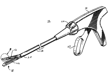
[0033] Referring to FIG. 1, there is illustrated surgical stapling instrument
10
incorporating one embodiment of an anvil assembly 12. Surgical stapling
instrument 10
generally includes a pistol grip style handle 14 having an elongate tubular
member 16 extending
distally from handle 14. An end effector 18 extends distally from a distal end
20 of elongate
tubular member 16 and includes anvil assembly 12 and a staple cartridge 22.
Anvil assembly 12
is movably mounted relative to staple cartridge 22. A trigger 24 is provided
on handle 14 and is
operable to move anvil assembly 12 from an open position spaced apart from
staple cartridge 22
to a closed position bringing anvil assembly 12 into close cooperative
alignment with staple
cartridge 22. A rotation knob 26 is provided on handle 14 to rotate and orient
end effector 18
relative to a tissue being operated upon.
[0034] Referring now to FIG. 2, there is disclosed a series of surgical
staples 28a, 28b,
28c, etc. which have been formed over a reinforcing member or wire 30. Wire 30
is provided to
ensure uniform clamping pressure along the length of a pair of tissue edges
being stapled
-6-
CA 02749454 2011-08-16
together. This is particularly advantageous where staples 28a, 28b, 28c are
formed of a relatively
flexible material which may be insufficient to uniformly clamp the tissues by
themselves. The
disclosed staples 28a, 28b, 28c, etc. and reinforcing member or wire 30 may be
formed from a
variety of materials. These materials may include metal materials such as, for
example, stainless
steel, titanium, etc. Alternatively, they may be formed from a variety of
polymeric or absorbable
materials. Staples 28, 28b and 28c are shown in the fully formed state after
having been driven
into anvil assembly 12. The following discussion of the disclosed staples will
be given with
regard to staple 28a.
[00351 Staple 28a generally includes a backspan 32 having first and second
legs 34 and
36 extending from backspan 32 and terminating in first and second tissue
penetrating tips 38 and
40. First and second legs 34 and 36 include respective first portions 42 and
44 extending from
backspan 32. Second portions 46 and 48 of first and second legs 34 and 36
extend from
respective first portions 42 and 44 and terminate in tissue penetrating tips
38 and 40.
[00361 In the preformed state, first and second legs 34 and 36 are generally
straight. For
example, first portion 42 and second portion 46 of first leg 34 are straight
and lie along a
common axis y-y. However, in the fully formed state, the second portions of
each leg, for
example, second portion 46 of first leg 34 forms a bend or a hook which lies
outside of a plane
defined by axis y-y of first portion 42 and a longitudinal axis x-x of
backspan 32.
[00371 Referring now to FIG. 3, anvil assembly 12 generally includes
reinforcing
member or wire 30 and an anvil member 50 having an anvil face 52. Anvil member
50 includes
a knife slot 54 extending substantially the length of the anvil member 50.
Knife slot 54 is
provided to sever tissues captured between anvil assembly 12 and staple
cartridge 22. Rows of
staple bending pockets 56 and 58 extend lengthways along anvil face 52 and on
either side of
-7-
CA 02749454 2011-08-16
knife slot 54. Rows of staple bending pockets 56 and 58 are provided to form
the second
portions of each leg of the disclosed staples into their bent or hooked shape
as described in more
detail hereinbelow.
[0038] In order to temporarily support a reinforcing member such as, for
example, wire
30, on anvil face 52, a pair of longitudinal troughs or channels 60 and 62
extend longitudinally
along anvil face 52 and extend across rows of staple bending pockets 56 and
58.
[0039] Referring now to FIG. 4, rows of staple bending pockets 56 and 58 each
include
pairs of staple bending pockets 64 and 66 respectively, for forming the legs
of the disclosed
staples about tissue. For example, pair of staple bending pockets 64 includes
a first, generally
oval staple bending pocket 68 and a second, generally oval staple bending
pocket 70. As noted
hereinabove, second portions 46 and 48 of staple 28a are formed into a bent or
hooked
configuration substantially perpendicular to longitudinal axis x-x of backspan
32. In order to
obtain this perpendicular orientation, anvil member 50 includes a longitudinal
axis A-A and
staple bending pockets 68 and 70 are oriented perpendicular to longitudinal
axis A-A.
Specifically, longitudinal axis B-B of oval staple bending pocket 68 is
perpendicular to
longitudinal axis A-A of anvil member 50.
[0040] Referring for the moment to FIGS. 5 and 6, as noted hereinabove, trough
or
channel 60 is provided to support wire 30 along anvil face 52 of anvil member
50 and over the
rows of staple bending pockets. As best shown in FIG. 5, where wire 30 passes
over a staple
bending pocket such as, staple bending pocket 68, it is supported within
trough 60 a sufficient
height h to allow the second portion of the disclosed surgical staples to pass
beneath wire 30 and
allow it to be bent within staple bending pocket 68.
-8-
CA 02749454 2011-08-16
[0041] Referring now to FIG. 6, and as noted hereinabove, wire 30 is
temporarily
supported along anvil face 52 within trough 60. In order to prevent
inadvertent or premature
release of wire 30 from anvil member 50, trough 60 is formed with an opening
72 which is
slightly less than the width of wire 30 in order to temporarily pinch or
retain wire 30 within
trough 60.
[00421 It should be noted that the reinforcing member can comprise a wire,
suture, strand
of material, strip of material, or tab of material. The reinforcing member is
in certain preferred
embodiments less in width than the width of the staple bending pockets. The
reinforcing
member can extend in length across more than one staple bending pocket.
[00431 Referring now to FIGS. 7-10, the use of anvil assembly 12, including
reinforcing
wire 30, and a disclosed staple such as, for example, staple 28a to secure a
pair of tissue sections
together will now be described. As noted hereinabove, surgical stapling
instrument 10 includes
an end effector 18 extending distally from a distal end 20 of elongate member
16 which includes
anvil assembly 12 and staple cartridge 22. The anvil assembly 12, discussed
above with regard to
FIGS. 2 through 6, and the staple cartridge 22 are movable relative to one
another so that tissue
can be clamped therebetween. As best shown in FIG. 7, anvil member 50 includes
a pair of
proximal staple bending pockets 74 and 76 which are identical to staple
bending pockets 68 and
70 described hereinabove. Staple cartridge 22 generally includes a body
portion 78 having a
plurality of staple holding pockets such as, for example, staple holding
pockets 80, 82, 84 etc.
which are provided to retain surgical staples 28a, 28b, 28c etc. Pushers 86,
88, 90 etc. are
provided within staple holding pockets 80, 82 and 84, respectively, to support
the surgical staples
contained therein. A handle is at the proximal end of the elongate member 16.
A drive bar 91
(FIG. 9) is operatively associated with trigger 24 on surgical stapling
instrument 10 (FIG. 1) for
-9-
CA 02749454 2011-08-16
translating the drive bar 91 through the staple cartridge. A sled 92 is
positioned adjacent the
drive bar 91. Drive bar 91 and sled 92 are provided to drive the disclosed
surgical staples such
as, surgical staple 28a out of staple pocket 80 and toward staple bending
pockets 74 and 76 in
anvil member 50. In certain embodiments, the sled has ramped or wedge-shaped
surfaces for
interacting with staple pushers. As the drive bar is translated through the
staple cartridge, the
sled is translated in the same direction, pushing the staple pushers, and the
staple pushers drive
the staples out of the body portion 78 against the anvil member. The sled and
pushers disclosed
in U.S. Patent Nos. 5,762,256 and 5,865,361, the entire disclosures of which
are hereby
incorporated by reference herein, can be used.
[00441 With reference to FIGS. 7 and 8, in the initial position, the
longitudinal axes of
the legs of these disclosed surgical staples are offset relative to wire 30
which is suspended
through the staple bending pockets. Specifically, for example, longitudinal
axis y-y of first leg
34 of staple 28a is offset relative to the center of staple bending pocket 74
(FIG. 8). This allows
first leg 34 to enter staple bending pocket 74 and pass around wire 30 during
formation. While
only staple bending pocket 74 is illustrated as being offset relative to first
leg 34, it should be
understood that all the staple bending pockets in anvil member 50 are offset
relative to the staple
legs to be formed therein so as to allow all staple legs to enter the staple
bending pockets and
pass around wire 30.
[0045] As shown in FIGS. 7 and 8, initially anvil member 50 is moved to the
closed
position relative to staple cartridge 22 by a clamping bar 94 to thereby
capture a pair of tissue
sections such as, for example, for tissue section A and tissue section B
between anvil face 52 of
anvil member 50 and in the cartridge face 96 of staple cartridge 22.
-10-
CA 02749454 2011-08-16
[0046] Referring now to FIGS. 9 and 10, once anvil member 50 has been moved to
the
closed position relative to staple cartridge 22, trigger 24 of surgical
stapling instrument 10 (FIG.
1) is activated to drive drive bar 92 distally within staple cartridge 22. As
drive bar 92 moves
distally, drive bar 92 engages and moves pusher 86 upwardly within staple
holding pocket 80 to
thereby drive first and second legs 34 and 36 into staple bending pockets 74
and 76.
[0047] With specific reference to FIG. 10, as the legs are driven toward their
respective
staple bending pockets such as, for example, as second leg 36 is driven toward
staple bending
pocket 74, tissue penetrating tip 40 passes into staple bending pocket 74 and
around wire 30 to
thereby form second portion 48 of second leg 36 into a bent or hooked
configuration about wire
30. This unique method of forming a leg of the surgical staple allows the
additional material of
second section 48, proximal to tissue penetrating tip 40, to again penetrate
into tissue section A
to further secure surgical staple 28a through tissue sections A and B.
[0048] As best shown in FIG. 11, tissue sections A and B are secured together
by
surgical staples 28a, 28b, 28c, etc. and the clamping of tissue sections A and
B is further
reinforced by the presence of wire 30 secured to the surface of tissue section
A by the bent
respective surgical staples. It should be further noted, in this particular
configuration, the bent or
hooked portions such as, for example, second portion 48 of surgical staple 28a
faces away from
the cut edges Ac and Be formed by a knife blade (not shown) passing through
knife slot 54 in
anvil member 50.
[0049] Referring now to FIG. 12, there is disclosed another embodiment of a
reinforcing
member or wire 98 having a plurality of surgical staples 100, 102 and 104
formed about wire 98.
Surgical staple 100, in the formed condition, is identical to surgical staples
102 and 104 in their
formed conditions and generally includes a backspan 106 having a first leg 108
and a second leg
-11-
CA 02749454 2011-08-16
110 extending from backspan 16. First and second legs 108 and 110 terminate in
respective
tissue penetrating tips 112 and 114. First leg 108 includes a first portion
116 and second leg 110
includes a first portion 118. First leg 108 includes a second portion 120 and
second leg 110
includes a second portion 122.
[0050] As shown, backspan 106 has a longitudinal axis x-x and first portion
116 of first
leg 108 has a longitudinal axis y-y which is perpendicular to longitudinal
axis x-x of backspan
106 to define a plane. First portion 118 of second leg 110 is also
perpendicular to backspan 106
and lies within the same plane. As shown, second portions 120 and 122 of first
leg 108 and
second leg 110, respectively, extend outwardly from the plane defined by
backspan 106 and first
portions 116 and 118. In this particular embodiment, second portions 120 and
122 angle
inwardly toward backspan 106 and are formed within length Ll of backspan 106.
[0051] Referring now to FIG. 13, in order to form surgical staple 100 into the
disclosed
configuration, there is provided an alternative embodiment of an anvil member
124 having an
anvil face 126. The anvil member 124 forms part of a surgical stapling
instrument, as discussed
above in connection with FIGS. 1 and 7 through 10. Anvil member 124 includes a
knife slot 128
and rows of staple bending pockets 130 and 132 formed in anvil face on either
side of knife slot
128. Similar to anvil member 50 described hereinabove, anvil member 124
includes a pair of
channels 134 and 136 extending across anvil face 126 and across rows of staple
bending pockets
130 and 132. Channels 134 and 136 are provided to retain a reinforcing member
or wire 98 in a
manner substantially described hereinabove with regard to wire 30.
[00521 In order to form second portions 120 and 122 into their respective bent
configurations directed inwardly towards backspan 106, row of staple bending
pockets 130
includes a first staple bending pocket 138 and a second staple bending pocket
140. As shown,
-12-
CA 02749454 2011-08-16
first staple bending pocket 138 has an axis C-C and second staple bending
pocket 140 has an axis
D-D both of which are oriented at an angle which converges toward knife slot
128 and is at an
angle other than 90 with respect to longitudinal axis E-E of anvil member
124. It should be
noted that, unlike the previous embodiment, staple bending pockets 138 and 140
angle inwardly
toward knife slot 128 such that, upon formation, bent second portions 120 and
122 of surgical
staple 100 angle inwardly and face edges of tissue cut by a knife blade (not
shown) passing
through knife slot 128.
[0053] With reference to FIG. 14, there is disclosed another embodiment of a
reinforcing
member or wire 142 having a plurality of staples 144, 146 and 148 formed about
wire 142. As
with prior series of staples, surgical staple 144, in the formed condition, is
identical to surgical
staples 146 and 148 and generally includes a backspan 150 having a first leg
152 and a second
leg 154 extending from backspan 150 and terminating in respective tissue
penetrating tips 156
and 158. First leg 152 includes a first portion 160 and second leg 154
includes a first portion
162. Similar to prior embodiments, first leg 152 includes a second portion 164
and second leg
154 includes a second portion 166.
[0054] Backspan 150 has a longitudinal axis x-x and first portion 160 of first
leg 152 has
a longitudinal axis y-y which is perpendicular to longitudinal axis x-x of
backspan 150 to define
a plane. First portion 162 of second leg 154 is also perpendicular to backspan
150 and lies
within the plane. As shown, second portions 164 and 166 of first leg 152 and
second leg 154,
respectively, extend outward of the plane defined by backspan 150 and first
portions 160 and
162. In this particular embodiment, second portions 164 and 166 are parallel
to each other and
form an angle other than 90 with respect to longitudinal axis x-x of backspan
150.
-13-
CA 02749454 2011-08-16
[00551 Referring to FIG. 15, in order to form surgical staple 144 into the
disclosed
configuration, there's provided a further alternative embodiment of an anvil
member 168 having
an anvil face 170. The anvil member 168 forms part of a surgical stapling
instrument, as
discussed above in connection with FIGS. I and 7 through 10. Anvil member 168
includes a
knife slot 172 extending substantially the length of anvil member 168 and rows
of staple bending
pockets 174 and 176 formed on either side of knife slot 172. Anvil member 168
additionally
includes channels 178 and 180 extending across anvil face 170 and across rows
of staple bending
pockets 174 and 176 to temporarily secure wire 142 in a manner described
hereinabove with
regard to wire 30.
[0056) In order to form second portions 164 and 162 into their angled and
parallel bent
configurations with respect to backspan 150, row of staple bending pockets 174
includes a first
staple bending pocket 182 and a second staple bending pocket 184. First staple
bending pocket
182 has a longitudinal axis F-F which is parallel to a longitudinal axis G-G
of second staple
bending pocket 184. Both first and second staple bending pockets 182 and 184
form an angle
with respect to a longitudinal axis H-H of anvil member 168.
[00571 Referring now to FIG. 16, there is disclosed a further embodiment of a
reinforcing
member or wire 186 having surgical staples 188, 190 and 192 formed about
reinforcing wire
186. Surgical staple 188 is identical to surgical staples 190 and 192 and
generally includes a
backspan 194 having a first leg 196 and a second leg 198 extending from
backspan 194. Tissue
penetrating tips 200 and 202 are formed on first and second legs 196 and 198,
respectively. First
and second legs 196 and 198 include respective first portions 204 and 206 and
respective second
portions 208 and 210. First portion 204 of first leg 196 has a longitudinal
axis y-y which is
perpendicular to a longitudinal axis x-x of backspan 194 and defines a plane
there between. As
-14-
CA 02749454 2011-08-16
with previous embodiments, in the formed condition, second portions 208 and
210 extend
beyond the plane defined by first portion 204 and backspan 194.
[0058] In this particular embodiment, second portions 208 and 210 are angled
or splayed
outwardly relative to backspan 194 such that they extend beyond a length L2 of
backspan 194.
[0059] In order to form surgical staples 188, 190 and 192 into their disclosed
configurations, there is provided an anvil member 212 (FIG. 17) having an
anvil face 214. The
anvil member 212 forms part of a surgical stapling instrument, as discussed
above in connection
with FIGS. 1 and 7 through 10. Anvil member 212 includes a longitudinally
extending knife slot
216 and rows of staple bending pockets 218 and 220 formed in anvil face 214 on
either side of
knife slot 216. A pair of channels 222 and 224 is provided across anvil face
214 and through
rows of staple bending pockets 218 and 220 to hold wire 186.
[0060] Row of staple bending pockets 218 includes a first staple bending
pocket 226 and
a second staple bending pocket 228. First staple bending pocket 226 has a
longitudinal axis I-I
and second staple bending pocket 228 has a longitudinal axis J-J both of which
are oriented at an
angle which converges away from knife slot 216 and is at an angle other than
90 with respect to
a longitudinal axis K-K of anvil member 212.
[0061) With reference to FIG. 18, there is disclosed a further alternative
embodiment of
an anvil member 230 suitable for use in forming the disclosed surgical staples
about reinforcing
member or wire. The anvil member 230 forms part of a surgical stapling
instrument, as
discussed above in connection with FIGS. 1 and 7 through 10. Anvil member 230
includes an
anvil face 232 having a knife slot 234 extending longitudinally through anvil
member 230.
Rows of staple bending pockets 236, 238, 240 and 242 are provided alongside
knife slot 234. As
with the prior anvil embodiments, longitudinally extending channels 244, 246,
248 and 250
-15-
W~,y.
CA 02749454 2011-08-16
extend through rows of staple bending pockets 236, 238, 240 and 242 to
removably support
lengths of reinforcing member across the staple pockets such as, for example,
staple pockets 252
and 254. It should be noted that in this, as well as in prior, alternative
embodiments of the
disclosed anvil members, staple pockets 252 and 254 may assume any of the
configurations and
orientations previously disclosed. For example, all the staple pockets 252 and
254 in anvil
member 230 may be oriented in the same or in differing directions.
[0062] It is contemplated that the fastener assembly having one or more
reinforcing
members and staples as discussed above in connection with FIGS. 2 through 6
and 11 through 18
can be used in surgical stapling instruments that have circular or arcuate
anvils, and/or surgical
stapling instruments in which the staples are driven against the anvil in the
same direction as the
anvil (or cartridge) moves to clamp tissue.
[0063] It will be understood that various modifications may be made to the
embodiments
disclosed herein. For example, the disclosed staple bending pockets may assume
shapes other
than oval such as, for example, circular, figure 8, etc. Further, as noted
hereinabove, the
disclosed reinforcing members may include materials other than wire such as
for example thin
strips of webbing material, flat ribbons of metallic or polymeric materials,
etc. so long as the
links of reinforcing material do not completely occlude the disclosed staple
bending pockets.
Therefore, the above description should not be construed as limiting, but
merely as
exemplifications of particular embodiments. Those skilled in the art will
envision other
modifications within the scope and spirit of the claims appended hereto.
-16-