Note: Descriptions are shown in the official language in which they were submitted.
CA 02749555 2011-07-13
WO 2010/083135 PCT/US2010/020694
ASPIRATED WOUND DRESSING
FIELD OF THE INVENTION
The present invention relates to the field of wound dressings that use
aspiration
> to remove wound exudate.
BACKGROUND TO THE INVENTION
Wound exudate can be described as the liquid produced from chronic wounds,
fistula, or acute wounds once haemostasis has been achieved. For centuries,
the
production of exudate was regarded as inevitable with certain types of wound,
and
inconsequential with respect to wound healing.
More recently, considerable attention has been given to the development of
wound dressings that prevent the accumulation of large volumes of fluid within
a wound,
and also prevent the fluid from spreading over the surrounding healthy tissue.
This is
because excessive wound exudate can cause maceration of the peri-wound skin,
which
> in turn can lead to infection. One technique known in the art is the
application of suction
through the wound dressing, to create and maintain negative pressure at the
wound
site. Negative pressure means pressure below surrounding atmospheric pressure.
Such a technique is referred to in the art as Topical Negative Pressure (TNP).
This is
believed by some researchers to aid drainage of wound exudate away from the
wound
bed, reduce infection rates, and increase localized blood flow.
Maintaining negative pressure at the wound site may create some practical
problems:
(i) The negative pressure may be able to draw tissue growth into the pores of
a foam piece inside the wound dressing. This can result in discomfort to the
patient
> during use of the device, especially when the dressing is removed or
replaced.
Removal or replacement of the dressing may also cause damage to that newly
grown
tissue.
(ii) The wound is vulnerable to drying out of wound exudate. This condition
may be undesirable because exudate is believed to contain a complex mixture of
bioactive molecules that have both positive and negative effects. While
removal of
excess exudate is desirable, removal of all exudate may hinder rather than aid
wound
1
CA 02749555 2011-07-13
WO 2010/083135 PCT/US2010/020694
healing. Proper use of the wound dressing may depend to a large extent on the
expertise of medical staff in assessing the rate of production of wound
exudate at the
wound site, and adjusting the negative pressure accordingly. If frequent
removal of the
dressing is required to assess the state of the wound, this merely exacerbates
> discomfort caused by drawback (i) above.
Some of the potential drawbacks may be partly mitigated by the use of hydro-
fiber as described in U.S. Patent Publication No. 2006/0100594.
The present invention has been devised bearing potential issues in mind.
SUMMARY OF THE INVENTION
Broadly speaking, one aspect of the invention is to apply suction for removing
wound exudate, in a manner that avoids creation of substantial negative
pressure at the
wound site.
Such a technique permits effective removal of exudate, without the potential
drawbacks of topical negative pressure. In particular, issues of tissue growth
into the
> wound dressing itself, and associated patient discomfort, can be avoided.
In one form, the wound dressing comprises a liquid permeable pressure barrier
between a point at which suction is applied, and the region interfacing a
wound site.
The barrier may, for example, comprise foam. The suction creates a pressure
differential across the barrier and/or a local pressure gradient within the
pressure
barrier, thereby allowing efficient removal of liquid exudate that is in
contact with or
absorbed within the pressure barrier, without subjecting the wound site to
substantial
negative pressure.
Additionally or alternatively, the wound dressing comprises one or more vent
passages for equalizing and/or stabilizing an interior space and/or wound
interface
> region of the wound dressing at surrounding atmospheric pressure. The vent
passages
may, for example, comprise pores, capillaries, or porous material in an air-
venting
portion of the wound dressing, such as an air-venting backing or cover.
Another independent aspect of the invention is the use of porous material for
an
air-venting portion of an aspirated wound dressing. The porous material is
permeable
to air, but substantially impermeable to water vapor and liquid. This
contrasts with the
techniques of the prior art in which either (i) a cover layer of a dressing is
made of semi-
2
CA 02749555 2011-07-13
WO 2010/083135 PCT/US2010/020694
permeable material allowing moisture-vapor transpiration through the material,
or (ii) the
cover layer is generally impermeable for both gas and liquid. The term "semi-
permeable" (as used for example in U.S. Patent No. 4,969,880) means that a
material is
moisture-vapor permeable, but impermeable to liquids. The previous purpose of
a
> moisture-vapor permeable membrane was to allow exudate moisture to evaporate
through the membrane, as a way of promoting healing by preventing maceration
of both
normal skin and the wound.
In contrast, the present aspect of the invention may provide significant and
surprising advantages not contemplated by the prior art. It enables air to
enter the
wound dressing, in order to equalize or stabilize the pressure with respect to
external
atmospheric pressure, which is significant as explained above for avoiding
exposing the
wound to substantial negative pressure. At the same time, outside sources of
moisture
and moisture vapor are prevented from ingress into the dressing, thereby
reducing risk
of contamination and infection. All removal of moisture occurs via the
aspiration
> system, and there is no ingress of external moisture or moisture vapor,
thereby making
moisture level in the dressing easier to manage in a controllable, predictable
way.
This aspect of the invention has an additional synergy when a liquid sensor is
used for sensing liquid within the wound dressing. The idea of air-permeable
material
that obstructs passage therethrough of moisture vapor and liquid, in
combination with a
liquid sensor for controlling aspiration responsive to detection of liquid by
the sensor,
represents a fundamentally new approach for moisture and exudate management,
while
permitting entry of air into the dressing to equalize or stabilize the
interior pressure with
respect to external atmospheric pressure, and can avoid the negative effects
of TNP.
In one form, a material is considered to be air-permeable, and substantially
> impermeable to moisture-vapor and liquid, when the moisture vapor
transmission rate is
no more than 1 gm/min at 10 mbar and when the air transmission rate in cc/min
is at
least 10 times greater than the moisture vapor transmission rate (MVTR in
gm/min),
more preferably at least 20 times greater, more preferably at least 50 times
greater,
more preferably at least 100 times greater. Preferably, the moisture vapor
transmission
rate is no more than 0.5 gm/min at 10 mbar. More preferably, the moisture
vapor
3
CA 02749555 2011-07-13
WO 2010/083135 PCT/US2010/020694
transmission rate is no more than 0.1 gm/min at 10 mbar. More preferably, the
moisture
vapor transmission rate is no more than 0.01 gm/min at 10 mbar.
An embodiment of a wound dressing for an aspirated wound dressing system,
according to the present invention includes:
> a wound interface region for contacting or facing a wound site;
an aspiration port for receiving suction for aspiration of wound exudate;
a liquid permeable pressure barrier disposed between the wound interface
region
and the aspiration port for substantially preventing application of negative
pressure from
the aspiration port to the wound interface region;
at least one atmospheric vent or porous material for equalizing with
atmosphere
the pressure at the wound interface region; and
a liquid sensor for sensing liquid within the wound dressing, for controlling
application of negative pressure by an aspiration unit.
These and other aspects of the invention are defined in the claims. While
certain
> features and ideas are defined above and in the claims, protection may be
claimed for
any novel feature or idea disclosed herein and/or in the drawings whether or
not
emphasis has been placed thereon.
BRIEF DESCRIPTION OF THE DRAWINGS
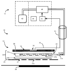
Fig. 1 is a schematic block diagram of a first embodiment of wound management
system, including a wound dressing and an aspiration unit for aspirating
excess exudate
from the wound dressing, the diagram including a schematic sectional view of
wound
dressing components.
Fig. 2 is a schematic sectional view showing a modified version of the wound
dressing of Fig. 1.
> Fig. 3 is a schematic diagram illustrating a vacuum relief means in the
cover for
the second embodiment of the wound dressing.
Fig. 4 is a schematic diagram showing a modified arrangement of the vacuum
relief means.
Fig. 5 is a schematic diagram illustrating flow resistances and pressure drops
within a third embodiment of the wound dressing.
4
CA 02749555 2011-07-13
WO 2010/083135 PCT/US2010/020694
Fig. 6 is a schematic diagram showing for the fifth embodiment a relation
between the signal from the liquid sensor, and responsive thereto the
application of
negative pressure.
DETAILED DESCRIPTION OF PREFERRED EMBODIMENTS
> Preferred embodiments of the invention are now described with reference to
the
drawings. The same reference numerals are used to depict the same or
equivalent
features in each embodiment.
First Embodiment
Referring to Fig. 1, a wound management system 10 generally comprises a
wound dressing 14 and an aspiration unit 12 for applying suction to the wound
dressing
14 to aspirate excess exudate. The field of wound dressings with exudate
aspiration is
quite unique, and very different from the field of, for example, urine
removal. Urine is
usually discharged as a surge of liquid, and a urine removal system should
remove all
urine to leave the skin dry in order to avoid irritation and infection. In
contrast, wound
> exudate is not discharged in a surge, and it is not desirable to remove all
of the wound
exudate. The exudate contains a complex mixture of bioactive molecules that
have
both positive and negative effects. While removal of excess exudate is
desirable,
removal of all exudate may hinder rather than aid wound healing. Instead, the
present
embodiment aims to manage the amount of wound exudate, and remove excess from
the wound site. Also, the present embodiment aims to avoid maintenance of
negative
pressure at the wound site, in order to avoid the potential complications
associated with
topical negative pressure.
The wound dressing 14 is preferably attachable to the patient's skin by means
of
an adhesive pad 26. The absence of substantial negative pressure at the wound
site 18
> means that the wound dressing 14 will not be held in position by substantial
suction,
and the adhesive pad 26 compensates to positively locate the wound dressing
14. In
the form illustrated in Fig. 1, the adhesive pad 26 extends over the wound
site 18, and
has perforations or apertures 27 to permit passage of exudate from the wound
site 18
into the wound dressing 14. In the form illustrated in Fig. 2, the adhesive
pad 26 has a
closed loop shape that circumscribes the periphery of the wound site 18. The
adhesive
pad 26 is made of a skin-friendly medical grade adhesive. Examples of suitable
CA 02749555 2011-07-13
WO 2010/083135 PCT/US2010/020694
adhesives include pressure-sensitive adhesives that may be any of
hydrocolloid,
polyurethane, acrylic, thermoplastic elastomer (TPE), hydrogel, or silicone-
based. The
portion of the wound dressing 14 communicating with the wound site 18 is
referred to
herein as the wound interface region 14a.
> The wound dressing 14 generally comprises a cover 16, a liquid handling
material 24 (24a, 24b), and an aspiration port 22. The adhesive pad 26 may
also form
an integral part of the wound dressing 14, or it may be a separate component.
The
cover 16 extends over the wound site 18, and overlaps healthy periwound
tissue. The
cover 16 is impermeable to liquids and/or water vapor, in order to contain
exudate, and
to prevent ingress of external liquids. The cover may, for example, be made of
flexible
polyurethane (PU) foam, polyurethane (PU) foam laminated with a film, or low
durometer polyethylene (PE) foam.
The liquid handling material 24 may serve as any one, or any combination of
two
or more, of (i) a pressure barrier, (ii) a material for collecting liquid
exudate by sorption,
> and allowing the exudate to be pumped away under suction, (iii) a material
for
maintaining a moist environment at the wound surface while permitting excess
exudate
to be pumped away under suction.
The liquid handling material 24 (24a, 24b) may, for example, be a material for
sorbing (adsorbing or absorbing) exudate without gelling. Such a material may
be non-
woven and/or foam. Such a non-woven could be hydrophobic or hydrophilic,
synthetic
or natural. The liquid handling material 24 (24a, 24b) may allow liquid to
wick in all
directions, in order to permit transfer of liquid within the liquid handling
material 24 (24a,
24b) to the point of aspiration. The liquid handling material 24 (24a, 24b)
may
alternatively be, or comprise, a material that forms a cohesive gel when
wetted with
> wound exudate. Such gelling material may be a fibrous blend or fibrous
material (e.g., a
non-woven). An example is the wound contact layer of the Versiva dressing
(ConvaTec Inc., Skillman, NJ) or a fibrous mat of sodium
carboxymethylcellulose. A
fibrous mat of sodium carboxymethylcellulose is available as AQUACEL dressing
from
ConvaTec Inc., as is a similar dressing further including silver. Other
exemplary
materials for the liquid handling material 24 include MedicelTM and
CarboxflexTM (which
6
CA 02749555 2011-07-13
WO 2010/083135 PCT/US2010/020694
provides an odor absorbent layer with fibrous material for wicking liquid away
from the
odor absorbent).
In a further form, a combination of both a non-gelling liquid handling
material 24a
and a (fibrous) gelling material 24b may be used, for example, in distinct
layers. The
> materials 24a, 24b may be bonded to each other, or they may be contained as
separate
layer components within the wound dressing 14. The layer closest to the wound
site 18,
for example, the gelling material 24b, may be perforated to allow excess
exudate to be
absorbed by another layer, for example, the non-gelling material 24a. In such
a
combined arrangement, the gelling material 24b mainly provides the property
(iii)
mentioned above, while the non-gelling material 24a mainly provides the
properties (i)
and/or (ii).
The aspiration port 22 comprises suitable tubing 22a (e.g., silicone tubing)
extending into the wound dressing 14 for delivering aspiration suction from
the
aspiration unit 12. In the form illustrated, the tubing 22a extends through a
peripheral
> side edge of the wound dressing 14, although the tubing 22 could enter the
wound
dressing 14 at any suitable point, such as passing through an aperture in the
cover 16.
The tubing 22a comprises an aspiration interface portion 22b, comprising one
or more
apertures or perforations, through which the suction is applied to the wound
dressing 14
for drawing away the excess exudate, described later.
A preferred feature of the present embodiment is that the wound dressing 14 is
configured such that the wound interface region 14a is not substantially
exposed to the
negative pressure applied to the aspiration port 22, and so the wound site 18
is also not
substantially exposed to such negative pressure. As used herein, the negative
pressure
is defined as a pressure differential with respect to ambient atmospheric
pressure. The
> magnitude of the negative pressure refers to the magnitude of difference
with respect to
the ambient atmospheric pressure. A large negative pressure means a large
pressure
difference from atmospheric pressure, and a smaller negative pressure means a
pressure closer to atmospheric pressure. Conventional TNP devices maintain a
negative pressure between 75mm Hg to 125mm Hg continuously or intermittently.
Atmosphere pressure is equal to 760mm Hg (i.e., 101K Pascal or 1,013 mbar).
The
wound dressing 14 is configured such that, in use, any negative pressure at
the wound
7
CA 02749555 2011-07-13
WO 2010/083135 PCT/US2010/020694
interface region 14a is not more than (and preferably less than) about 10% of
the
negative pressure (75mm Hg) applied at the aspiration port 22, preferably not
more than
about 5% (38mm Hg) more preferably not more than about 4% (30mm Hg), more
preferably not more than about 3% (23mm Hg), more preferably not more than
about
> 2% (15mm Hg), and more preferably not more than about 1% (7.6mm Hg).
Avoiding exposure of the wound site 18 (wound interface region 14a) to
substantial negative pressure can avoid many of the problems of the prior art.
In
particular, it can avoid the issues associated with new tissue growth drawn
into the
wound dressing components, and the pain and potential tissue damage upon
removal
or replacement of the wound dressing 14. It can also avoid drying out of the
wound
exudate.
The present embodiment avoids negative pressure at the wound interface region
14a, by one or both of:
(i) the provision of a pressure barrier within the wound dressing 14, and/or
> (ii) the provision of one or more atmospheric vents or porous materials for
equalizing
the pressure at the wound interface region 14a.
As mentioned above, the pressure barrier may be implemented by at least a
portion of the liquid handling material 24. The aspiration interface portion
22b of the
port tubing 22a is separated from the wound interface region 14a by at least a
portion of
the liquid handling material 24, for example, the non-gelling material 24a.
The pressure
barrier characteristic is provided, for example, by virtue of suitably small
pores in the
liquid handling material. In the form illustrated in Fig. 1, the aspiration
interface portion
22b is disposed within the exudate handling layer 24, for example, the non-
gelling layer
24a. In the form illustrated in Fig. 2, the aspiration interface portion 22b
is disposed
> behind the exudate handling material 24, and is sealed by an impermeable
membrane
22c such that the aspiration interface portion 22b communicates with the
interior of the
wound dressing 14 only via the liquid handling material 24.
Additionally or alternatively, atmospheric vents 28 are provided for
equalizing the
pressure at the wound interface region 14a. The atmospheric vents 28 may be
capillaries or pores in the cover 16. Atmospheric vents 28 can be also made
from
porous materials, such as air-breathable membranes, air-breathable nonwovens,
air-
8
CA 02749555 2011-07-13
WO 2010/083135 PCT/US2010/020694
breathable foams, etc. Among these porous materials, air-breathable membranes
and
air-breathable non-wovens are preferred due to their ability of preventing the
liquid and
water vapor from flowing through (e.g., using hydrophobic treatment) while
allowing the
air to pass. Air-breathable membrane can, for example, be made from polymers
> selected from high density polyethylene (HDPE), ultra high molecular weight
polyethylene (UHMWPE), polypropylene (PP), poly(vinylidene fluoride) (PVdF),
poly(tetrafluoro ethylene) (PTFE). These polymers can be sintered or stretched
to
create the porous structure to allow the air to flow through. These porous
materials,
such as membranes and non-wovens, can optionally be hydrophobic treated to
impart
or increase the resistance to liquids (i.e., exudate) and moisture vapor, but
the material
remains permeable to air. These porous materials can be also made into various
forms, such as a low profile rigid part, a semi-rigid part, or a flexible
membrane. The air
flow rate of atmospheric vent and porous material is at least 5 cc/min at 10
mbar,
preferably at least 50 cc/min at 10 mbar, and more preferably at least 100
cc/min at 10
> mbar. The cover is impermeable to water vapor or liquids in order to prevent
liquid
ingress into the wound dressing 14, and to stop the passage of exudates. The
atmospheric vents 28 communicate with the interior of the wound dressing 14,
in
particular with the wound interface region 14a.
In use, wound exudate is sorbed (adsorbed and/or absorbed) by the liquid
handling material 24. Upon application of suction via the port 22, a localized
pressure
gradient in at least a portion of the liquid handling material 24 draws or
wicks excess
exudate to the aspiration interface portion 22b at which the exudate is
aspirated away
via the port 22. The pressure at the wound interface region 14a remains at
substantially
atmospheric pressure by virtue of the pressure barrier characteristic of the
liquid
> handling material 24, or the atmospheric vents or porous materials 28, or a
combination
of above. In the absence of substantial negative pressure at the wound
interface region
14a, the liquid handling material 24 plays a significant role in collecting
exudate from the
wound surface, and transporting the exudate to the aspiration interface
portion 22b.
A liquid sensor 30 is provided for sensing exudate within the wound dressing
14,
and for generating a sensor signal 32 for controlling the aspiration unit 12.
The liquid
sensor 30 may be responsive to the proximity and/or the quantity of liquid.
The liquid
9
CA 02749555 2011-07-13
WO 2010/083135 PCT/US2010/020694
sensor 30 may be separate or separable from the wound dressing 14, enabling
replacement of the wound dressing 14 without having to use a new sensor 30. In
such
a case, a means is preferably provided for releasably attaching the sensor 30
to the
wound dressing 14. Alternatively, the liquid sensor 30 may be permanently
attached to
> the wound dressing 14 to form an integral unit. With permanent attachment,
the liquid
sensor 30 is intended to be disposed of with the wound dressing 14.
Additionally or alternatively, sensor 30 can be a pressure sensing unit
responsive
to the set point pre-determined in order to avoid exposure of the wound site
18 (wound
interface region 14a) to substantial negative pressure.
The sensor signal 32 is typically an electrical or electronic signal. However,
other
signal forms may be used as desired, for example, optical.
The sensor 30 may generate output signal 32 that varies in accordance with the
sensed parameter(s). For example, the output signal 32 may be a varying analog
signal
(e.g., variable current or voltage), or the output signal 32 may be a digital
signal (e.g., a
> quantized representation, or a variable pulsed representation).
Alternatively, the sensor
signal 32 may be a logical (e.g., binary, or on/off) signal indicating whether
or not the
sensed parameter exceeds or is below one or more thresholds.
The liquid sensor 30 is preferably a non-contact sensor that is able to detect
the
presence or proximity of liquid without contact with the liquid. The feature
of the liquid
sensor 30 being a non-contact sensor provides significant advantages because:
(i) the
non-contact approach automatically avoids any concerns about passing an
electrical
current through liquid in contact with the skin 20 and wound site 18. Instead,
there is no
direct contact between the liquid sensor 30 and the liquid; (ii) the non-
contact approach
means that the liquid sensor 30 is not contaminated by touching the liquid
exudate.
> This allows the liquid sensor 30 easily to be reused with a different wound
dressing 14;
and (iii) the non-contact approach means that the liquid sensor 30 does not
itself have
to be in a sterile condition before use, thus avoiding the difficulty of, or
risk of damage
when, sterilizing the wound management system 10 that does interface
intimately with
the body. The feature of the liquid sensor 30 being coupled to the aspiration
unit 12 by
an electrical connector avoids the expense and fragility associated with using
an optical
fiber connection.
CA 02749555 2011-07-13
WO 2010/083135 PCT/US2010/020694
An optional feature of the invention is that the liquid sensor 30 is separate
from,
or at least separable from, the wound dressing 14. The wound dressing 14 may
be a
disposable item that may be manufactured inexpensively, and disposed of after
a single
use, or a limited number of uses. The liquid sensor 30 may be more expensive,
but
> may be intended to be used multiple times, preferably, with a sequence of
different
wound dressings 14 used during wound treatment. This enables the wound
management system 10 to be produced and used very cost efficiently, since the
disposable components are generally low cost. The higher cost components may
be
used multiple times, and may require infrequent replacement. In one form, the
liquid
sensor 30 is a universal device that may be used with any of a plurality of
different types
of wound 14
Alternatively, the non-contact sensor 30 may be permanently attached to the
wound dressing 14, and not be a re-usable item.
The liquid sensor 30 can take a variety of different forms. The liquid sensor
30 is
> optionally selected from: a capacitance sensor; an ultrasonic sensor; and a
piezo-
electric (or piezo-resonant) sensor. A capacitance sensor detects proximity of
liquid
according to changes in the dielectric effect of liquid proximity, compared to
air
proximity. The dielectric effect affects the electric field in the active zone
around the
sensor, and thus, the effective capacitance in the sensor. The capacitance is
monitored
by any suitable capacitance sensing circuit (not shown), such as an RC
oscillator whose
oscillation frequency and/or whether oscillation occurs, is dependent on the
value of a
resistor in combination with the effective capacitance of the sensor. The
oscillation in
turn triggers an output stage, coupled to an output amplifier, to generate an
output
signal indicative of liquid presence. The capacitance sensing circuit is
preferably
> disposed near or at the liquid sensor 30 (e.g., as part of the liquid sensor
30 itself), or
the capacitance sensing circuit can be disposed at the aspiration unit 12, or
at a point
along electrical connector. A suitable capacitance sensor and capacitance
sensing
circuit are described in U.S. Patent No. 5,576,619, the contents of which are
hereby
incorporated by reference.
The ability to detect liquid has been tested using a capacitance "smart"
sensor
from SIE Sensors. The sensor 30 of dimension 35mm (length) x 22mm (width) x
10mm
11
CA 02749555 2011-07-13
WO 2010/083135 PCT/US2010/020694
(height) was affixed to the external wall of a wound dressing 14. The sensor
30
detected the presence of two test liquids, water and saline solution, as soon
as the
liquid was introduced, and provided an activation signal to the aspiration
unit 12 within
milliseconds. The electric field from the sensor 30 is able to penetrate a
wide variety of
> plastic components (e.g., polyethylene (PE), polypropylene (PP) and
acrylics), either
transparent or opaque, with great sensitivity.
An ultrasonic sensor works using the principle of sonar at the ultrasonic
frequency range. A transducer is resonated at a set frequency to convert
electric
energy into ultrasonic frequency range acoustic energy. The ultrasonic
acoustic waves
are emitted towards a liquid collection region. Energy is reflected either
from the walls if
the region is empty of liquid, or from liquid if present in the region. By
measuring the
time delay for reflected waves to arrive, and comparing this to one or more
pre-
calibrated time delays taken when the liquid collection region is empty, the
presence of
liquid can be reliably and quickly detected. An example of ultrasonic liquid
sensor is
> described in U.S. Patent No. 3,960,007, the content of which is incorporated
herein by
reference. A commercially available ultrasonic sensor is made available by
ZEVEX Inc.
A piezo-electric or piezo-resonant sensor also uses high frequency, e.g.,
ultrasonic energy or acoustic signal, in a similar way to the ultrasonic
sensor described
above. The ultrasonic or acoustic signal could penetrate either transparent or
opaque
plastic walls. An example of piezo-electric sensor is described in U.S. Patent
No.
3,948,098, the content of which is incorporated herein by reference.
The ability to detect liquid has been tested with a piezo-resonant sensor
obtained
from GEMS Sensors. The sensor 30 of diameter 40mm was attached to the external
wall of the wound dressing 14, and detected the presence of liquid as soon as
> introduced.
With the arrangement illustrated in Figs. 1 and 2, the liquid sensor 30 is
disposed
outside the wound dressing 14, or at least outside a liquid collection region
of the wound
dressing 14. The cover 16 is typically made of material through which the
sensing
electric field can pass in the case of a capacitance sensor, or through which
an
ultrasonic vibration can pass in the case of an ultrasonic and/or piezo-
electric sensor.
The cover 16 may be made suitably thin to provide the sensor 30 with the
desired
12
CA 02749555 2011-07-13
WO 2010/083135 PCT/US2010/020694
sensitivity to liquid within the wound dressing 14. Alternatively, the cover
16 may
include a window portion made of material through which the electric field or
ultrasonic
vibration can pass easily if the entire cover 16 is not made of such a
material. In an
alternative embodiment, the housing of the wound dressing 14 can be shaped
into a
> pocket with or without membrane, for receiving and retaining a capacitive,
ultrasonic or
piezo-electric non-contact liquid sensor 30. Such a design also increases the
interface
area between the sensor 30 and the liquid collection region of the wound
dressing 14.
In an alternative embodiment, the sensor 30 is an electro-optical sensor. The
cover 16 comprises a window region (not shown) made of material that is
transparent to
the optical radiation used by the electro-optical sensor. For example, the
optical
radiation may be in the infra-red range, and/or the visible range, and/or
ultra-violet
range. The term "optical" as used herein means that the radiation lies in a
frequency
range that obeys substantially the laws of optics. The electro-optical sensor
comprises
an electro-optical emitter, an electro-optical receiver, and sensing circuitry
for detecting
> the presence of liquid according to the electrical output of the electro-
optical receiver.
The sensing circuitry is preferably disposed at the liquid sensor 30 (e.g., as
part of the
liquid sensor 30), or the sensing circuitry is disposed at the aspiration unit
12, or at a
point along electrical connector 35. An example electro-optical liquid sensor
is
described in U.S. Patent No. 4,354,180, the content of which is incorporated
herein by
reference.
If preferred, the liquid sensor 30 may be disposed at a position (not shown)
in
contact with exudate inside the wound dressing 14, even if the sensor 30 does
not rely
on direct contact to detect the liquid. Such a possibility also enables the
use of a
contact-based sensor 30 instead of a non-contact sensor 30. An example of a
contact-
based sensor 30 is an electrical resistance sensor that detects liquid by
conductance
between electrodes in contact with the liquid.
In the case that the liquid sensor 30 is separate from, or at least separable
from,
the wound dressing 14, the liquid sensor 30 may be held in an operative
position with
respect to the wound dressing 14 by a detachable attachment device (not shown)
for
releasably attaching the liquid sensor 30 to the wound dressing 14. For
example, the
detachable attachment device could comprise a peelable adhesive, or a peelable
13
CA 02749555 2011-07-13
WO 2010/083135 PCT/US2010/020694
mechanical fastener, such as Velcro , or a mechanical coupling based on
interference
fitting, or other mechanical means.
A flexible electrical connector or conduit 35 couples the wound dressing 14 to
the
aspiration unit 12. A releasable connector or an easy release coupling may be
provided
> at one end, or both ends, of the flexible electrical connector 35. The
flexible electrical
connector 35 may be regarded as part of the aspiration unit 12 and/or part of
the wound
dressing 14. The flexible conduit 35 links the port 22 to a suction source 40
within the
aspiration unit 12. The aspiration unit 12 comprises a power supply 38, an
electronic
control unit 44, and the suction source 40. The power supply 38 is selected as
one or
more of: a replaceable battery, a rechargeable battery, radiation collection
panels, and
a main power supply. Preferably, the power supply 38 includes a combination of
a
rechargeable battery and a main power supply; such a combination allows
portable
operation when the wound management system 10 is not connected to a main power
supply, as well as automatic recharging of the battery when the wound
management
> system 10 is coupled to a main power supply. Additionally or alternatively,
the power
supply 38 includes radiation collection panels, such as photovoltaic panels or
cells for
generating electricity from ambient light, which can improve autonomy of
operation or
for charging the rechargeable battery. The power supply 38 may provide power
for any
one or more of: the electronic control unit 44, the liquid sensor (if needed)
30 and any
power needed by the suction source 40. In the present embodiment, the suction
source
40 is an electric pump that operates under control of the electronic control
unit 44. The
pump 40 could be a suction device based on diaphragm, peristaltic, volume
displacement, spring, gravity, siphon, heat-recoverable metal drive, or an in-
line pump.
The flexible conduit 35 is coupled through the pump 40 to a liquid collection
chamber 42
> for collecting exudate removed from the wound dressing 14. The liquid
collection
chamber 42 may either be separate from the aspiration unit 12 (as illustrated)
and
coupled thereto with a suitable connector, or the liquid collection chamber 42
may be
integral with and/or housed in the aspiration unit 12 (arrangement not shown).
In an
alternative form, instead of a pump 40 directly applying suction to the
flexible conduit
35, the suction source 40 may comprise a vacuum chamber charged with a low
pressure vacuum, and an electronically controlled valve for controlling
application of
14
CA 02749555 2011-07-13
WO 2010/083135 PCT/US2010/020694
suction from the vacuum chamber to the flexible conduit 35. A pump may be
provided
for charging the vacuum chamber with the vacuum.
In the present embodiment, it is preferred that application of aspiration
suction is
controlled responsive to the sensor signal 32. This further avoids subjecting
the wound
> dressing 14 to negative pressure unless the sensor 30 detects the presence
of sufficient
liquid exudate within the wound dressing 14. Thus, not only is the wound
dressing 14
configured not to subject the wound site 18 to substantial negative pressure
from the
aspiration port 22, but optionally also the application of negative pressure
at the
aspiration port itself 22 is also reduced, suction being applied only when
judged
necessary in response to the sensor signal 32 from the liquid sensor 30.
It will be appreciated that although the wound dressings 14 shown in Figs.1
and
2 differ in two respects (i.e., the position of the aspiration interface
portion 22b, and the
configuration of the adhesive pad 26), these configurations may be intermixed
as
desired.
> Second Embodiment
The second embodiment has the same construction as described above, but
further refines properties of the atmospheric vent 28. Figs. 3 and 4
illustrate only the
material carrying the vent 28, such as the backing or cover 16, the other
elements of the
wound dressing 14 being as in any of the other embodiments. Additionally or
alternatively to the vent previously described, the atmospheric vent 28
comprises one or
more vacuum relief means 28a (i.e., pressure relief means) which allows air to
flow into
the wound dressing 14 for equalizing and/or stabilizing the interior space of
the wound
dressing 14 when the amount of negative pressure inside the wound dressing 14
is
higher than the set point. Vacuum relief means 28a may, for example, comprise
check
> valve, duckbill valve, umbrella valve, solenoid valve, minivalveball, or a
combination of
any of these. In Fig. 3, the vacuum relief means 28a replaces the previous
porous vent
arrangement 28. In Fig. 4, the vacuum relief means 28a is used in addition to
the
porous vent arrangement 28 previously described, in order to provide
additional
pressure relief via a parallel vent path should the internal negative pressure
exceed the
pre-selected limit. Additionally or alternatively, as depicted by the broken
line, the
CA 02749555 2011-07-13
WO 2010/083135 PCT/US2010/020694
vacuum relief means 28a may be used with the atmospheric vent 28, and mounted
on
the interior side of the cover 16 and/or vent 28, or on the exterior side if
preferred.
Conventional TNP devices maintain a negative pressure between 75mm Hg to
125mm Hg continuously or intermittently. Atmosphere pressure is equal to 760mm
Hg
> (i.e., 101K Pascal or 1,013 mbar). The wound dressing 14 is configured such
that, in
use, any negative pressure at the wound interface region 14a is not more than
about
10% of the negative pressure (75mm Hg or 100 mbar) applied at the aspiration
port 22,
preferably not more than about 5% (38mm Hg or 50 mbar) more preferably not
more
than about 4% (30mm Hg or 40 mbar), more preferably not more than about 3%
(23mm
Hg or 30 mbar), more preferably not more than about 2% (15mm Hg or 20 mbar),
and
more preferably not more than about 1% (7.6mm Hg or 10 mbar).
Third Embodiment
The third embodiment has the same construction as described for any of the
preceding embodiments, but further refines properties of the pressure barrier,
and the
> atmospheric vent 28. Air flow resistance is defined as the pressure drop
across a
specimen divided by the flow rate. A material with a higher air flow
resistance requires
a higher pressure gradient in order to achieve the same air flow rate.
Referring to Fig.
5, the pressure barrier is provided by the non-gelling material 24a of the
liquid handling
material 24, which has a first resistance R1 to gas flow therethrough, by
virtue of small
pores in the material to which the gas flow is confined. The first resistance
R1 is
measured between the aspiration interface portion 22b and the wound interface
region
14a. The atmospheric vents 28 are provided by breathable pores or porous
materials in
the cover 16, which has a second resistance R2 to gas flow therethrough by
virtue of
their size of opening, porous structure or design. The second resistance R2 is
> measured from one face of the cover 16 to the other face. A feature of the
third
embodiment is that first resistance R1 is substantially greater than the
second
resistance R2. Preferably, the first resistance R1 is at least 10 times
greater than the
second resistance R2, more preferably, at least 100 times greater, more
preferably at
least 500 times greater.
As shown in Fig. 5, the first and second flow resistances R1 and R2 may define
a
serial flow path from the aspiration interface portion 22b, through the first
flow
16
CA 02749555 2011-07-13
WO 2010/083135 PCT/US2010/020694
resistance R1 (of the liquid handling material 24a) to the wound interface
region 14a,
and through the second flow resistance R2 (of the cover 16) to the ambient
atmosphere
outside the wound dressing 14. The negative pressure (-P) is applied at the
aspiration
interface portion 22b. The pressure at the wound interface region 14a is
influenced by
> two neighboring pressures, namely the negative pressure -P separated by the
flow
resistance R1 of the liquid handling material 24a, and the ambient external
atmosphere
separated by the flow resistance R2 of the atmospheric vents or porous
materials 28.
Assuming there is no flow from the wound site 18, respective negative pressure
drops
occur across each of the flow resistances R1 and R2 in relative proportion to
the ratio of
these flow resistances, (R1)/(R1 +R2), and (R2)/(R1 +R2), respectively. The
pressure to
which the wound interface region 14a is subjected is (-P)*(R2)/(R1+R2).
However,
since the second resistance R2 (of the cover 16) is much smaller than the
first
resistance R1 (of the liquid handling material 24a), this ensures that the
pressure at the
wound interface region 14a is very close to atmospheric. The majority of the
negative
> pressure is dropped across the first flow resistance R1 of the liquid
handling material
24a, confirming the effect as a pressure barrier. There is virtually no
pressure
difference dropped across the second flow resistance R2 (of the cover 16),
confirming
that the cover 16 acts as an atmospheric vent 28, and that the pressure at the
wound
interface region 14a is close to atmospheric.
It will be appreciated that, when the liquid handling material 24a contains
liquid
exudate, the first resistance R1 to flow is further increased by virtue of
less open area
available for air flow, and the suction loss resulting from the work to move
the exudate
towards the aspiration interface portion 22b.
Typical values of the air flow rate of atmospheric vent 28 or porous material
are
> at least 5cc/min at 10 mbar, preferably at least 50cc/min at 10 mbar, and
more
preferably at least 100cc/min at 10 mbar. Therefore, the second air flow
resistance R2
is less than 2 mbar*min/cc, preferably less than 1 mbar*min/cc, and more
preferably
less than 0.1 mbar*min/cc. The first air flow resistance R1 is at least 10
times greater
than the second resistance R2, more preferably, at least 100 times greater,
and more
preferably at least 500 times greater. Therefore, the first air flow
resistance R1 across
17
CA 02749555 2011-07-13
WO 2010/083135 PCT/US2010/020694
the pressure barrier is less than 20 mbar*min/cc, preferably less than 200
mbar*min/cc,
and more preferably less than 1,000 mbar*min/cc.
Fourth Embodiment
The fourth embodiment has the same construction as the first, second and/or
> third embodiments, but further incorporates properties of a liquid-trap-
pressure-barrier.
Such a barrier incorporates small pores that, when wetted by liquid exudate,
are closed
by the surface tension of the liquid to act as a barrier to air flow. The pore
size may be
of the order of about 5 to about 30 microns, more preferably from about 15 to
about 20
microns. Once the barrier has been wetted, it may support a negative pressure
differential of typically 5 inches to 60 inches of water without permitting
air to pass.
Depending on the size of the pores, the suction pressure that can be applied
without air
passing through the barrier varies. Such a liquid-trap-pressure-barrier is
liquid
permeable, but is impermeable to air flow. Thus, if negative pressure is
applied to one
side of the pressure barrier and the barrier has been wetted, whenever liquid
exudate
> comes into contact with the barrier it is drawn by the negative pressure
through the
barrier, without application of the significant negative pressure to the wound
interface
region 14a. The use of such a liquid-trap-pressure-barrier allows an effective
removal
of exudate across the wound dressing 14 without the application of significant
negative
pressure. Additionally or alternatively, an atmospheric vent 28, selected from
microporous holes, capillary holes, a porous material, or a vacuum relief
valve, can be
used to maintain the pressure in the liquid handling material 24, thus
effectively
removing the exudate away from the wound dressing 14, without creating
significant
negative pressure.
The liquid-trap-pressure-barrier may be provided by a portion of the liquid
> handling layer material 24, such as the non-gelling material 24a.
Alternatively, the
liquid-trap-pressure-barrier may be implemented by an additional membrane at a
suitable position between the aspiration interface portion 22b and the wound
interface
region 14a, for example sandwiched between the gelling material 24b and the
non-
gelling material 24a. The gelling material 24b can maintain a generally moist
environment to prevent the membrane from drying out.
18
CA 02749555 2011-07-13
WO 2010/083135 PCT/US2010/020694
As long as the liquid-trap-pressure-barrier remains wet, and the negative
pressure does not exceed a bubble threshold of the barrier (at which the
effect of the
liquid trap breaks down), a pressure barrier may be implemented that isolates
the
wound interface region 14a from the negative pressure applied at the
aspiration port 22.
> The liquid-trap-pressure-barrier may be pre-wetted (either during
manufacture or
preparation by a caregiver), or it may become wet naturally during use of the
wound
dressing 14. The presence of the liquid sensor 30 may further enable the
"wetness"
within the wound dressing 14 to be monitored, and ensure that negative
pressure is only
applied from the aspiration unit 12 when a sufficient quantity of liquid has
been detected
within the wound dressing 14 to wet the barrier.
Further details of the characteristics of a liquid-trap-pressure-barrier may
be
found in U.S. Patent No. 5,678,564, the content of which is hereby
incorporated by
reference.
Fifth Embodiment
> In the first embodiment (and optionally the second, third, and fourth
embodiments), the negative pressure applied by the aspiration unit 12 is
generally
predetermined, either by manufacture or by a user adjustable pressure
regulator. The
sensor signal 32 from the liquid sensor 30 is used to control the timing at
which the
application of negative pressure to the wound dressing 14 is turned on and/or
off.
The fifth embodiment has generally the same construction as any of the
preceding embodiments except that the electronic control unit 44 is
additionally
configured to regulate the magnitude of the negative pressure at the
aspiration unit 12,
responsive to the sensor signal 32. The magnitude of the negative pressure may
be
regulated by, for example, controlling the speed of a suction pump 40, or by
controlling
> the aperture of a throttle valve. The throttle valve may of an analog type
that opens to
an adjustable amount, or it may be of a digital pulsed type where the
effective aperture
is controlled by the mark:space ratio and/or modulation of digital control
pulses that
alternate the valve between open and closed states.
Referring to Fig. 6, the magnitude of the negative pressure (-P) may be
regulated
from about zero (i.e., corresponding to atmospheric pressure) to a
predetermined
maximum (-Pmax), in accordance with the sensor signal 32. The correspondence
may
19
CA 02749555 2011-07-13
WO 2010/083135 PCT/US2010/020694
optionally be approximately linear, with the magnitude of the negative
pressure
plateauing at the predetermined maximum (-Pmax), although other
correspondences or
mappings may be used as desired.
The ability to regulate the magnitude of the negative pressure (-P) responsive
to
> the sensor signal 32 from the liquid sensor 30 further avoids application of
more
negative pressure at the aspiration port 22 than is needed for removing the
excess
exudate. Depending on the design of the wound dressing 14, it may be easier to
maintain a pressure barrier within the wound dressing 14 that is able to
support a
modest negative pressure at the aspiration port 22, and to isolate the wound
interface
region 14a from such modest negative pressure even for prolonged periods, than
it is to
support and isolate relative high negative pressure for short periods.
It will be appreciated that the wound dressing 14 and/or the wound management
system 10 as described herein provides potential significant advantages
compared to
the prior art, and can address or mitigate many of the drawbacks of the prior
art,
> especially in terms of efficient aspiration of wound exudate, without
subjecting the
wound site 18 to substantial negative pressure. Avoiding such negative
pressure at the
wound site 18 can avoid tissue growth into components of the wound dressing
14, and
the associated discomfort and potential damage to tissue upon removal or
replacement
of the wound dressing 14. The invention can also provide efficient removal of
excess
exudate, while avoiding drying out of exudate at the wound site 18.
It will be appreciated that many modifications, improvements and equivalents
may be within the scope of the invention as claimed.