Note: Descriptions are shown in the official language in which they were submitted.
CA 02749666 2013-10-16
RECIPROCATING SAW BLADE
BACKGROUND
[0002] The present invention relates to saw blades and, more
particularly, to saw blades for
use with reciprocating saws.
= [0003] Saw blades, such as reciprocating saw blades, are used for
cutting wood, metal,
plastics, and other materials. A saw blade typically includes a body, an
attachment portion, and a
cutting portion. The cutting portion includes a plurality of teeth made up of
one or more tooth
forms. When a saw blade is attached to a reciprocating saw, it is often
difficult to cut through
materials directly adjacent (e.g., on top of) a floor or other hard surface,
due to the geometry of
the saw blade and the shape and size of the reciprocating saw. In addition, it
is often difficult to
perform cuts that are flush against another board or surface.
SUMMARY
[0004] In one embodiment, the invention provides a saw blade for use with
a reciprocating
saw. The saw blade includes a body and an attachment portion extending from
the body. The
attachment portion includes a tang and an aperture configured to connect to
the reciprocating
saw. The saw blade also includes a cutting portion formed on the body. The
cutting portion
includes a plurality of cutting teeth and a floor guard tooth positioned
adjacent at least one of the
plurality of cutting teeth. Each cutting tooth has a tip that defines a plane.
The floor guard tooth
extends from the body beyond the plane. The attachment portion is offset from
the plane to
reduce interference of the reciprocating saw with a surface while performing a
footer cut with the
saw blade. The floor guard tooth contacts the surface while performing the
footer cut to inhibit
the plurality of cutting teeth from contacting the surface.
CA 02749666 2011-08-19
= [0005] In another embodiment, the invention provides a saw blade
for use with a
reciprocating saw. The saw blade includes a body having a back edge and
defining an opening,
and an attachment portion extending from the body. The attachment portion
includes a tang and
an aperture configured to connect to the reciprocating saw. The saw blade also
includes a cutting
portion formed on the body opposite the back edge. The cutting portion
includes a plurality of
cutting teeth. Each cutting tooth has a tip that defines a plane. The body has
a first height
measured generally perpendicularly from the back edge to the plane. The
attachment portion has
a second height measured generally perpendicular to the plane. A ratio of the
first height to the
second height is between approximately 4 and approximately 5. The opening
facilitates flexing
of the body while performing a flush cut with the saw blade.
[0006] In yet another embodiment, the invention provides a saw blade
for use with a
reciprocating saw. The saw blade includes a body having a back edge and
defining an opening,
and an attachment portion extending from the body. The attachment portion
includes a tang and
an aperture configured to connect to the reciprocating saw. The saw blade also
includes a cutting
portion formed on the body opposite the back edge. The cutting portion
includes a plurality of
cutting teeth, a first floor guard tooth positioned adjacent at least one of
the plurality of cutting
teeth, and a second floor guard tooth spaced apart from the first floor guard
tooth and positioned
adjacent at least one of the plurality of cutting teeth. Each cutting tooth
has a tip that defines a
plane. The first floor guard tooth and the second floor guard tooth extend
from the body beyond
the plane. The body has a first height measured generally perpendicularly from
the back edge to
the plane. The attachment portion has a second height measured generally
perpendicular to the
plane. A ratio of the first height to the second height is between
approximately 4 and
approximately 5. The opening facilitates flexing of the body while performing
a flush cut with
the saw blade. The attachment portion is offset from the plane to reduce
interference of the
reciprocating saw with a surface while performing a footer cut with the saw
blade. The first
floor guard tooth and the second floor guard tooth contact the surface while
performing the
footer cut to inhibit the plurality of cutting teeth from contacting the
surface.
[0007] Other aspects of the invention will become apparent by
consideration of the detailed
description and accompanying drawings.
2
¨ ¨
......wrwawnom*
CA 02749666 2011-08-19
= Attorney Docket No. 066042-8242-01
BRIEF DESCRIPTION OF THE DRAWINGS
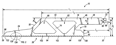
[0008] Fig. 1 illustrates a saw blade according to one embodiment of
the invention.
[0009] Fig. 2 is an enlarged view of a portion of the saw blade shown
in Fig. 1.
[0010] Fig. 3 illustrates the saw blade of Fig. 1 connected to a
reciprocating saw and
performing a footer cut.
[0011] Fig. 4 illustrates the saw blade of Fig. 1 connected to the
reciprocating saw and
performing a flush cut.
[0012] = Fig. 5 illustrates a saw blade according to another
embodiment of the invention.
[0013] Before any embodiments of the invention are explained in
detail, it is to be
understood that the invention is not limited in its application to the details
of construction and the
arrangement of components set forth in the following description or
illustrated in the following
drawings. The invention is capable of other embodiments and of being practiced
or of being
carried out in various ways.
DETAILED DESCRIPTION
[0014] Fig. 1 illustrates a saw blade 10 according to one embodiment
of the invention. The
illustrated saw blade 10 is a reciprocating saw blade for use with a power
tool such as, for
example, a reciprocating saw 14 (Figs. 3 and 4). The saw blade 10 includes a
body 18, an
attachment portion 22 for connecting the blade 10 to the reciprocating saw 14,
and a cutting
portion 26 defining a plane 30. In the illustrated embodiment, the body 18,
the attachment
portion 22, and the cutting portion 26 are integrally formed as a single piece
such that the saw
blade 10 is a unitary structure. In other embodiments, the saw blade 10 may be
formed from
several pieces that are welded or otherwise secured together.
[0015] The body 18 includes a nose portion 34, an extension portion
38, and a main body
portion 42. The body 18 also includes a back edge 46 extending between the
extension portion
38 and the main body portion 42. The nose portion 34 is relatively narrow
(i.e., short) compared
to the main body portion 42 and extends from the main body portion 42. A
leading edge 50 of
3
CA 02749666 2011-08-19
Attorney Docket No. 066042-8242-01
the main body portion 42 is oriented at an angle A1 relative to the back edge
46 to transition to
the nose portion 34. The leading edge 50 offsets the nose portion 34 from the
back edge 46. In
the illustrated embodiment, the angle Al of the leading edge 50 relative to
the back edge 46 is
approximately 45 degrees. In other embodiments, the angle A1 may be larger or
smaller.
[0016] The extension portion 38 is also relatively narrow compared
to the main body portion
42 and supports the attachment portion 22. The extension portion 38 extends
from the main
body portion 42 in a direction opposite the nose portion 34 such that the
attachment portion 22
defines a first end 54 of the body 18 and the nose portion 34 defines a second
end 58 of the body
18. The back edge 46 is generally continuous and planar between the extension
portion 38 and
the main body portion 42.
[0017] The main body portion 42 is taller than the nose portion 34
and the extension portion
38 and defines three openings 62, 66, 70. The first and second openings 62, 66
are generally the
same shape and size, but are inverted relative to one another. In the
illustrated embodiment, the
first and second openings 62, 66 are generally triangular-shaped such that the
main body portion
42 resembles a truss. A web 74 of the main body portion 42 extends between the
first opening
62 and the second opening 66 to separate the openings 62, 66. The first and
second openings 62,
66 are thereby completely bounded by the body 18. The third opening 70 is
formed as a cutout
in a trailing edge 78 of the main body portion 42. The trailing edge 78 also
defines a third end
82 of the body 18. The openings 62, 66, 70 remove material from the body 18 to
facilitate
flexing the body 18 while performing a flush cut (Fig. 4) with the saw blade
10.
[0018] The illustrated body 18 of the saw blade 10 has an overall
length Li and an overall
height H. The overall length Li is measured generally parallel to the plane 30
from the first end
54 of the body 18 to the second end 58 of the body 18. The overall height HI
is measured
generally perpendicularly from the back edge 46 of the body 18 to the plane
30. In some
embodiments, the overall length LI is between approximately 8 inches and
approximately 12
inches, and the overall height Hi is between approximately 2 inches an
approximately 2.5 inches.
In such embodiments, a ratio of the overall height Hi to the overall length Li
is between
approximately 0.17 and approximately 0.31. The relatively large overall height
H1 of the body
18 helps guide the saw blade 10 along a surface while performing a flush cut
(Fig. 4). In the
4
CA 02749666 2011-08-19
=
=
Attorney Docket No. 066042-8242-01
= illustrated embodiment, the overall length L1 is approximately 12 inches
and the overall height
H1 is approximately 2.1 inches such that the ratio of the overall height H1 to
the overall length L1
is approximately 0.18.
[0019] The overall height H1 of the saw blade 10 is maintained
through approximately 60
percent of the overall length LI of the blade 10. In the illustrated
embodiment, a distance L2
from the first end 54 of the body 18 to the point where the body 18 begins to
transition to the
nose portion 34 (i.e., the start of the leading edge 50) is approximately
7.625 inches. At the nose
portion 34, the height of the saw blade 10 is reduced to that of a
conventional reciprocating saw
blade. In other embodiments, the distance L2 from the first end 54 of the body
18 to the leading
edge 50 may be relatively longer or shorter.
[0020] The illustrated extension portion 38 has a height H2
measured generally perpendicular
to the back edge 46 of the body 18. The height I-12 of the extension portion
38 is significantly
less than the overall height I-11of the saw blade 10. In some embodiments, a
ratio of the overall
height H1 to the extension portion height H2 is between approximately 2.7 and
approximately
3.3. In the illustrated embodiment, the extension portion height H2 is
approximately 0.75 inches
and the ratio is approximately 2.8. In other embodiments, the extension
portion height 112 may
be relatively larger or smaller.
[0021] The attachment portion 22 extends from the body 18 and
includes a tang 86 and an
aperture 90. The tang 86 and the aperture 90 are configured to engage a blade
clamp of a
reciprocating saw to securely and releasably connect the blade 10 to the saw.
In the illustrated
embodiment, the attachment portion 22 extends from the body 18 at a zero
degree tang angle
(i.e., the attachment portion 22 extends generally parallel to the plane 30).
In other
embodiments, the attachment portion 22 may extend from the body 18 at an
oblique angle such
that the saw blade 10 reciprocates at an angle relative to a reciprocating
saw.
[0022] The attachment portion 22 has a height H3 measured generally
perpendicular to the
plane 30. Similar to the extension portion 38, the height H3 of the attachment
portion 22 is
significantly less than the overall height H1 of the body 18. In some
embodiments, a ratio of the
overall height Hi to the attachment portion height H3 is between approximately
4 and
approximately 5. In the illustrated embodiment, the height H3 of the
attachment portion 22 is
CA 02749666 2011-08-19
Attorney Docket No. 066042-8242-01
approximately 0.5 inches and the ratio of the overall height H1 to the
attachment portion height
H3 is approximately 4.2. In other embodiments, the attachment portion height I-
I3 may be
relatively larger or smaller.
100231 The attachment portion 22 is offset from the plane 30 and
from the third end 82 of the
body 18 to facilitate performing a footer cut (Fig. 3) with the saw blade 10.
In particular, the
attachment portion 22 is spaced a first offset distance 114, measured
generally perpendicular to
the plane 30, from the plane 30. The attachment portion 22 is also spaced a
second offset
distance L3, measured generally parallel to the plane 30, from the third end
82 of the body 18.
The first and second offset distances H4, L3 provide clearance between the
attachment portion 22
and the cutting portion 26 to reduce interference from a connected
reciprocating saw while
performing cuts in constricted areas. In some embodiments, a ratio of the
first offset distance H4
to the overall height Hi of the saw blade 10 is between approximately 0.6 and
approximately 0.8,
and a ratio of the second offset distance L3 to the overall length Li of the
saw blade 10 is
between approximately 0.2 and approximately 0.4. In the illustrated
embodiment, the first offset
distance H4 is approximately 1.5 inches and the second offset distance L3 is
approximately 2.8
inches. In other embodiments, the first and second offset H4, L3 distances may
be larger or
smaller.
[0024] The cutting portion 26 extends from the second end 58 of the
body 18 to the third end
82 of the body 18. The cutting portion 26 includes a plurality of cutting
teeth 94 and a tip
portion 98. The cutting teeth 94 are generally similarly shaped and sized to
define a tooth form
along the body 18. The cutting teeth 94 are separated by a plurality of
gullets 102. As shown in
Fig. 2, each cutting tooth 94 includes a tip 106, a rake face 110, and a
relief face 114. The tips
106 of the cutting teeth 94 define the plane 30 of the cutting portion 26.
Each cutting tooth 94
has a height H5 measured generally perpendicular to the plane 30 from a base
118 of a
corresponding gullet 102 to the plane 30. In the illustrated embodiment, the
height 115 of each
tooth 94 is approximately 0.1 inches. In other embodiments, the height H5 of
the teeth 94 may
be relatively larger or smaller or may vary along the cutting portion 26.
[0025] Referring back to Fig. 1, the tip portion 98 is formed on
the nose portion 34 of the
body 18 at the second end 58. The illustrated tip portion 98 is a plunge point
including an
6
CA 02749666 2011-08-19
Attorney Docket No. 066042-8242-01
enlarged first gullet 122 for initiating a plunge cut with the saw blade 10.
In other embodiments,
the cutting portion 26 may include different tip configurations for initiating
a plunge cut. In still
other embodiments, the tip portion 98 may simply define an end of the tooth
form and may not
be specifically configured for performing a plunge cut.
100261 The illustrated cutting portion 26 also includes two floor guard
teeth 126, 130
extending from the body 18. In other embodiments, the cutting portion 26 may
include fewer or
more floor guard teeth, or the floor guard teeth may be omitted. The first
floor guard tooth 126
is positioned toward the second end 58 of the body 18 between two cutting
teeth 94. The
illustrated first floor guard tooth 126 is spaced apart from the second end 58
such that the first
floor guard tooth 126 does not interfere with plunge cuts. The second floor
guard tooth 130 is
positioned at the third end 82 of the body 18 adjacent a single cutting tooth
94. The first and
second floor guard teeth 126, 130 are spaced apart from each other to minimize
interference
when cutting through a board. The first floor guard tooth 126 is positioned
far enough away
from the second floor guard tooth 130 such that the teeth 126, 130 remain on
opposite sides of
and do not contact the board as the saw blade 10 is reciprocated. For example,
in some
embodiments, the floor guard teeth 126, 130 may be spaced at least 6.5 inches
apart from each
other to cut through a 2x6 board. In the illustrated embodiment, the first
floor guard tooth 126 is
spaced approximately 7.25 inches apart from the second floor guard tooth 130.
In other
embodiments, the floor guard teeth 126, 130 may be spaced closer to or further
from each other
to cut through 2x4, 2x8, or 2x10 boards.
100271 The illustrated floor guard teeth 126, 130 are spaced apart from the
cutting teeth 94
by one of the gullets 102. In other embodiments, the floor guard teeth 126,
130 may be spaced
further apart from the cutting teeth 94 such that a larger gullet or dead
space is present between
the floor guard teeth 126, 130 and the cutting teeth 94. Each floor guard
tooth 126, 130 is
generally rounded and includes a relatively flat contact surface 134, 138. The
contact surfaces
134, 138 are generally parallel to the plane 30. The contact surfaces 134, 138
of the floor guard
teeth 126, 130 contact a floor or other surface while performing a footer cut
(Fig. 3) with the saw
blade 10 to inhibit the cutting teeth 94 from contacting the floor surface.
7
CA 02749666 2011-08-19
Attorney Docket No. 066042-8242-01
[00281 Each floor guard tooth 126, 130 is generally longer than
each cutting tooth 94. In the
illustrated embodiment, the floor guard teeth 126, 130 are at least twice as
long as each cutting
tooth 94. In particular, a length L4 of the illustrated first floor guard
tooth 126 (Fig. 2) is
approximately equal to the length of two adjacent cutting teeth 94, including
the gullet 102
positioned therebetween. A length of the illustrated second floor guard tooth
130 is
approximately equal to the length of two adjacent cutting teeth 94, but
without a gullet
positioned therebetween. In other embodiments, the floor guard teeth 126, 130
may be relatively
longer or shorter.
100291 As shown in Fig. 2, the floor guard teeth 126, 130 are also
generally taller than the
cutting teeth 94 such that the floor guard teeth 126, 130 extend from the body
18 beyond the
plane 30. The first floor guard tooth has a height H6 measured generally
perpendicular to the
plane 30 from the base 118 of a corresponding gullet 102 to the contact
surface 134. In some
embodiments, a ratio of the floor guard tooth height H6 to the cutting tooth
height H5 is
approximately 1.1. In the illustrated embodiment, the floor guard tooth height
H6 is
approximately 0.11 inches such that the first floor guard tooth 126 extends
approximately 0.01
inches beyond the plane 30. Although only the first floor guard tooth 126 is
shown in Fig. 2, the
second floor guard tooth 130 has approximately the same height as the first
floor guard tooth 126
and extends beyond the plane 30 approximately the same distance. In other
embodiments, the
first and second floor guard teeth 126, 130 may have different heights.
[0030] In some embodiments, the cutting teeth 94 are set relative
to the body 18 of the saw
blade 10. In the illustrated embodiment, the cutting teeth 94 between the
second end 58 of the
body 18 and the first floor guard tooth 126 are unset. Leaving these teeth 94
unset facilitates
making straight and smooth cuts with the saw blade 10 along the side of, for
example, a window
framing board. The unset teeth 94 allow the nose portion 32 of the saw blade
10 to lay flush
against a framing board to minimize damage to the board while cutting. At
least some of the
cutting teeth 94 between the first and second floor guard teeth 126, 130 are
set. For example, the
cutting teeth 94 between the floor guard teeth 126, 130 may be arranged such
that one tooth is set
in a first direction, the first subsequent tooth is set in a second direction,
the second subsequent
tooth is set in the first direction, the third subsequent tooth is set in the
second direction, and the
fourth subsequent tooth is unset. This pattern is repeated along the cutting
portion 26. In the
8
CA 02749666 2011-08-19
Attorney Docket No. 066042-8242-01
illustrated embodiment, all of the cutting teeth 94 immediately adjacent the
first and second floor
guard teeth 126, 130 are unset. In other embodiments, the cutting teeth 94 may
be set in other
patterns along the tooth form.
[0031] Fig. 3 illustrates the saw blade 10 performing a footer cut. During
a footer cut, the
saw blade 10 is used to cut a board 142, or other piece of material, that is
directly adjacent a floor
surface 146. The attachment portion 22 is inserted into the reciprocating saw
14 to connect the
saw blade 10 to the saw 14. Since the attachment portion 22 is offset
vertically and horizontally
from the cutting portion 26 as described above, the reciprocating saw 14 is
likewise offset from
the cutting portion 26. The offset reduces, or even eliminates, interference
of the reciprocating
saw 14 with the floor surface 146 as the saw blade 10 cuts through the board
142.
[0032] In addition, as the saw blade 10 completes the cut through the board
142, the cutting
teeth 94 would normally contact the floor surface 146 (which may be made of,
for example,
concrete), possibly breaking, dulling, or otherwise damaging the teeth 94.
Since the floor guard
teeth 126, 130 extend further from the body 18 than the cutting teeth 94, the
floor guard teeth
126, 130 contact the floor surface 146 and inhibit the cutting teeth 94 from
contacting the floor
surface 146. The floor guard teeth 126, 130 also help protect relatively
softer surfaces (e.g.,
wood floors) by inhibiting the cutting teeth 94 from contacting and cutting
into the soft surfaces.
Providing at least two spaced apart floor guard teeth 126, 130 creates two
points of contact
between the saw blade 10 and the floor surface 146 to reduce the possibility
of the saw blade 10
tilting relative to the floor surface 146 while performing the cut. In
addition, providing the
attachment portion 22 at the zero degree tang angle makes the saw blade 10
come down
generally perpendicular to the floor surface 146 such that both floor guard
teeth 126, 130 contact
the surface 146 at the same time.
[0033] Fig. 4 illustrates the saw blade 10 performing a flush cut. During a
flush cut, the saw
blade 10 is used to cut a board or work piece 150 that is directly adjacent a
relatively flat surface,
such as a floor surface 154. Such cuts are typically difficult to perform so
close to the floor
surface 154 because the relatively wide reciprocating saw 14 contacts the
floor surface 154 and
prevents a conventional saw blade from cutting directly against the surface
154. The openings
62, 66, 70 of the illustrated saw blade 10 facilitate performing the flush cut
by reducing the
9
¨
_______________________________________________________________________________
______
CA 02749666 2011-08-19
Attorney Docket No. 066042-8242-01
stiffness of the saw blade 10 along its length. In particular, the openings
62, 66, 70 facilitate
flexing or bending of the body 18 of the saw blade 10. In addition, the
relatively large overall
height H1 of the saw blade 10 increases tracking of the blade 10 along the
floor surface 154 to
facilitate cutting in a straight line. The large overall height 111 also
reduces the possibility of the
saw blade 10 "walking" into and damaging a framing board when performing a
flush cut along
the framing board.
[0034] Fig. 5 illustrates a saw blade 210 according to another
embodiment of the invention.
The illustrated saw blade 210 is similar to the saw blade 10 discussed above.
Differences
between the saw blades 10, 210 are discussed in detail below.
[0035] The saw blade 210 is a reciprocating saw blade and includes
a body 214, an
attachment portion 218, and a cutting portion 222. The body 214 includes a
relatively short nose
portion 226 compared to the nose portion 34 of the saw blade 10 shown in Fig.
1. The overall
height of the illustrated saw blade 210 is thereby maintained through a larger
percentage of its
overall length.
100361 The body 214 also defines three openings 230, 234, 238 to
increase the flexibility of
the saw blade 210. In the illustrated embodiment, the first opening 230 is
considerably larger
than the second opening 234. In addition, the first opening 230 is bounded on
four sides such
that the first opening 230 is a quadrilateral, while the second opening 234 is
bounded on three
sides such that the second opening 234 is a triangle. Similar to the third
opening 70 discussed
above, the illustrated third opening 238 is formed as a cutout in a trailing
edge 242 of the body.
[0037] The cutting portion 222 includes a plurality of cutting
teeth 246 and two floor guard
teeth 250, 254. In the illustrated embodiment, the first floor guard tooth 250
is spaced from a
second end 258 of the body 214 and positioned between two cutting teeth 246.
The second floor
guard tooth 254 is spaced from a third end 262 of the body 214 and also
positioned between two
cutting teeth 246. The floor guard teeth 250, 254 extend from the body 214
further than the
cutting teeth 246 to inhibit the cutting teeth 246 from contacting a floor
surface while performing
a footer cut.
CA 02749666 2011-08-19
= Attorney Docket No. 066042-8242-01
100381 Although the invention has been described in detail with
reference to certain preferred
embodiments, variations and modifications exist within the scope and spirit of
one or more
independent aspects of the invention. Various features and advantages of the
invention are set
forth in the following claims.
11
, __________________________________________