Note: Descriptions are shown in the official language in which they were submitted.
CA 02749885 2011-07-15
- 1 -
Reuse protection for lancet system
Field of the invention
The invention concerns a lancet system in the form of a lancet magazine which
can
be used in a lancing aid for collecting blood for diagnostic purposes.
In a variety of diseases it is necessary to examine human blood for an analyte
contained therein. In many cases this only requires the withdrawal of a small
amount of blood from the body in the form of a blood drop by producing a small
puncture wound. A particularly important example of such a case is diabetes in
which the glucose content of blood has to be examined at regular intervals.
Blood
may also for example be examined with regard to coagulation parameters,
triglycerides, HbAl c or lactate. Blood lancet devices which consist of a
lancing
device and tailor-made replaceable lancets are usually used to produce the
required
puncture wounds. A lancet holder in which one interchangeable lancet can be
inserted is present in the housing of the lancing device. During the lancing
operation
the lancet holder is rapidly moved in a lancing direction by a lancet drive
which is
also integrated into the lancing device until the lancet tip emerges from an
exit
opening provided at the front end of the lancing device and produces a small
puncture wound in the part of the body that is pressed against the front end.
Afterwards the lancet holder containing the lancet is moved back in the
opposite
direction to the lancing.
Small, easy-to-handle blood collection devices, so-called lancing aids that
can be
easily and reliably operated by the user and enable a part of the body to be
lanced in
a manner that is as pain-free as possible are now routinely used. In order to
avoid
infections especially in hospitals, the lancets are disposable elements
intended for
single use. After a lancet has been used once, the lancet is removed after the
lancing
CA 02749885 2011-07-15
- 2 -
operation or ejected from the device and discarded as refuse. In such a case
the
exposed lancets in a refuse container may lead to injury during waste disposal
which
may result in a contamination of other persons by the used lancet. Such
contamination may lead to infections and thus some countries are planning to
impose a ban on blood collection systems in which the needle tip is freely
accessible
after use. In addition to a risk of injury during waste disposal, there is
also a risk that
a used lancet may be accidentally re-used. This is particularly relevant for
hospitals
in which a lancing aid is used for several patients since such inadvertence of
the
nursing staff could lead to a patient being contaminated with the blood of a
previous
patient.
In addition to the use of blood lancet devices by medical staff, lancing aids
are also
used by laymen in the so-called home-monitoring field. This is particularly
the case
for monitoring the treatment of diabetics. Thus, it has been found in the
treatment of
diabetics that serious damage associated with diabetes such as loss of sight
can be
substantially reduced when the glucose concentration in the blood of the
diabetic is
determined frequently and up to five times daily and the insulin injection is
exactly
adjusted on the basis of these measurements. Lancing aids which enable the
diabetic
to carry out such a blood examination by himself are used for home-monitoring
in
order to carry out such frequent measurements. The resulting requirements for
a
blood lancet device are a simple handling when inserting new lancets and a
reliable
ejection of used lancets in addition to a simple handling when triggering the
lancing
operation and a relatively painless puncture. Lancet replacement should on the
one
hand be as simple as possible and, on the other hand, ensure the utmost safety
with
regard to unintentional injury of the user or other persons. Although in the
home-
monitoring field it is conceivable that a lancet, once inserted, is used
several times
for lancing by the same user, even in this case an accidental re-use of an
ejected
lancet should be prevented once the user has decided to discard the lancet.
Furthermore, other persons in particular should be reliably protected from the
discarded lancets for example during waste disposal.
CA 02749885 2011-07-15
- 3 -
In the prior art the tip of the lancet is usually surrounded by a tip cover
made of
plastic when the lancet is inserted which allows a safe handling when the
lancet is
inserted. When the lancet is inserted, the tip cover is removed to expose the
sharp
tip of the lancet for the lancing operation (U.S. 5,628,765). However, due to
the
exposed lancet tip there is a risk of accidental injury and the tip may become
damaged. The lancet is removed from the lancing aid after one or several
lancing
operations. This can either be carried out manually in which case there is a
high risk
of injury by the lancet tip or by an automatic ejection mechanism.
A blood lancet device is disclosed in the patent EP 0 565 970 in which the
lancet is
ejected from the lancet holder by means of an ejecting rod. The user can
operate the
ejecting rod by pressing a corresponding button.
Furthermore, an ejecting mechanism is described in the patent document U.S.
4,442,836 where the lancet is automatically released when the lancing aid is
retensioned so that the used lancet is discarded after each lancing operation.
Such
ejecting mechanisms require a relatively high degree of additional
engineering.
Moreover, multiple use of an already inserted lancet system is not possible
which is,
however, often desired by customers especially in the home-monitoring field.
Another major disadvantage of the described prior art is that the lancet tip
is
unprotected after the lancet has been ejected resulting in an associated risk
of injury
as described above.
In order to facilitate the safe removal of a used lancet, blood collection
systems are
also described in the prior art which ensure that the lancet tip is protected
after
ejecting the lancet. This is regarded as an essential feature especially for
elderly
users or those that are handicapped by poor sight and shaking hands as a
result of
disease.
CA 02749885 2011-07-15
- 4 -
A protection of the lancet tip is achieved in the prior art by integrating the
lancet in
a cap of the lancing aid such that the lancet and the housing cap together
form a
replaceable disposable unit. Such designs are described in the documents EP
0595148 and US 4,990,154, US 5,454,828 and US-2004-0034318. When the lancet
is ejected by the user, the housing cap is placed over the lancet tip so that
the lancet
surrounded by the cap can be subsequently discarded. Even if the lancet tip is
protected after ejection by the described mechanism, it is nevertheless
possible for a
careless user to reinsert a lancet that has already been ejected once and
carry out a
new lancing operation. Consequently the user himself has to recognize that the
lancet has already been used.
The document EP 0 630 609 discloses a mechanism which directly prevents
reinsertion and thus re-use of a lancet that has been ejected once. The
described
lancet device comprises a lancet with a lancet body which breaks when the
lancet is
ejected from the lancing aid to prevent a reinsertion of the lancet. This
prevents the
user from re-using a contaminated lancet. However, a disadvantage of the prior
art
is that the lancet tip is unprotected after the lancet has been ejected.
For individual lancets there are a wide variety of solutions for protecting a
user from
the used lancet tip. Thus, various mechanisms are described in the documents
US
5,964,731, US 7,001,364 and US 5,454,828 relating to how a protecting
mechanism
can be brought over the lancet after use so that the lancet cannot be re-used.
However, these mechanisms either have to be applied by the user himself which
limits the effectiveness of the protection from injury or the mechanism is
automatically triggered after each lancing operation by the lancing mechanism
of
the lancing aid as described in WO 2008/072414 so that the lancet can only be
used
once in an inserted state.
A protection against re-use is described in EP 1 459 683 which enables the
housing
of the lancet system to be changed after use of a lancet system in such a
manner that
CA 02749885 2015-01-16
,
,
- 5 -
it can no longer interact in a regular manner with a lancing aid. This is
achieved by a
change in the coupling site between the lancet magazine and lancing aid. In
this case
it is no longer possible to reinsert an already used magazine. This is
intended to
protect the user against re-using an already used lancet. However, a
disadvantage of
this prior art is that the coupling site of the lancing aid can be damaged
when it is
attempted to reinsert an already used magazine into the lancing aid if the
user does
not immediately recognize that the magazine no longer correctly fits the
coupling
site of the lancing aid.
The object of the invention is to provide an easy-to-handle lancet magazine
preferably for the home-monitoring field which can interact with a lancing aid
in
such a manner that the re-use of an already ejected lancet magazine is
prevented
without in doing so affecting the interaction of the lancet magazine and the
lancing
aid but at the same time ensuring at all times a protection from injury on the
lancet
tip when the lancet magazine is used. Multiple use of a lancet of a lancet
magazine
that has already been inserted once should advantageously be easily possible.
The object is achieved by a lancet magazine and a lancet system described
herein.
Preferred embodiments are also described.
The invention concerns a lancet magazine and a lancet system consisting of a
lancing aid and a lancet magazine. Furthermore, the invention concerns a
securing
system for securing the lancets in the lancet magazine or the lancet system.
CA 02749885 2015-01-16
- 5a -
In accordance with one aspect of the present invention, there is provided a
lancet
magazine for use in a lancing aid comprising: a housing with a distal and a
proximal
end having: i. at least one cavity for the storage of lancets, ii, a plurality
of lancets
each having a lancet body at the proximal end of the lancet and a lancet tip
at the
distal end of the lancet, wherein at least one lancet is aligned such that the
proximal
end of the lancet points towards the proximal end of the housing and the
distal end
of the lancet is oriented towards the distal end of the housing, and the
lancets in an
unused state are completely surrounded by the housing, an extension unit which
is
movably connected to the housing of the lancet magazine, characterized in that
the
housing can be extended by the extension unit in the direction of the distal
end of
the housing so that the lancet is prevented from emerging from the lancet
magazine,
wherein the extension unit interacts with the housing after movement in the
distal
direction relative to the lancet magazine housing in such a manner that it
cannot
again be moved manually in the proximal direction of the housing.
In accordance with another aspect of the present invention, there is provided
a lancet
system for carrying out a lancing operation in a body, comprising: a lancing
aid with
a housing and a drive mechanism for a lancet as well as a receiving opening
for a
lancet magazine, a lancet magazine described herein with a housing which has a
distal and a proximal end comprising at least one lancet, where the lancet has
a tip
at its distal end and the distal end points towards the distal end of the
lancet
magazine, an extension unit which is movably connected to the housing of the
lancet magazine, characterized in that the lancet magazine can be extended by
the
extension unit in the direction of the distal end of the housing thus
preventing the
lancets from emerging from the lancet magazine upon interaction with the
lancing
aid.
CA 02749885 2015-01-16
- 5b -
In accordance with yet another aspect of the present invention, there is
provided a
method for avoiding a reuse of a lancet magazine comprising the steps:
inserting an
unused lancet magazine containing at least one lancet described herein into a
lancing aid, removing the lancet magazine from the lancing aid, whereupon a
movable extension unit on the lancet magazine is moved towards the distal end
of
the lancet magazine.
In accordance with yet another aspect of the present invention, there is
provided a
lancet holder for securing lancets in a lancet magazine comprising: a lancing
aid
with an opening for receiving a lancet magazine, where the lancing aid has a
removal position in which a drive element can interact with one of the lancets
in the
lancet magazine in such a manner that this lancet is movably supported in the
lancet
magazine for a lancing operation, a lancet magazine described herein
containing at
least one lancet, characterized in that the lancing aid additionally has a
securing
element which prevents movement of the lancets which are not positioned in the
collecting position.
In accordance with yet another aspect of the present invention, there is
provided a
lancet magazine for use in a lancing aid that includes a lancing aid housing
with an
opening therein for receiving the lancet magazine, the lancet magazine
comprising:
a magazine housing having distal and proximal ends; a plurality of lancets
disposed
in the magazine housing, each lancet having a lancet body at a proximal end of
the
lancet and a lancet tip at a distal end of the lancet, at least one of the
lancets being
aligned relative to the magazine housing such that the proximal end of the one
lancet is oriented toward the proximal end of the magazine housing and the
distal
end of the one lancet is oriented toward the distal end of the magazine
housing,
wherein in an unused state the lancets are completely surrounded by the
housing;
and an extension unit movably connected to the magazine housing between an
unextended state and an extended state, wherein moving the extension unit to
the
extended state extends the length of the magazine housing in the direction of
the
CA 02749885 2015-01-16
- Sc -
distal end of the magazine housing, whereby the lancets are prevented from
emerging from the lancet magazine when the extension unit is in the extended
state;
and wherein the lancet magazine is configured to be insertable into a lancing
aid
after the extension unit is moved to the extended state.
In accordance with yet another aspect of the present invention, there is
provided a
lancing system, comprising: a lancing aid having a lancing aid housing with an
opening therein for receiving a lancet magazine, the lancing aid comprising a
drive
mechanism for driving a lancet in a puncture movement; and a lancet magazine
described herein removably receivable in the opening of the lancing aid
housing.
The lancet magazine for use in a lancing aid comprises a housing having a
distal and
a proximal end and at least one cavity for storing lancets. A plurality of
lancets each
having a lancet body at the proximal end of the lancet and a lancet tip at the
distal
end of the lancet which is suitable for generating an opening in the skin, are
located
in the lancet magazine. The proximal end of at least one lancet points in the
direction of the proximal end of the housing and the distal end of the lancet
is
CA 02749885 2011-07-15
- 6 -
aligned in the direction of the distal end of the housing. The proximal end of
the
lancet magazine housing is preferably designed such that it can interact with
a
lancing aid. This interaction can be characterized by the magazine holder or
by the
design of the proximal end allowing entry of a drive element of the lancing
aid e.g.
in the form of an opening or recess in the lancet magazine housing. The
lancets are
completely surrounded by the housing in the unused state. This ensures that
whenever the lancet magazine is used the user cannot be injured by the
lancets. The
lancet is only moved into a deflected state by the drive mechanism of the
lancing aid
and can puncture the skin of the user when it is in the withdrawal position.
Furthermore, the lancet magazine has an extension unit which is movably
connected
to the housing of the lancet magazine. The extension unit can move in the
direction
of the distal end of the magazine housing such that the housing can be
extended by
the extension unit in the direction of the distal end of the housing and can
thus
prevent the lancet from emerging from the lancet magazine. As a result the
lancet
does not emerge from the lancet magazine even when a lancing mechanism is
triggered and even if the lancet magazine is correctly inserted into the
lancing aid.
There is preferably a lancet in each cavity. The cavities can be separated
from one
another by cavity walls. It is, however, also conceivable that the cavity is
the void
around each lancet and that they are only separated from one another by a
groove or
notch on the lancet magazine. The cavity may also be a hollow space in which
at
least two lancets are located which are at a defined distance from one
another. After
the lancet magazine has been extended, the lancet cannot emerge from the
extended
lancet magazine housing even if the lancet magazine has been correctly coupled
with the lancing aid.
Consequently the lancet magazine has two elements which are interconnected in
such a manner that they can move relative to one another. The said elements
are the
lancet magazine housing itself and the extension unit. These two elements are
arranged relative to one another in such a manner that the lancet magazine can
be
selectively converted from an unextended state into an extended state. There
are no
CA 02749885 2011-07-15
- 7 -
constraints on the shape and design of the two elements provided they are
arranged
movably in relation to one another such that in the unextended state at least
one of
the lancets in the lancet magazine housing can be at least partially moved out
of the
lancet magazine housing and that in the extended state of the lancet magazine
the
lancet cannot emerge from the lancet magazine. During the extension process
the
extension unit is preferably moved parallel to at least one lancet in the
lancet
magazine. This is the lancet which is located in a removal position in the
lancet
magazine or lancet system. This removal position is defined relative to the
lancet
magazine such that the lancet magazine housing has an opening at the distal
end
through which the lancet can pass. In relation to a lancing aid into which the
lancet
magazine can be inserted, the removal position is characterized such that a
drive
element (e.g. a plunger) can interact with one of the lancets in the lancet
magazine
such that this lancet is movably supported in the lancet magazine for a
lancing
operation. The extension of the lancet magazine in the direction of the
longitudinal
axis of the lancet in the removal position ensures that the lancet cannot
emerge from
the lancet magazine even when it is deflected by a lancing aid.
The extension unit as well as the lancet magazine housing can be manufactured
from plastic material but other materials such as sheet metal are also
conceivable.
The lancet magazine housing preferably has a drum-like shape. Other shapes
such
as cuboid, cylindrical or disk-shaped structures are also conceivable. In this
case the
lancet magazine has at least one opening which allows at least one lancet to
emerge
from the lancet magazine housing during a lancing operation in the unextended
state
of the lancet magazine. In this process at least part of the lancet but at
least the
lancet tip protrudes from this opening. The extension unit which is movably
connected to the lancet magazine housing at least in the area of the opening
is
located around at least part of the lancet magazine housing either within or
outside
the lancet magazine housing. It can be connected by means of guide grooves.
The
extension unit is preferably located outside the lancet magazine housing and
matches the shape of the lancet magazine housing in at least two dimensions.
In this
CA 02749885 2011-07-15
- 8 -
connection the extension unit has a form fit with the lancet magazine housing.
Furthermore, the movement of the extension unit is restricted in both
directions in
the direction of movement to prevent the extension unit from unintentionally
slipping from the lancet magazine housing. This restriction can, on the one
hand, be
achieved by guide elements such as a groove and notch whose shape and lengths
are
matched to one another in such a manner that movement along one axis is
restricted.
On the other hand, the extension unit can be tapered at one end relative to
the
dimension of the lancet magazine housing so that a restriction of movement is
achieved by the tapering. Since, the aim is to be able to align or move the
extension
unit selectively relative to the lancet magazine housing such that the lancets
do not
emerge from the lancet magazine in the extended state even when they are
deflected, it should be possible to move the extension unit at least in the
direction of
the opening of the lancet magazine housing in order to prevent the lancet from
emerging from the lancet magazine in the removal position in the case of an
intentional or unintentional lancing operation. The extension unit preferably
has a
length in its dimension in the direction in which the extension takes place
which
corresponds to at least the length of the part of the lancet which comes out
of the
lancet magazine housing during a regular lancing operation. However, the
extension
unit may also be longer. However, according to the invention at least the
length of
the exiting part of the lancet should be covered by the extension unit in the
extended
state during a normal lancing operation.
Consequently the lancet magazine is rendered unusable by the movement of the
extension unit and at the same time the user is additionally protected against
unintentional puncturing because the lancets are completely surrounded by the
lancet magazine. The extension of the lancet magazine in the distal direction
ensures that the proximal side of the magazine that can interact with a
lancing aid is
not impaired. This prevents reuse of the lancet magazine after extension of
the
magazine without impairing the insertion of the magazine. This has the
advantage
that if a used lancet magazine is accidentally inserted into the lancing aid,
the
CA 02749885 2011-07-15
- 9 -
docking site between the lancet magazine and lancing aid is not impaired. This
prevents the lancing aid which should be available for many years for the
user, from
being manipulated by a modified lancet magazine so that it is made unusable as
is
the case in EP 1 459 683 in which the lancet magazine is modified at the
proximal
end of the magazine in order to achieve a reuse in the form of a protection
against
reinsertion.
The extension unit can be moved automatically when the magazine is removed
from
the lancing aid. This can for example be carried out by means of an automatic
ejection mechanism of the lancing aid which is actuated by the user once the
magazine has been consumed. However, the extension unit can also be moved
manually by the user along the lancet magazine when he manually removes the
magazine from the lancing aid. In this case the lancet magazine housing and
the
extension unit are connected together in the unextended state such that the
extension
unit can only be transferred into the extended state when a certain
application of
force has been exceeded. This can for example be achieved by means of the fact
that
parts of the lancet magazine housing and of the extension unit are so closely
mounted together that a certain frictional force has to be overcome until it
is
possible to move the extension unit. This securing of the unextended state can
alternatively be accomplished by elements on the lancet magazine housing and
extension unit such as for example notches or projections which rub against
one
another or hook into each other or lock into each other. A similar locking
also takes
place in the extended state of the lancet magazine.
In a preferred embodiment the magazine can be inserted into the lancing aid in
such
a manner that the user can also remove the magazine without actuating the
extension mechanism. This enables the user to also remove a lancet magazine
from
the lancing aid which has not been completely used up without it being made
unusable by the extension. This can be achieved either by means of the fact
that the
extension unit extends within the lancet magazine housing and only protrudes
from
CA 02749885 2011-07-15
- 10 -
the distal end of the lancet magazine housing and can then be gripped in order
to
carry out the extension process. In an alternative embodiment the lancet
magazine
housing can be stretched out such that it is mounted in the inserted state
within a
lancing aid in such a manner that it can be gripped by the user so that the
user is not
able to handle the extension unit in order to remove the lancet magazine from
the
lancing aid and thus trigger the extension mechanism but can rather grip the
lancet
magazine housing itself and remove the lancet magazine without using the
extension mechanism.
Furthermore, it is possible to use the lancet which is located in the
collecting
position in the lancet system several times. Hence, the user can select how
often he
uses each lancet before he moves a new lancet into the collecting position
e.g. by
advancing the magazine in the lancing aid. However, the extension process can
also
be carried out on the lancet magazine without the magazine being inserted into
the
lancing aid.
The lancet magazine can also be inserted at any time into the lancing aid even
in the
extended state. In this case the proximal end of the lancet magazine housing
can be
inserted into the lancing aid to enable a correct interaction between the
lancing aid
and magazine. The lancing operation as such in which the drive unit interacts
with
the lancet and moves the lancet within the lancing aid can be also executed
without,
however, the lancet emerging from the lancet magazine.
The extension unit preferably interacts with the housing after it has moved in
the
distal direction relative to the housing of the lancet magazine i.e. in the
extended
state so that it cannot again be manually moved in the proximal direction of
the
housing. This is preferably achieved by a locking between the extension unit
and
lancet magazine housing. Interaction of two notches or of a groove and notch,
one
on the extension unit and one on the lancet magazine housing, are examples of
such
CA 02749885 2011-07-15
- 11 -
a locking of the two elements. This prevents the extension unit from moving
again
by itself into its original length in the unextended state.
The invention additionally concerns a lancet system for carrying out a lancing
operation in a body comprising a lancing aid with a housing and a drive
mechanism
for a lancet as well as a receiving opening for a lancet magazine, a lancet
magazine
with a housing, which has a distal and a proximal end, comprising at least one
lancet, the lancet having a tip at its distal end and its distal end pointing
in the
direction of the distal end of the lancet magazine, an extension unit which is
movably connected to the housing of the lancet magazine.
The lancet magazine can be extended by the extension unit in the direction of
the
distal end of the housing thus preventing the lancets from emerging from the
lancet
magazine when it interacts with the lancing aid. In this process the proximal
end of
the lancet magazine is inserted into the lancing aid because the proximal end
of the
magazine is preferably designed so that it can interact with the lancing aid
in such a
way that it is held.
An important aspect of the invention is a lancet magazine that can be removed
from
the drive unit and which contains at least one lancet, the lancet magazine
being
provided as a disposable unit. In this connection the term lancet encompasses
a
blade-shaped, flat lancing unit as well as other conceivable embodiments. In
principle lancets as they are basically well-known in the prior art and are
used in
lancet systems can be used within the scope of the invention. In this
connection a
combination of a lancet with a base body which can couple to the lancing aid
is
frequently referred to as a lancet in the prior art. Such lancets often have a
base body
made of plastic in which a metal lancet is disposed. According to the
invention it is
possible to integrate such a lancet into the lancet magazine or system
according to
the invention. It is for example conceivable that the lancet body according to
the
invention contains a base body like that used for lancets in the prior art,
where the
CA 02749885 2011-07-15
- 12 -
inventive functionality of the system is maintained by integration of the base
body.
In this case the lancet body has an at least two-part design according to the
described embodiment. The lancet and the base body can then be guided in a
movable manner within the magazine. The lancets within the lancet magazine are
preferably present in separate cavities in order to prevent contamination of
unused
lancets by used lancets when reloading.
In order to carry out a lancing operation, portions of the lancet body are
advantageously designed like the system already described in DE 10053974 such
that the individual lancets of the system can be actively coupled to the drive
unit of
the lancing aid. Embodiments that can also be used to drive lancets within a
magazine of a lancing aid are described for example in the documents DE
10053974, U.S. 4,990,154 and U.S. 5,074,872. The chambers arranged next to one
another in which the lancets are individually located are positioned
successively
relative to the drive unit in order to carry out a lancing operation in such a
manner
that in each case a single lancet can be coupled to the plunger of the drive
unit. Also
in this case magazines in the form of a drum containing chambers in which the
lancets are located parallel to the longitudinal axis of the drum have also
proven to
be particularly advantageous. The lancets preferably have additional lancet
body
arms on their lancet body which can interact with the drive unit of the
lancing aid in
such a manner that a form-fitting connection can take place between the drive
unit
(e.g. in the form of a plunger) and the lancet so that a guided movement of
the
lancet can take place during the lancing operation.
The lancet system can comprise a lancing aid with an attachable cap which can
be
removably connected to the housing of the lancing aid. After the extension
operation of the lancet magazine by movement of the extension unit relative to
the
lancet magazine housing in which the extension unit is moved in the direction
of the
distal end of the housing of the lancet magazine, the cap can no longer be
properly
connected to the housing of the lancing aid. This is a further indication for
the user
CA 02749885 2011-07-15
- 13 -
of the lancing aid that the lancet magazine that he wants to use in the
lancing aid has
already been used.
In addition a method for avoiding reuse of a lancet magazine is described in
which
the unused lancet magazine containing at least one lancet is placed in a
lancing aid
where the lancet magazine can again be removed from the lancing aid and a
movable extension unit on the lancet magazine is moved in the direction of the
distal end of the lancet magazine.
The lancets in the lancet magazine can be secured by securing means against a
movement relative to the lancet magazine housing caused by accidental
application
of force. Such an accidental application of force can for example be that the
lancet
magazine alone is dropped or is dropped in combination with a lancing aid in
which
the lancet magazine is fitted.
This securing means can for example be a plastic sheath around the lancet tip.
This
sheath can be pierced when sufficient force is exerted on the lancet by a
lancing aid.
This sufficient exertion of force occurs for example during a normal lancing
operation in which the drive unit of the lancing aid e.g. in the form of a
plunger, is
moved onto the lancet and the tip of the lancet is driven out of the housing
of the
lancing aid by this force impact in a guided movement. In contrast, the force
exerted
when a lancet magazine drops from a height of for example 2 m is not
sufficient to
pierce the plastic material. The threshold at which the force exerted is
sufficient to
pierce the plastic can be influenced by the selection of the composition of
the
plastic. US 2003-0153939 describes how such a plastic can be constructed and
how
it can be connected to the lancet in such a manner that it fulfils the
function of a
sterile protection as well as a means for securing the lancet in the case of a
fall.
In addition the lancet system can also have a lancet holder for securing
lancets in a
lancet magazine in which case the lancing aid has a cavity for receiving a
lancet
CA 02749885 2011-07-15
- 14 -
magazine, and the lancing aid has a removal position in which a drive element
can
interact with one of the lancets in the lancet magazine such that this lancet
is
movably supported in the lancet magazine for a lancing operation. In this
connection the lancing aid additionally has a securing element which prevents
movement of the lancets which are not positioned in the collecting position.
This
securing element is preferably designed in the form of a pin which at least
partly
penetrates into the lancet magazine when the lancet magazine is inserted into
the
lancing aid. When the lancet magazine is inserted into the lancing aid, this
pin is
positioned relative to the lancet magazine in such a manner that the lancet
body
arms of the lancets which are not in the collecting position are secured in a
recess of
the lancet magazine housing. The lancet which is in the collecting position is
for
example secured by the plunger of the drive unit of the lancing aid by means
of the
fact that the lancet body arms and the plunger make a form-fit. The pin
preferably
has an elongate pen shape and thus advantageously has a round shape. Due to
the
round shape it creates less resistance when the lancet magazine is inserted
into the
lancing aid. The selective securing of only the lancets that are not in the
collecting
position is for example accomplished in that the pin is at least partly
asymmetrically
inserted into the lancet magazine. Alternatively the pin can have a recess for
the
drive element of the lancing aid which is moved parallel to the pin in the
housing of
the lancing aid during the lancing operation. This securing means protects the
lancets in the lancet system or in the lancet magazine from unintentional
displacement. An unintentional displacement of the lancets would for example
be
that the lancing aid together with the lancet magazine is dropped. Falls from
greater
heights e.g. from up to heights of 3 m can be absorbed by this mechanism
without
the risk that a lancet accidentally emerges from the lancing aid or the lancet
magazine. As a result the risk of injury due to incorrect operation of the
lancing aid
is largely eliminated.
An important requirement for the lancet system is the sterility of the lancet
tip
which is provided to produce a wound in an appropriate part of the body. The
CA 02749885 2011-07-15
- 15 -
sterility of the lancet tip has to be ensured over a long period which extends
from
the manufacture of the lancet system up to its use. Sterility can be achieved
during
the manufacture of the lancet system by for example gamma radiation which is
commonly used in the prior art. In order to maintain sterility, the lancet
system can
be sealed in a wrapping for example a polyethylene bag. In another embodiment
the
opening of the lancet system where the lancet tip emerges from the protective
portion of the lancet body can for example be closed by a sealing foil. These
are
preferably detachable sealing foils which the user removes before using the
lancet
system. However, it is also possible to use thin foils which are not pierced
by the
lancet tip until the lancet is used so that the user does not have to carry
out
additional handling steps. Such foils may already be used as an integral part
of the
manufacturing process for the lancet system which is usually by means of an
injection moulding process.
Furthermore, in the prior art an elastomer is described in the application WO
01/66010 for sterile protection which encloses the lancet tip and thus
protects it
against contamination. This sterile protection can either be pierced during
the
lancing operation or be removed by the operator before use.
In an advantageous embodiment the protective portion of the lancet body can
comprise a sterile protection and/or the protective portion can be essentially
formed
thereby. In this case the elastomer of the sterile protection itself serves
for example
as the protective portion of the lancet body by the fact that the lancet tip
can be
moved in a guided manner relative to the elastomer. In this process the
sterile
protection reversibly exposes the lancet tip or surrounds it again as for
example in
the case of an elastomer protection (US 2003-0153939) in which the elastomer
is
firstly pierced during the lancing operation and subsequently the lancet tip
is
retracted into the elastomer. Consequently in this example the lancet tip
changes its
position relative to the sterile protection during the lancing operation and
the lancet
tip is protected in its resting position after the lancing operation. In
principle many
CA 02749885 2011-07-15
- 16 -
embodiments of a sterile protection are conceivable and hence the inventive
system
is not limited to any special embodiment of a sterile protection.
Description of the figures
Fig. la: Side view of a lancet magazine with an extension unit in the
unextended
state.
Fig. lb: Side view of a lancet magazine with an extension unit in the
extended
state.
Fig. 2a: View of the lancet magazine from fig. la in a longitudinal
section along
a line of intersection B-B.
Fig. 2b: View of the extended lancet magazine from fig. lb in a
longitudinal
section along the line of intersection B-B.
Fig. 3a: View of the lancet magazine from fig. 2a along a line of
intersection A-A.
Fig. 3b: View of the lancet magazine from fig. 2b in a longitudinal
section along
the line of intersection A-A from fig. 2b.
Fig. 4a: View of a lancet magazine fitted into a lancing aid which has a
removable protective cap in a non-extended state in a longitudinal
section along the line of intersection A-A.
Fig. 4b: Longitudinal section along the line of intersection A-A of a
lancet
magazine in an extended state fitted into a lancing aid with a removable
protective cap where the protective cap no longer latch with the lancing
aid.
CA 02749885 2011-07-15
- 17 -
Fig. 5a: Side view of a lancing aid with a finger cap which is correctly
locked
into place because the inserted lancet magazine is not in an extended
state.
Fig. 5b: Longitudinal section through a lancing aid from fig. 5a with a
finger cap
and inserted lancet magazine in a non-extended state along the line of
intersection A-A.
Fig. 5c: Longitudinal section of a lancing aid with an inserted lancet
magazine
after extension and attached finger cap which cannot be correctly locked
with the lancing aid (line of intersection A-A).
Fig. 5d: Side view of a lancing aid with a finger cap which cannot latch
with the
lancing aid because the lancet magazine is in an extended state.
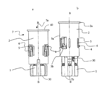
The lancet magazine (7) shown in figures 1 to 5 has a cylindrical shape which,
however, does not mean that the magazine cannot also have any other shape,
such as
for example a box-like or cuboid shape. The cylindrical shape of the lancet
magazine (7) shown here enables the lancets to be stored in the longitudinal
direction of the cylindrical housing (1). Hence, the lancets lie parallel to
one another
in the housing (1).
Figure la shows a lancet magazine (7) with a housing (1) which completely
encloses the stored lancets (not shown here). The lancet magazine (7) has an
opening (30) at one end (the proximal end) through which a lancing aid (not
shown
here) can interact with the lancets in the inside of the lancet magazine (7).
There is
likewise at least one opening (40) on the opposite side (the distal end) of
the lancet
magazine (7) which enables a lancet to exit from the magazine (7) during the
lancing operation. The lancet magazine (7) additionally has an extension unit
(2)
which is movably connected to the housing (1). This extension unit (2)
preferably
also has a cylindrical design and is longitudinally aligned parallel to the
housing of
CA 02749885 2011-07-15
- 18 -
the lancet magazine (2) where at least part of this extension unit movably
interacts
with the housing (1). In the special embodiment of figures 1 and 2 the
extension unit
(2) spans a part of the lancet magazine housing (1) in its longitudinal
extension and
protrudes from the lancet magazine housing (1) at the distal end of the lancet
magazine housing (1). This distal end of the extension unit (2) has a handle
edge
(2a) which is in the form of a thickening of the cross-section of the
extension unit
(2). Furthermore, the extension unit (2) has at least one lateral slot (5) and
at least
one guide (6) on its longitudinal side. The side slot (5) serves to receive a
latch arm
(4) which is attached to the lancet magazine housing (1). The latch arm (4)
moves
during the process of extending the lancet magazine housing (1) through the
extension unit (2) from the distal end of the side slot (5a) to the proximal
end of the
side slot (5b) so that the latch arm (4) prevents the extension unit (2) from
being
moved further beyond the lancet magazine housing (1). Hence, it limits the
extension displacement so that the extension unit (2) cannot be completely
removed
from the lancet magazine housing (1). Consequently the latch arm (4) can be
seen at
the upper (distal) end of the side slot (5a) in fig. la, whereas after
extension of the
lancet magazine (7) it is found in fig. lb at the proximal end of the side
slot (5b).
Furthermore, the extended lancet magazine (1) from fig. lb has an optical mark
(50)
in the form of letters. This optical mark (50) can, however, also be designed
in the
form of a coloured mark preferably on the lancet magazine housing (1).
A cross-section of the lancet magazine (7) from figure la is shown in figure
2a in
the line of intersection B-B. This view shows the arrangement of the latch arm
(4)
within the lancet magazine housing (1) where one end of the latch arm
protrudes out
of the side slot (5) of the extension unit (2). An additional latch arm (4a)
is attached
to another position of the lancet magazine housing (1) and is arranged within
the
extension unit (2). This latch arm (4a) has a notch (4b) which can interact
with the
notch (2b) of the extension unit (2) during an extension operation of the
lancet
magazine housing (1) in such a manner that the lancet magazine housing (1) can
no
longer be shortened as shown in figure 2b. In this case this is achieved by
bevelling
CA 02749885 2011-07-15
- 19 -
the notches (4b) and (2b) in opposite directions so that these two elements
are
locked together in a form-fitting manner. The magazine housing (1) and
extension
unit (2) can also interact in other ways to prevent a return movement after
the
extension phase. Thus, it would also be conceivable that the notch (4b)
engages in a
groove of the extension unit (2) and is locked into position there. During the
extension process, the inner latch arm (4a) is pressed by the notch (2b) into
the
inside of the lancet magazine until the notch (5b) has slid past the notch
(4b). When
the two notches slide past each other a certain frictional resistance is built
up which
has to be overcome during the extension process. This ensures that the lancet
magazine (7) does not become extended by itself or by a small exertion of
force in
its longitudinal direction by moving the extension unit (2) against the lancet
magazine housing. Although the inserted lancets (8) cannot be completely seen
in
this view of figures 2a and 2b because they are covered by a cavity boundary
(3a), it
is at least possible to see the lancet body arms (8c) of two lancets (8) below
the
cavity boundaries (3a).
Figure 3a shows the stored lancets (8) with the lancet tips (8a) as well as
the lancet
bodies (8b) and the lancet body arms (8c) in the sectional plane A-A of figure
2a. In
addition a sterile protection (9) which surrounds at least the lancet tip (8a)
is shown
in this sectional view. This sterile protection (9) serves to keep the lancet
tip (8a)
sterile during the storage phase and can be held back by the lancet opening
(40)
during the drive operation of the lancet (8) wherein a plunger of the lancing
aid can
interact with the lancet body arm (8c) and move the lancet (8) towards the
opening
(40) of the lancet magazine so that the lancet tip (8) is exposed for the
lancing
operation. This sterile protection (9) can additionally undertake the function
of
securing the lancets (8) in the lancet magazine (7) while the lancet magazine
(7) is
in use i.e. is inserted into a lancing aid but also outside a lancing aid. In
this
connection the sterile protection (9) secures the lancets (8) against
unintentional
protrusion from the openings (40) when a small force is exerted e.g. by
dropping the
lancet magazine (7).
CA 02749885 2011-07-15
- 20 -
Figure 3b shows the lancet magazine (7) after the extension process where the
lancet tip (8a) of the lancet (8) at maximum excursion does not project from
the
lancet magazine (7). The maximum excursion is for example reached during the
regular drive of the lancet (8) in a lancing aid (not shown here) as is
carried out for a
common lancing process in order to puncture the skin of a patient for blood
collection.
This state is shown in fig. 4b in which the lancet magazine (7) is present
integrated
into a lancing aid (15) after the lancet magazine housing (1) has been
extended. In
this case it is indeed possible to correctly couple the lancet magazine (7) to
the
lancing aid (15) which means that the means for locking together the lancet
magazine (7) and lancing aid (15) are not impaired. It is also still possible
to couple
the plunger (11) so that the lancet (8) is moved within the lancet housing (1)
to the
distal end of the lancet magazine (7a) but cannot emerge from the lancet
magazine
(7) that has been extended by the extension unit (2) and consequently no
lancing
operation can be executed. However, in this embodiment it is not possible to
attach
the finger cap (20) in such a manner that the housing of the lancing aid (10)
can lock
with the finger cap (20).
This is different in the non-extended state of the lancet magazine (7) which
is
correctly incorporated into a lancing aid (15) as shown in fig. 4a. In this
case the
lancet magazine (7) is also inserted and centred in the lancing aid (15) by
means of a
pin (12) so that the plunger (11) can interact in a lancing operation with the
lancet
(8) via the lancet body arm (8c) in such a manner that the lancet (8) in the
magazine
is moved in a guided manner and the lancet tip (8a) is moved out of the
lancing aid
(15) through the opening (21) of the finger cap (20). In this case the pin
(12) is
inserted in such an asymmetric manner into the lancet magazine (7) that it
does not
impede the movement of the plunger (11) with the lancet (8) that is currently
located in front of the opening of the finger cap (21), but protects all other
lancets
(8) in the magazine against unintentional movement. This movement protection
is
CA 02749885 2011-07-15
- 21 -
achieved in that the lancet body arms (8c) of the other lancets (8) are
located in a
groove (13) of the lancet magazine (1) (or alternatively between the lancet
magazine
(1) and lancing aid (15)). The pin projects beyond a part of the lancet body
arms
(8c) to such an extent that even when force is exerted on the lancing aid (15)
or onto
the lancet magazine (7), the lancets (8) cannot shift from their position
because the
lancet body arm (8a) is clamped in the groove (13) between the pin (12) and
the
lancet magazine housing (1).
Figures 5a) to 5d) show the lancet magazine (7) incorporated in a lancing aid
(15)
with an attached finger cap (20) in the unextended state of the lancet
magazine (7)
in fig. 5a) and 5b) and in the extended state of the lancet magazine (7) in
figs. 5c)
and 5d). The lancing aid (15) with a properly attached finger cap (20) is
shown in
fig. 5a) where the finger cap (20) is locked with the housing (10) of the
lancing aid
(15) in such a manner that it optically forms one unit. A section along the
line of
intersection A-A of this assembled lancing aid (15) is shown in fig. 5b). This
in turn
shows that the lancet magazine (7) interacts with the lancing aid (15) in such
a
manner that the plunger (11) of the lancing aid (15) can be brought into
contact with
the lancet body arm (8c) in such a manner that the tip (8a) of the lancet (8)
can
emerge in a guided manner from the opening (21) of the lancing aid (15) or the
finger cap (20).
Fig. 5b) and Sc) show the state in which an extended lancet magazine (7) is
inserted
into a lancing aid (15) where the magazine (7) can interact with the lancing
aid (15)
but the finger cap (20) can no longer be correctly placed on the lancing aid.
This is
shown particularly well in fig. 5d) because the depression in the housing (10)
of the
lancing aid (15) is exposed and is not reached by the finger cap (20) so that
only a
loose connection between the finger cap (20) and lancing aid (15) is achieved
which
does not hold when the lancing aid (15) alone is gripped in its housing (10)
and held
in the direction of the distal end (7a). In this state it becomes apparent to
the
CA 02749885 2011-07-15
- 22 -
operator that the magazine (7) cannot be correctly assembled with the lancing
aid
(15) including the finger cap (20) and must consequently have been used.
CA 02749885 2011-07-15
- 23 -
List of reference numerals
1 housing of the lancet magazine
2 extension unit
2a grip edge
2b notch on extension unit
3 cavity
3a cavity boundary
4 latch arm
4a latch arm inside
4b notch on latch arm
5 side slot
5a distal end of side slot
5b proximal end of side slot
6 guide
7 lancet magazine
7a distal end (lancet magazine)
7b proximal end (lancet magazine)
8 lancet
8a lancet tip
CA 02749885 2011-07-15
- 24 -8b lancet body
8c lancet body arm
9 sterile protection
housing of lancing aid
5 11 plunger
12 pin
13 groove
lancing aid
finger cap
10 21 opening of finger cap
23 depression
proximal opening of lancet magazine
distal opening of lancet magazine
optical mark