Note: Descriptions are shown in the official language in which they were submitted.
CA 02749906 2013-05-01
INCLINED DISPLAY SHELVES AND ACCESSORIES THEREFOR
This invention relates to inclined display shelves and accessories
therefor which allow the better display of products for sale on display
shelves of the
inclined self feeding type..
BACKGROUND OF THE INVENTION
Racks to hold and display packaged products in the fastener industry
are known, both with horizontal and sloped or angled shelves. Shelves that are
angled downwards or toward the viewer or customer are also known, and are
designed in this manner to allow the remaining boxes or packages to slide
forward
as the first container in the row is removed by a worker or customer.
Carton flow racks of this type provide excellent storage density
combined with picking efficiency. No power source is required, and because
frontage per item is greatly reduced, restocking and picking can be done much
faster. In fact, one person can do the work of three or four. Typically static
shelving:
pickers spend only 15% of their time doing productive work. It has been found
that
with gravity carton flow, pickers spend 85% of their time doing productive
work. A
gravity carton flow system may cost a little more than conventional shelving
but it
cuts labor costs drastically. This type of racking is commonly used by
retailers such
as Home Depot and Lowes. Examples of a system which allows the gravity flow
system to be allied to conventional shelving frame work is shown in Canadian
Patent
2453273 entitled SHELVING DISPLAY RACK which corresponds to US Patent
6,799,689.
CA 02749906 2013-05-01
2
Products for shelving of this type are commonly packaged in square or
rectangular shaped boxes or containers to be place on the shelf. In some
cases,
heavily loaded boxes may bind or stick to the shelf material thus preventing
the self
feeding system form operating.
SUMMARY OF THE INVENTION
It is one object of the invention to provide an arrangement of
containers for the rack which will assist with displaying the products
contained on the
inclined shelf.
According to one aspect of the invention there is provided an
apparatus comprising:
a set of containers for use with a display rack with a planar shelf
surface which is inclined at a shelf angle from a front edge upwardly and
rearwardly
to a rear edge so that articles on the planar shelf surface tend to slide
forwardly to
the front edge, the set of containers each container comprising:
a base sitting on the planar shelf surface;
an upstanding front wall;
an upstanding rear wall;
a top wall;
and two upstanding side walls;
the containers of the set being arranged in a row with each container
immediately in front of a next container behind;
CA 02749906 2013-05-01
3
so that the rear wall of said each container is butting the front wall of
the next container behind;
and so that a forwardmost one of the containers has the front wall
thereof located at the front edge of the shelf surface;
the front and rear walls of the containers defining therebetween a
common width of the containers and the side walls of the containers defining
therebetween a common depth of the containers;
the containers having the front and rear walls thereof inclined at a wall
angle to a plane at right angles to the base so that, with the base sitting on
the
inclined planar shelf surface, the front and rear walls stand substantially
upright;
the top wall of each container being inclined to the base at an angle so
that the rear wall of said each container is of less height from the planar
shelf
surface than the front wall of said next container behind;
so that, for each container of the row, a strip portion at the top edge of
the front wall of said next container behind is exposed above the top edge of
the rear
wall of said each container;
and so that, when viewed in front elevation, the strip portion of the front
wall of each container in the row is visible.
Preferably the strip portion of the front wall of the containers of the row
contains product data printed thereon.
Preferably the strip portion of the front wall of the containers of the row
contains machine readable data printed thereon identifying the container.
CA 02749906 2013-05-01
4
Preferably the apparatus further comprises a tray with a flat base
arranged to sit on the shelf with front and rear walls upstanding from the
base, the
tray having a width substantially equal to the width of the containers for
receiving
one row of the containers.
Preferably the tray includes a removable cover portion for retaining the
containers on the tray and protecting the containers for shipping, the cover
portion
being removable to allow the tray containing the containers to be placed on
the shelf
for display of the containers.
Preferably the tray has at least the base thereof formed from a plastics
'10 material having a coefficient of friction less than that of the shelf.
According to a second aspect of the invention there is provided an
apparatus comprising:
a set of containers for use with a display rack with a planar shelf
surface which is inclined at a shelf angle from a front edge upwardly and
rearwardly
to a rear edge so that articles on the planar shelf surface tend to slide
forwardly to
the front edge, the set of containers each container comprising:
a base sitting fer-FestiRg on the planar shelf surface;
an upstanding front wall;
an upstanding rear wall;
a top wall;
and two upstanding side walls;
CA 02749906 2013-05-01
the containers of the set being arranged in a row with each container
immediately in front of a next container behind;
so that the rear wall of said each container is butting the front wall of
the next container behind;
5 and so that a forwardmost one of the containers has the front wall
thereof located at the front edge of the shelf surface;
the front and rear walls of the containers defining therebetween a
common width of the containers and the side walls of the containers defining
therebetween a common depth of the containers;
the containers having the front and rear walls thereof inclined at a wall
angle to a plane at right angles to the base, which wall angle is
substantially equal to
the shelf angle so that, with the base sitting on the inclined planar shelf
surface, the
front and rear walls stand substantially upright;
the top wall of each container being inclined to the base at an angle
substantially equal to the shelf angle;
so that the rear wall of said each container is of less height from the
planar shelf surface than the front wall of said next container behind;
so that, for each container of the row, a strip portion at the top edge of
the front wall of said next container behind is exposed above the top edge of
the rear
wall of said each container;
and so that, when viewed in front elevation, the strip portion of the front
wall of each container in the row is visible.
CA 02749906 2013-05-01
6
The arrangement described in more detail hereinafter provides boxes
and containers specifically designed to suit sloped rack shelves. The
container
shapes lend themselves to the larger type of racking
The arrangement described in more detail hereinafter also provides a
sleeve or tray beneath the boxes or packages carried by the shelf. This sleeve
or
tray should be manufactured from a material known to have a low coefficient of
friction. Numerous types of plastic with suitable characteristics are
available. This
type of sleeve or tray has the added benefit of being usable as a shipping
container
for several packages or boxes.
The arrangement described in more detail hereinafter also provides a
plastic container or jar which has been modified for use in the sloped rack
system.
The arrangement described in more detail hereinafter also provides
lids for the jars which are provided with openings to allow easy removal of
contained
product without removing the lid from the container. The opening provided may
encompass one half or more of the top surface area of the lid. The opening
portion
of the lid is provided with four or more protrusions to form "clips" in order
to hold a
tool to set or imbed the product when the product is one such as finishing
nails. The
protrusions may also hold a tool known as a "driver bit" when the product held
by the
container is a type of screw which uses a tool to apply it. The lid, when in a
closed
position, is retained by one or more protrusions forming a latch which are in
frictional
contact with the main body of the lid.
CA 02749906 2013-05-01
7
When applied to the arrangements shown in Patents Canadian patent
2453273 and US patent 6,799,689 related to larger pallet carrying racks, the
self
feeding characteristics greatly reduce labour for warehouse staff who would
normally
be required to pull remaining boxes and packages forward.
Advantages of the modified container system combined with sloped
rack shelves are as follows:
The use of packages or containers shaped to suit the angled or sloped
racks improves the ability of remaining packages to slide forward and
downward. as
one is removed from the rack, presenting an orderly and attractive
presentation of
product to the customer.
The use of boxes or containers modified in this manner is more
attractive to the customer.
The tendency for boxes and containers to align themselves at the front
of the display reduces time spent by staff in keeping displays orderly.
Product counts are simplified because all boxes or packaged items are
at the front of the rack.
BRIEF DESCRIPTION OF THE DRAWINGS
One embodiment of the invention will now be described in conjunction
with the accompanying drawings in which:
Figure 1 is a side elevational view of one example of a conventional
shelving rack with angled or sloped shelves.
CA 02749906 2013-05-01
8
Figure 2 is a side elevational view of the same conventional shelf of
the rack of Figure 1 with square or rectangular product container boxes placed
on it.
Figure 3 is a side elevational view of the same conventional shelf of
the rack of Figure 1 with modified product container boxes according to the
present
invention placed on it.
Figure 3A is a side elevational view of the same conventional shelf of
the rack of Figure 1 with modified product container boxes according to the
present
invention placed on it.
Figure 3B is a front elevational view of the row of containers of Figure
3A showing the row of front strip portions exposed at the front face of the
row.
Figures 4A and 4B are respectively front and side views of the
modified product container boxes of Figure 3.
Figure 5 is a side elevational view of the same conventional shelf of
the rack of Figure 1 with modified product container boxes of Figure 3 and a
slide
container or tray according to the present invention placed on the shelf and
containing the boxes of Figure 3.
Figures 6A and 6B are respectively front and side views of the
modified product container jars for use with the sheff of Figure 3 or Figure
5.
Figure 7 is an isometric view of one tray of Figure 5.
Figures 7A and 7B are isometric views of a lid of the modified product
container jars of Figures 6A and 6B in open and closed positions respectively.
CA 02749906 2013-05-01
9
Figures 7C and 7B are side elevational views of the lid of Figures 7A
and 7B.
In the drawings like characters of reference indicate corresponding
parts in the different figures.
DETAILED DESCRIPTION
Figures 1 and 2 show a conventional display rack which can be of the
type shown in the above patent. In Figure 2 the containers 15 for the articles
to be
sold are of the conventional type typically used with such racks. The
containers 15
are arranged in a series of rows side by side across the shelf. The display
rack 10
has a plurality of shelves 11 where at least some of the shelves 11 are
inclined at a
shelf angle B from a front edge 11A upwardly and rearwardly to a rear edge 11B
so
that articles on the shelf tend to slide forwardly to the front edge. The
shelves are
mounted on a frame system 13 of a conventional construction.
In Figures 3, 4 and 5 is shown a set of containers 20 comprising a
plurality of containers 21 each having a base 22 for resting on the shelf 11,
upstanding front 23 and rear 24 walls and upstanding side walls 25. The front,
rear
and side walls of the containers define a common width and depth of the
containers
so that they can be arranged in rows located side by side across the width of
the
shelf with a plurality of containers in each row from the front edge 11A to
the rear
edge 11B.
CA 02749906 2013-05-01
The containers 21 have the front and rear walls 23, 24 inclined at a
wall angle A to a plane P at right angles to the base 22, which wall angle A
is
substantially equal to the shelf angle B so that with the base sitting on the
inclined
shelf the front and rear walls 23, 24 stand substantially upright.
5 As shown in Figure 3, each container has a top 26 which is
substantially parallel to the base 22.
As shown in Figures 3 and 4, the front and rear walls 23, 24 are planar
and parallel and the side walls 25 are planar and parallel so that the
containers are
substantially rectangular. These containers are typically formed of a board
material.
10 The front wall includes a square opening 27 covered by a transparent
material 28 to
allow viewing of the contents.
In an alternative arrangement shown in Figure 6, the Walls are molded
from a transparent material 30 to form a jar where the molded top 31 forms an
opening 32 with a covering lid 33 with a peripheral rim 34 which is a snap fit
or a
screw fit onto a rib at the opening 32.
As shown in Figures 7A to 7D, wherein the lid 33 has an opening 35
therein smaller than the opening 32 in the top with a hinged opening portion
36
which snaps by a snap edge 37 shut on the lid to close the opening in the lid.
As
shown as an example, the lid 33 is circular and the opening is 35 semi-
circular so as
to form less than, half of the open top 32.
The opening portion 36 carries protruding clips 38 to hold a sample 39
of the contents of the container against the underside of the opening portion
36. The
CA 02749906 2013-05-01
11
clips are arranged in two spaced pairs 40, 41 to hold the elongate sample 39
clipped
between each pair and extending longitudinally between the pairs.
As shown in Figures 5 and 7, there is provided a tray 40 with a flat
base 41 arranged to sit on the shelf 11 with front and rear walls 42, 43
upstanding
from the base with side walls 44, 45. The tray has a width substantially equal
to the
width of the containers 21 for receiving one row of the containers.
The tray includes a removable cover portion (note shown) attached to
a top edge 47 or wrapped over the tray for retaining the containers 21 on the
tray
and protecting the containers for shipping. The cover portion is removable by
tearing or unwrapping to allow the tray containing the containers to be placed
on the
shelf for display of the containers. This allows the containers to be easily
loaded
and also improves the sliding action in the inclined shelf. For further
improvement,
the side walls 44, 45 and the base 41 can include notches 46 forming narrow
rails on
which the containers slide. The tray can be used with conventional articles or
containers to hold the row of articles or containers to be displayed for sale.
For
improved sliding action, the tray has at least the base thereof formed from a
plastics
material having a coefficient of friction less than that of the shelf.
The arrangement described in more detail hereinafter also provides
lids for the jars which are provided with openings to allow easy removal of
contained
product without removing the lid from the container. The opening provided may
encompass one half or more of the top surface area of the lid. The opening
portion
CA 02749906 2013-05-01
12
of the lid is provided with four or more protrusions to form "clips" in order
to hold a
tool to set or imbed the product when the product is one such as finishing
nails. The
protrusions may also hold a tool known as a "driver bit" when the product held
by the
container is a type of screw which uses a tool to apply it. The lid, when in a
closed
position, is retained by one or more protrusions forming a latch which are in
frictional
contact with the main body of the lid.
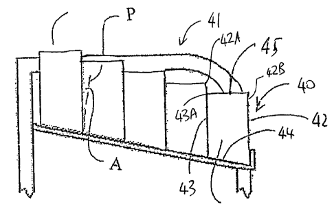
In Figure 3A is a side elevational view of the same conventional shelf
of the rack of Figure 1 with a second embodiment of the modified product
container
boxes according to the present invention placed on it. In this arrangement,
each
container 40 of the row 41 of containers on the inclined shelf has a front
wall 42, a
rear wall 43, a bottom wall 44 and a top wall 45 where the front wall 42
extends from
the base to a top edge 42A which is higher than a top edge 43A of the rear
wall 43
thereof. In this way the bottom wall 44 lies fiat on the shelf at the shelf
angle and the
front and rear walls stand vertically upwardly to the top wall 45 which is
horizontal.
In this way, a portion 426 of the front wall at the top edge 42A of the
front wall is exposed above the top edge 43A of the rear wall of the next
adjacent
container of the row. In the situation where the containers are basically
rectangular
and the edges straight, this causes the exposed portion to form a strip across
the top
edge. As shown in Figure 36, which is a front elevational view of the row of
containers of Figure 3A showing the row of front strip portions exposed at the
front
face of the row, each container of the row has the portion 426 thereof
exposed.
CA 02749906 2013-05-01
13
Thus, when viewed in front elevation, the portions 42B of the containers of
the row
are visible each behind the next.
The portions of the containers of the row contain product data 42X
printed thereon which preferably includes a machine readable code 42Y.
In this arrangement, each container has a top wall which is inclined to
the bottom wall at an angle substantially equal to the shelf angle so as to be
substantially horizontal in position on the rack.