Note: Descriptions are shown in the official language in which they were submitted.
CA 02749991 2011-07-18
WO 2010/086618
PCT/GB2010/000156
1
IMPREGNATED CLOTH
Technical Field
The present invention relates to a cloth that has been impregnated with a
material that, when mixed with a liquid, will set, or, in one embodiment, will
set
when exposed to radiation. Such cloth has numerous applications.
Technical Background
WO 2005/124063 describes a shelter that includes a ground sheet and a
cover; the space between the ground sheet and the cover can be inflated by
pumping air into the space to raise the cover and form the shelter. The cover
is made of a fabric that has been impregnated with cement; the fabric may be
a type of felt known as "wadding", which is a loose non-woven fabric.
Immediately before the interior space is inflated, the cover is wetted with
water, so that, after inflation, the cement in the cover sets and forms a
rigid
shell that acts as a self-supporting roof for the shelter, which is
particularly
useful in providing temporary accommodation in emergency areas.
W02007/144559 discloses a fabric comprising a pair of opposed faces and
self-supporting yarns (also called linking fibres) extending between the faces
that maintain the faces in a spaced-apart arrangement and a solid powder
material located in the space between the faces. The powder material is
capable of setting to a rigid or semi-rigid solid mass on the addition of a
liquid
or on exposure to UV radiation and may comprise cement that will set to solid
cement or concrete on the addition of a water-based liquid. The amount of
settable material in the space in the fabric is such that, particularly when
the
material has set, it occupies substantially the whole of the space between the
first and second faces. The fabric (without the powder material) may be
spacer fabric, which is known and commercially available. The thickness of
the spacer fabric is determined during manufacture by choosing an
appropriate length for the linking fibres.
CA 02749991 2011-07-18
WO 2010/086618
PCT/GB2010/000156
2
US-4495235 discloses a flat body containing a core made of cement and
aggregates placed between a cover layer and a backing layer. The layers and
the cores are needle bonded together prior to the hardening of the cement so
that the layers will hold together in a deformable state.
The term "cloth" or "filled cloth" will be used in the present specification
to
denote a spacer fabric having an internal space containing settable powder
material. A "spacer fabric" is a fabric having a first face and a second face
separated from each other by a space and also has self-supporting linking
fibres extending between the first and second faces that maintain the first
and
second face in a spaced-apart arrangement. The settable powder material will
also be referred to as the "fill"; the fill may include both material that
reacts
with the liquid to cause the fill to set, which will be referred to as the
"reagent",
and materials that do not react with the liquid, e.g. auxiliaries and inert
materials such as fillers.
One problem with powder filled cloth is that the fill spills out of the open
edges
of the spacer fabric, causing a mess during the manufacture, transport and
use of the cloth, and the loss of the fill in the edge region of the fabric
makes
the properties of the edge region different from those of the rest of the
cloth,
and often the edge region must be removed when the cloth is used.
Additionally some powdered fillers, particularly those having a melting
temperature that is substantially different from the fibres of the spacer
fabric,
for example cement and most fillers, make heat cutting and sealing difficult
or
impossible for two reasons: firstly, they remain as powders and clog the
melted plastic preventing it acting as a sealing material and secondly they
increase the heat input required for effective heat cutting and clog the
cutting
blade preventing it from melting the spacer fabric fibres neatly. Therefore in
order for heat sealing to work the cloth must be cut mechanically and the
powder must be first removed from the edge being sealed; a preferred
method is to suck the powder out in the area adjacent to the edge using a
vacuum, then apply heat and pressure to seal the faces. However the multiple
CA 02749991 2011-07-18
WO 2010/086618
PCT/GB2010/000156
3
steps in the process make it time consuming and laborious or require
expensive and bulky machinery, also the process is often unreliable and slow
due to the requirement to have a dust free surface for effective heat sealing.
A further problem with filled cloth is that it is difficult to control the
amount of
liquid that is added during the setting procedure. If the amount of liquid
added
is less than that required to completely set all the reactive material in the
fill,
some of the reactive reagent will be wasted and could have been replaced by
cheaper inert filler. Ultimately, a region may remain in the middle of the
cloth
that contains unset material, resulting in a significant reduction in the
properties of the cloth. Although a problem initially, if the setting liquid
is water
and the cloth comes into contact with water in use, e.g. because it is exposed
to rain, then the reagent may become fully set in use. More generally,
particularly where the amount of liquid added is only slightly less than the
optimum the unset material will be distributed throughout the set material
resulting in only slightly lower than optimum mechanical properties.
On the other hand, if too much liquid is added, the consequences can be
much more severe, for example the fill may be converted into a slurry and
washed out of the cloth. Also, the excess liquid will not react and instead
will
remain within the fill while the reagent sets; the liquid may drain out of the
cloth after setting, leaving voids in the set fill, thereby reducing the
density of
the set material. This can result in a high level of porosity in the final set
product, which can result in a significantly lower final strength and also a
lower resistance to liquid ingress, which is undesirable for applications
where
the cloth acts as a barrier to liquids. Furthermore a high level of porosity
can
result in other undesirable properties, for example: an increase in
susceptibility to freeze/thaw damage and chemical attack.
The adding of the correct amount of liquid is time-consuming and requires the
use of trained personnel.
CA 02749991 2011-07-18
WO 2010/086618
PCT/GB2010/000156
4
The present invention provides improvements in filled cloth and especially
provides a solution to the above problems.
Disclosure of Invention
According to a first aspect of the present invention, there is provided a
flexible
cloth that can be set to become rigid or semi-rigid, the cloth comprising:
a first face;
a second face separated from the first face by a space;
self-supporting linking fibres extending between the first and
second faces that maintain the first and second face in a spaced-apart
arrangement; and
a powder material located in the space between the first and
second faces, which material is capable of setting to a rigid or semi-
rigid solid on the addition of a liquid or on exposure to radiation,
wherein, at one or more edges of the cloth, the first and second faces are
connected by an elastic yarn that at least partly closes the space at the
edge.
The elastic yarn (which will be referred to as the "edge yarn") will normally
be
shorter than the self-supporting linking fibres, thereby at least partly
closing off
the space at the edge of the fibre but, when stretched, can have the same (or
greater) length as the rest of the connecting fibres in the spacer fabric but
when allowed to contract under its own tension, it achieves the desired
shorter length. The elastic yarn may stretch by more than 100% of its length
without breaking. This allows the same machine to be used to form the edges
of the spacer fabric as is used for forming the rest of the spacer fabric; at
the
edge(s) of the spacer fabric, the elastic yarn can be used in place of some or
all (and preferably all) of the normal linking fibre yarns with the elastic
edge
yarns being woven or knitted in a stretched condition. After the fabric has
been removed from the machine used to make it, e.g. a knitting machine, the
elasticity in the edge yarns causes the faces of the fabric to be drawn
towards
CA 02749991 2015-03-23
each other at the edge of the cloth, thereby at least partly closing the space
within the fabric
at its edges.
The part or full closure of the edges of the space in the cloth means that,
when the powder
material is filled into the space, it is constrained to remain within the
cloth and can less easily
spill out of the sides.
This aspect of the present invention can be implemented by providing an
extension at the
edge of one or both faces that extends laterally beyond the rest of the face
and that is
connected to the rest of the fabric by the elastic yarns; the elastic yarn at
the edge of the
cloth then draws the extended portion towards the other face, thereby at least
partly closing
the space at the edge.
The extended edge may also be longer than the distance between the two faces
such that
when the extended portion is drawn up the edge extends vertically above the
face for a short
distance.
The powder material may be settable on the addition of water and in one
embodiment may
comprise cement, optionally Portland cement or high alumina cement (the latter
having the
advantage that it provides shorter setting times and a more rapid gain in
early strength than
other cements) or a combination of these cement with each other or with other
cements. The
fill may include fillers, e.g. sand or fine aggregates, fly ash, glass beads,
low density or
recycled fillers, chopped natural or synthetic fibres, lime flour, mica
insulators, surface
modified silica, pigments, anti-fungal-agents and anti-radiation fillers. The
cement may be
combined with additives customarily found in cement or concrete compositions.
Thus a
number of reaction modifiers may be included for example lithium compounds,
sodium
compounds, organic compounds (citric acid, tartaric acid), sulphate sources,
plasticisers,
accelerants, retarders, super plasticisers, shrinkage reducing
CA 02749991 2011-07-18
WO 2010/086618
PCT/GB2010/000156
6
agents, water repellent agents and dispersible polymer powders). The liquid
used to set the cement is water which may be sea water or water that has
been modified by the addition of other chemicals which may include any of the
above additives that are water soluble.
Alternatively, the settable material may be one component of a multi-part
curable resin that cures when two or more liquid components are mixed
together, e.g. an epoxy resin system. In accordance with the first aspect of
the
present invention, the powder may be a UV settable material.
The second aspect of the present invention relates to a way of controlling the
amount of liquid added to the cloth.
At least one of the first and second faces is porous to the setting liquid,
and
the other face may be porous or non porous to the setting liquid or indeed
impermeable to any liquid or gas. The linking fibres limit the gap between the
two faces and hence limit the maximum internal volume. The liquid is added
to the cloth and passes through one (or possibly both, if provided) porous
faces before soaking into the fill and reacting with the reagent to cause the
cloth to set into a rigid sheet.
The density of the powdered fill material trapped between the first and second
faces in the cloth is related not only to the material density of the grains
of the
reagent and ancillary materials in the fill, but also to the packing of the
fill,
particularly the amount of space that is occupied by air due to the imperfect
tessellation of the particles (void fraction). It is possible by careful
adjustment
of the manufacturing conditions and also selection of the reagents and other
ancillary materials, especially the nature of the filler material, the
specific
particle size distributions, densities and ranges of shapes of the particles,
to
control the packing density of the particles and hence the void fraction
within
the fill that is loaded into the material. Once the fill has been loaded and
CA 02749991 2011-07-18
WO 2010/086618
PCT/GB2010/000156
7
sealed into the material it cannot leave, hence the void fraction can be fixed
at
the point of manufacture.
On addition of the liquid, air is displaced from the void fraction, some of
the
reagent is dissolved in the liquid and additionally the liquid causes the
reagent
to swell. If unrestrained, this expansion will continue until the reagent is
entirely suspended or dissolved in the liquid. In accordance with the second
aspect of the present invention, the volume of the space between the two
faces of the cloth is limited by the linking fibres constraining how far the
faces
can be moved apart (in the context of the setting of the fill and the forces
applied to them in such a process, the linking fibres are of a fixed length).
The
faces may be of a sufficiently closed construction that neither will permit
the
passage of the reagent or filler even when saturated in the liquid. Hence the
fabric can constrain the swelling of the reagent and so the increase in the
volume of the fill can be controlled.
Therefore, in this arrangement, it is possible to limit the quantity of the
liquid
that can be added to the fill for a given area of cloth. This is primarily
achieved
by adjusting the void fraction within the fill and setting the properties of
the
linking fibres, e.g. their length, stiffness and the quantity of the linking
fibres
within the fabric so that the space available to accommodate the liquid,
including an allowance for a small amount of expansion that results due to the
pressure exerted by the swelling of the fill during addition of the liquid
(the
allowance for a given fill is governed by the stiffness and quantity of the
linking fibres), equals the amount of liquid that is required to be added.
By control of the following variables in manufacturing, it is possible to
produce
a filled cloth where the void ratio and swelling is controlled so as to limit
the
space available to be occupied by the liquid component:
= the arrangement, shape and physical properties of the linking fibres,
= the selection of the filler materials with suitable physical
characteristics
including density and particle size and shape distributions,
CA 02749991 2011-07-18
WO 2010/086618
PCT/GB2010/000156
8
= the selection of the reagents with suitable physical characteristics
including density and particle size and shape distributions,
= careful control of the manufacturing process especially loading the fill
to the correct bulk density within the material and
= control of the ratio of reagents and fillers within the dry fill.
If for example the space available is controlled to be close to the optimum
amount of liquid required to be added to set all the reagent, then no matter
how much liquid is present around the cloth it is impossible to add too much
liquid to the interior of the cloth. This has significant advantages
including:
1. The material can be immersed and (as in the preferred embodiment
where the liquid is water) will set underwater without significantly
altering the properties of the set material.
2. The risk of errors from user mistakes is reduced significantly.
3. The level of training and skill necessary to correctly use the cloth is
reduced.
4. If additional liquid contacts the cloth, for example if it is set in the
rain, it
will not alter the properties of the set material.
According to this second aspect of the present invention, there is provided a
flexible cloth that can be set to become rigid or semi-rigid, the cloth
comprising:
a first face;
a second face separated from the first face by a space;
self-supporting linking fibres extending between the first and
second faces that maintain the first and second face in a spaced-apart
arrangement; and
a compacted powder material located in the space between the
first and second faces, which material is capable of setting to a rigid or
semi-rigid solid on the addition of a liquid,
wherein both the first and the second faces are substantially impervious to
the
powder material but at least one of them is pervious to liquid and wherein the
CA 02749991 2011-07-18
WO 2010/086618
PCT/GB2010/000156
9
amount and type of reagent in the compacted powder material, and the
volume and compaction of the powder material are such that:
MV ¨ OV = x LV
where:
MV = the maximum volume of the space within the cloth (per unit area
of the cloth); thus MV includes both the volume of empty space
in the cloth before addition of the powder material, and an
additional volume resulting from any expansion of the space due
to the pressure exerted by the swelling of the powder material
during the addition of the liquid or during the setting of material.
The additional volume may be modified by adjusting the quantity
and stiffness of the linking fibres but will generally be of the
order of up to 15%, e.g. about 12%, of the volume of empty
space in the cloth before addition of the powder material;
OV = the volume of the space within the cloth that is occupied by the
particles of the powder material, which volume does not include
the volume occupied by voids within the powder material (per
unit area of the cloth);
LV = the volume of liquid (per unit area of the cloth) that results in the
maximum long term (28 day) compressive strength, of the fill
blend when set; this can be derived empirically or from the
reagent manufacturer/blenders recommended liquid to
reagent/blend ratio; and
x= a factor between 0.65 and 1.1
The factor x may be less than 1, e.g. 0.85 ¨ 0.99, such as 0.87 - 0.91. For
example using a particular HAC based Cement formulation, where the liquid
is water, the value of x used is 0.89.
In other words, the cloth is such that (and especially compaction of the
settable material and the amount of reactant in the settable material and the
maximum volume between the faces are such that) only a predetermined
CA 02749991 2011-07-18
WO 2010/086618
PCT/GB2010/000156
amount of liquid can be accommodated within the space and that amount is
matched to the liquid required to set the reagent. Thus it is not possible in
normal use to add too much liquid to the interior of the cloth.
5 Generally, due to inevitable variations in manufacturing conditions and
materials, there may be slight variations in the optimum amount of liquid to
be
added, i.e. the minimum amount of liquid required to set the reagent fully; it
is
generally preferable to err on the side of adding too little liquid than too
much,
i.e. the factor x is preferably less than 1. In some cases however it is
desirable
10 to deliberately use above or below the theoretical optimum amount of
liquid.
For example for certain applications it may be desirable to have a high level
of
porosity and hence a ratio of liquid to reagent that is higher than the
optimum.
In other instances a low ratio may be desirable for example unreacted reagent
can impart limited self-healing properties to a material as cracks can allow
liquid to penetrate the set material and react with the unreacted reagent held
within the set material.
In order to achieve the desired ratio it is typically necessary to obtain a
relatively high density of dry fill within the cloth, i.e. the fill is
compacted within
the fabric. In addition to controlling the liquid to reagent ratio, a high
density of
dry fill also has the following advantages:
1. The dry fill is less prone to movement within the material when
subjected to external forces for example: vibration during transport.
2. The wetted fill is less prone to movement due to liquid movement when
the liquid is added, for example if the liquid is added by spraying or
jetting onto one of/or the porous face(s).
3. When the material is manipulated, or folded, the dry, or wetted but
unset fill is less likely to move, which may result in weakened area or
line in the set material.
4. In some cases a denser level of reagent will evolve more heat per unit
area which can advantageously accelerate the reaction and also
enable the reaction to occur at low temperatures.
CA 02749991 2011-07-18
WO 2010/086618
PCT/GB2010/000156
11
It should be noted that the dry fill must not be so compacted as to either
reduce the void fraction to a value below that where there is insufficient
space
within the cloth to allow the desired amount of liquid to be accommodated or
that the fill particles are so closely packed that they restrict the passage
of
liquid through the fill to such an extent that an insufficient quantity of the
liquid
is able to contact the reagent element within the fill and hence an
insufficient
fraction of the reagent is able to react. In practice this undesirably high
level of
compaction is difficult to achieve in most cases.
Although WO 2007/144559 teaches that the amount of settable material in the
space in the fabric is such that, particularly when the material has set, it
occupies substantially the whole of the space between the first and second
faces, it does not teach that the mix and density (i.e. degree of compaction)
of
the settable material should be selected that it complies with the above
formula and so can be used to control the water to cement ratio and so
optimise the physical properties of the cloth when set by avoiding the
possibility of adding too much liquid. This allows the cloth to be set in the
presence of excess liquid, e.g. under water, while still providing the desired
physical properties. In the case of a cement filled cloth, which is the form
of
cloth that is specifically exemplified in WO 2007/144559, the present
invention
generally requires a careful selection of the filling materials and a greater
degree of compaction than was apparent from WO 2007/144559 in order to
comply with the above formula.
The settable powder material and/or the liquid can include additives e.g.
flexiblizers, foaming agents, fillers, reinforcement materials etc. that are
known in the art in connection with the settable materials concerned, as
described above.
The settable material is preferably added to the space through pores formed
in the first face of the fabric, in which case, the first face will have pores
that
CA 02749991 2011-07-18
WO 2010/086618
PCT/GB2010/000156
'
12
are large enough to allow the material to be placed in the fabric. However,
after the material has been placed in the fabric, it is desirable to make the
first
face substantially impervious to the fill material and W02007/144559
describes several techniques that can be applied to achieve this.
Firstly, a further layer may be bonded onto the first face after the settable
material has been introduced into the fabric. One such layer could by way of
example be a damp-proof layer, which could find application in the
construction industry or tunnelling.
Secondly, the first face may be made of, or include, an elastomeric yarn so
that the upper face can be stretched to enlarge pores within the face to allow
the settable material to be introduced into the fabric but, once the material
has
been added to the fabric, the stretching forces can be released, to close the
pores to a size such that the settable material cannot readily escape through
the first face.
Thirdly, the first face can be treated after the settable material has been
introduced into the fabric to close the pores of the first face. For example,
it is
possible to treat the first face by applying a sealing material such as an
adhesive or to subject the first face to solvent treatment to fully or
partially
close the pores. In one example, a PVC paste may be applied (for example
using a scraper) to the first face and cured for example by heat, e.g. by
means of radiative heaters or hot air blowers.
Fourthly, the first face can be knitted from fibres that will shrink when
heated,
thereby enabling the settable materials to be introduced through a knit having
pores sufficiently open to allow the particles to pass through; after the
settable
material has been introduced into the fabric, the first face are heated, e.g.
using heated air, causing the fibres to contract to close the pores so as to
substantially prevent the particles of settable materials from escaping.
CA 02749991 2011-07-18
WO 2010/086618
PCT/GB2010/000156
13
A combination of the above procedures may also be used.
The second face is preferably substantially impervious to the settable
material
so that the fill does not fall through the second face when added through the
first face. However, in order to assist in the penetration of liquid into the
space, the second face is preferably porous to the liquid applied to set the
fill.
Thus, the second face preferably includes pores having a size allowing the
liquid to penetrate but not allowing material particles to pass through. If
nevertheless the second face has pores that are too large to retain the
material within the space, it is possible to prevent the material falling out
through the second face using any of the measures discussed above.
As already mentioned, the second and in some cases the first face of the
fabric may be such that the liquid can penetrate into the space through the
faces to contact the settable powder material within the space. Such liquid
penetration can take place either by including pores within the face (as
discussed above) and/or by making the yarns of the first and second faces
from a material that can be wetted by the liquid concerned and therefore the
liquid will be wicked through the first and second faces to come into contact
with the settable material within the fabric. Furthermore, capillary action
between fibres within the first and second faces can assist in providing
liquid
to the settable material. Suitable materials for use in forming the first and
second faces include:
= polypropylene, which is the preferred material to use when the settable
material includes cement, as it has excellent chemical resistance to
alkaline conditions;
= coated glass fibres, which can provide reinforcement to the set
material;
= polyethylene;
= PVC fibres, which have the advantage of being relatively easy to bond
using chemical or thermal bonding.
A mixture of fibres can be used.
CA 02749991 2011-07-18
WO 2010/086618
PCT/GB2010/000156
14
The linking fibres in the fabric are self-supporting and should be
sufficiently
stiff, i.e. they should be sufficiently resistant to bending under forces
tending
to crush the fabric, to maintain the spacing between the faces when the
settable material has been loaded onto the first face to feed the material
into
the fabric. The density of the linking fibres, i.e. the number of yarns per
unit
area, is also an important factor in resisting crushing forces while the
material
particles are being added and so maintaining the spacing between the faces
and in restricting the movement of the material particles once they are
trapped
between the upper and lower layers. The linking fibres are generally made of
the same material as the faces, as listed above. Generally the linking fibres
are a monofilament as this provides the greatest stiffness.
It is important, in accordance with the present invention, that the linking
fibres
do not divide the space within the fabric into individual small closed
compartments since such a division would allow cracks to propagate within
the fabric and so reduce the strength of the fabric once the material has set.
The particle size of the settable material must be sufficient to allow it to
be
introduced into the fabric but it should not be so fine as to fall out of
pores in
the first and/or second faces. Especially preferred are high alumina cements
since among other attributes they provide shorter setting times and a more
rapid gain in early strength than other cements.
The first and second faces and the linking fibres are preferably part of a
spacer fabric, which can be formed with pores in the first and second faces by
the knitting process used to make it. The second face is preferably more
tightly knitted than the first face so that the pores in the second face are
smaller than in the first face to allow the settable powder material to be
introduced into the space through the relatively large pores in the first face
and prevent the material falling out of the fabric through the second face.
CA 02749991 2011-07-18
WO 2010/086618
PCT/GB2010/000156
The cloth of the present invention can be manufactured and caused to set at
will any time later by the addition of the liquid, e.g. water. The fabric can
therefore be made at one location, transported to another location, where it
is
caused to set by the addition of the liquid, which can be supplied locally,
5 thereby reducing the bulk that must be transported. The fabric
impregnated
with the solid powder will still be flexible and can be folded or rolled up
for
transport.
The fabric of the present application has many applications. Firstly, it can
be
10 used to form the cover of a prefabricated shelter as described in WO
2005/124063. However, it has wider applications and, for example, can be
used:
= to form a track-way for vehicles, pedestrians or animals;
= to form a shelter by applying the fabric to a framework;
15 = to make formwork for casting concrete;
= to form barriers, e.g. to line tunnels;
= to repair or reinforce structures, e.g. roofs;
= to form floors or damp proof structures;
= to reinforce earth structures, e.g. river banks and unstable slopes;
= to provide flood defences;
= to repair existing pipes, including buried water pipes or to construct
new pipes;
= to fireproof elements of new or existing structures e.g. as a fireproof
covering or lining for chimneys;
= to form a hard surface, reduce dust hazards and contain fuel spills for
aircraft e.g. helicopter landing sites and runways;
= to reinforce sandbag structures and protect them from damage from
the elements such as wind and ultra violet degradation;
= to line ground works and prevent the leaching of chemical
contaminants eg. for land fill or secondary fuel containment works;
CA 02749991 2011-07-18
WO 2010/086618
PCT/GB2010/000156
16
= to form a waterproof lining for the containment of water e.g. pond,
canal lining and water storage or settling or septic tanks;
= to form permanent awnings or roof structures;
= to line drainage ditches;
= to provide an external weatherproof facing for buildings;
= to form an integral part of a durable gabion structures;
= to repair and/or reinforce gabion structures and protect them from
damage from the elements such as wind and ultra violet degradation;;
= to form artistic or decorative forms, or
= to form hulls and superstructure of floating vessels such as boats or
pontoons.
If the settable material is set by the addition of water, the water can be
added
deliberately or the fabric can be put in a place where it will come into
contact
with water, e.g. in a watercourse or outside where it can absorb rain. For
example, it is possible to bury the fabric in damp earth and allow it to
absorb
water from the earth, thereby causing the settable material to set.
Once the cloth has set, the fibres also provide reinforcement to the set fill
material and substantially increase its strength and, if the fill material
becomes
cracked, it allows the cloth to fail progressively (rather than
catastrophically)
by taking up load on the cloth..
There is theoretically no limit to the thickness of the cloth, although it
will
generally be limited by the manufacturing techniques used to produce it. A
typical thickness would be between 2 and 70mm, e.g. from 2 to 40mm, and
typically between 4 and 30mm, e.g. from 4 to 20mm. One important
consideration limiting the thickness of the material is the ability of the
liquid to
penetrate through the interior of the settable material before the outer
portions
of the settable material has set. A further limitation on the thickness comes
from the increased weight of the fabric with increased thickness and if it is
too
CA 02749991 2011-07-18
WO 2010/086618
PCT/GB2010/000156
17
thick, the faces may not be able to support the weight of the settable
material
within the fabric.
Brief Description of Drawings
There will now be described, by way of example only, a fabric material in
accordance with the present invention, by reference to the accompanying
drawings in which:
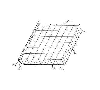
Figure 1 is a diagrammatic illustration of a spacer fabric;
Figure 2 is a cross sectional view through the fabric;
Figure 3 is a diagrammatic illustration of spacer fabric according to one
embodiment of the present invention; and
Figure 4 is a needle diagram for knitting the spacer fabric of Figure 3.
Detailed Description
Referring to the accompanying drawings, Figure 1 shows a schematic knitted
spacer fabric having a tightly knitted bottom face layer 10, a more loosely
knitted upper face layer 12 and linking fibres 14 extending across the space
16 between the lower and upper face layers 10, 12. The spacer fabric is made
of knitted polyethylene and is commercially available from Scott & Fyfe as
5mm spacer fabric.
Settable material, e.g. cement optionally together with fillers and other
additives, is introduced into the fabric through pores 20 in the open-knit
upper
face layer 12. The pores 20 arise through the knitting process during
manufacture of the spacer fabric. The cement can be placed on the spacer
fabric and will fall through pores 20 into space 16. The penetration through
the pores 20 can be assisted by placing the spacer fabric on a vibrating bed
and by brushing the fill into the pores, e.g. using a rotating brush.
Vibration
also has the advantage of settling the cement within the space 16 to minimise
voids or air pockets that are formed.
CA 02749991 2011-07-18
WO 2010/086618
PCT/GB2010/000156
18
The bottom face 10 has a relatively tight knitted structure and the pores in
the
bottom face are smaller than in the upper face layer such that the pores are
sufficiently small to prevent substantial amounts of the cement from falling
out.
After the material has been introduced into the space 16, the upper face layer
12 is sealed by the application of a thin coat of PVC paste which is then
cured
by heating the surface.
Water can penetrate into the fabric through the pores in the bottom face 10;
hydration of the cement is aided by the linking fibres 14, which can wick
water
into the interior of the fabric.
The cloth including the fabric and the settable fill material within the space
16
is flexible and can be formed to shape prior to the introduction of liquid to
set
the material within the space.
The long fibres 18, together with the shorter fibres in the fabric, provide
reinforcement to the material, when set and prevent crack propagation.
Figure 3 shows a spacer fabric that can be used for making the cloth of the
present invention; except as set out below, it is identical to the fabric of
Figures 1 and 2, and the same reference numbers as are used in connection
with Figures 1 and 2 have been used in Figure 3 to shown the same features.
However, in the fabric of Figure 3, the edge of the lower face layer 10 is
extended beyond the edge of the upper face layer 12 by an extension 24
formed in exactly the same way as the rest of the lower face layer 10 except
that linking fibres 26 connecting the extension to the upper face 12 is made
of
an elastic material which is stretched during knitting. When the tension is no
longer applied to the elastic linking fibres 26, e.g. by removing the fabric
from
the knitting machine, the extension 24 is drawn up around the edge of the
fabric by the linking fibres 26 and so closes off the edge of the fabric. When
a
CA 02749991 2011-07-18
WO 2010/086618
PCT/GB2010/000156
19
settable fill is added through the pores 20 in the upper layer 12, it cannot
spill
out of the sides of the fabric.
Figure 4 shows the pattern of needles used for knitting the edge of the spacer
fabric shown in Figure 3 where the normal yarns used to form the bulk of the
spacer fabric, e.g. polypropylene, are shown by the letter "N" while the
elastic
used to form the linking fibres 26 are shown by the letter "E".
Example 1
A high alumina cement is loaded into the fabric shown in Figure 3 using the
vibration and brushing techniques described above to form a filled cloth.
Water is used to set the cement. The theoretical optimum water: cement ratio
in this case is 0.4 by weight. The cloth has a porous face 10 of sufficiently
closed construction to prevent the dry cement powder and also the cement
powder once soaked in water from passing through it in significant quantities,
the other face 12 has an impermeable PVC coated face to close off the pores
20. The two faces are linked by monofilament polyethylene linking fibres. The
high alumina cement is compacted to give a total dry density of 1.35g/cm3 and
an average thickness of 7.3mm between the outer surfaces of the two faces.
The linking fibres are spaced, slightly bowed and of sufficient stiffness such
that after immersion in water the swelling of the cement powder between the
two faces is constrained to a 14% internal volume increase. When this
increased volume is entirely filled with water as a result of immersion this
represents a 10% increase in the weight of the material. In addition to the
increase in volume, the water also displaces air from the void fraction and
dissolves a proportion of the cement which results in a further 22% increase
in
weight.
Continued immersion does not result in any further increase in weight.
Therefore, the cloth construction limits the water to cement ratio to 0.32
being
CA 02749991 2011-07-18
WO 2010/086618
PCT/GB2010/000156
slightly below the 0.4 optimum to provide the maximum 28 day compressive
strength. In other words, the factor x in the above formula is 0.32/0.4 = 0.8.