Note: Descriptions are shown in the official language in which they were submitted.
CA 02750667 2011-07-25
WO 2010/090947 PCT/US2010/022462
1
GOLF PLANE TRAINING DEVICES
This application claims priority to U.S. Provisional Patent App'n Ser. Nos.
61/149,730, filed 4 February 2009, and 61/299,017, filed 28 January 2010, the
complete disclosures of which are incorporated herein by reference.
Field of Inventions
The inventions relate to devices that can be used during a full golf swing and
golf
ball strike to train the golfer to swing the club on the proper golf shaft
plane.
Background of the Inventions
Golf clubs generally have three parts, the grip, the head, and the shaft that
connects the grip to the head. The head, has a face designed to contact a golf
ball. Each face has a sweet spot which is the most efficient portion of the
face at
transferring the force from the moving golf club to the ball.
Golf swings can be broken down into the following three parts. The address is
when the golfer places the golf club behind the resting ball in a ready
position to
hit the ball. The backswing is when the golfer moves the club backward away
from the ball, which mostly involves rotating the club around the golfer's
body.
The downswing is the movement of the club back to the ball, which mostly
involves rotating the club in the opposite direction to the backswing.
The word "plane" was made popular by Ben Hogan many years ago. When
viewed from the side of the golfer during the downswing, the plane is an
invisible
line on which the shaft of the club should travel toward the ball. For a
baseball
swing, that plane is basically parallel the ground. However, since the golf
ball is
resting on the ground, the club moves back into the ball at an angle to the
ground
and, thus, the swing plane is at an angle to the ground. The swing plane is
optimally the same angle as the angle of the shaft during address. If the club
is
CA 02750667 2011-07-25
WO 2010/090947 PCT/US2010/022462
2
properly fitted to the golfer, the angle of the shaft during address will be
the same
as the lie angle of the club.
In most golf shots, the desired club shaft approach to the ball during the
downswing is from the inside and then after contact the shaft moves again back
inside, like a big gentle curve. While this movement sounds simple, the proper
movement is not only very difficult to attain but also to retain.
U.S. Patent No. 482,836 discloses a golf swing training device. This device
uses
rigid rails to align the head of a golf club during the swing. The use of such
rigid
rails provides a danger of causing damage to the golf club and/or golfer
during a
full golf swing. Furthermore, the rails do not provide a clear visual
representation
of the downswing golf shaft plane in either the vertical direction or the
horizontal
direction. The rails cannot be made narrower than the width of the club head,
and in fact, must be far further apart than the width of the club head to
allow the
club head to move freely there between. Thus, this device cannot show the
shaft
plane, which is narrower than the width of the club head. Moreover, this
device is
large and cumbersome.
U.S. Patent No. D407,773 discloses a golf club swing path and face angle
measuring device. Fig. 2 shows a curved path the club head takes. The bristles
extending from the base in a horizontal direction are sized and placed to
direct
the club head. Since the club head can rotate during the swing, directing the
club
head will not ensure that the club shaft is on the correct plane. Furthermore,
the
curved path of the bristles does not provide a clear visual representation of
the
downswing golf shaft plane in either the vertical direction or the horizontal
direction.
U.S. Patent No. 7,431,661 discloses a golf swing and putting trainer. The
trainer
includes rigid guides 31 and 32. While the rigid guides 31 and 32 can
optionally
be padded with foam, the use of such padded rigid rails provides a danger of
causing damage to the golf club and/or golfer during a full golf swing.
Furthermore, the use of rigid foam padded guides does not provide a clear
visual
CA 02750667 2011-07-25
WO 2010/090947 PCT/US2010/022462
3
representation of the downswing golf shaft plane in either the vertical
direction or
the horizontal direction. Moreover, since the guides are rigid, they must be
placed far apart to ensure that the club does not contact them during use and
the
minimum distance between the guides is far larger than the length of a golf
club
head.
There are no known devices that can be used during a full swing to contact a
ball
so that the proper shaft plane can be quickly learned and grooved in.
Furthermore, there are no known devices that are easily portable for use at
any
desired location, such as a golf range.
Summary of the Inventions
The Plane Finder is a training device that will quickly improve golfers' swing
and
ball contact. All great golf shots have a few things in common. The ball must
contact the sweet spot on the club face. The club must approach the ball in a
certain manner, such as not too steep or too shallow, and not too much from
the
inside or the outside. The Plane Finder provides a visual representation of
the
direction the club shaft travels during the down swing so that the club
approaches
the ball on the proper plane, and also from the desired direction. Proper
contact
between the ball and the sweet spot on the club face is also improved by
having
the club shaft on the proper plane.
The Plane Finder is the first training aid designed for golf that will allow a
swing at
full speed and provide feedback on the proper shaft plane. The Plane Finder
provides a track in which the club shaft must basically fit from set up to
thigh high
in the back swing, then upon reaching thigh high on the downswing to impact
and
to thigh high in the follow through. Thus, from thigh high in both directions,
the
club shaft will be running through the Plane Finder. Thigh high is almost
always
identical among tour professionals.
Unlike other commercial training aids such as the Inside Approach, EZ Plane
Trainer, Dual Track Trainer and others, the Plane Finder has top and bottom
side
CA 02750667 2011-07-25
WO 2010/090947 PCT/US2010/022462
4
guides, can be used while hitting balls at full speed, can be adjusted for
poor
golfers and top professionals, gently lets the golfer know when they are off
shaft
plane, and will not damage the club. The guides can be closer than the length
of
the club head to accurately show the shaft plane. For example, for an advanced
golfer the guides can set slight farther apart than the golf shaft, which is
far
narrower than the length of a golf club.
The Plane Finder provides instant feedback when the shaft is off plane. When
the shaft is off plane, one or more guides will deflect or fold back. The
deflected
or folded guide(s) provide feedback as to where in the swing the shaft was
taken
off plane so that the golfer can adjust the swing to keep the shaft on the
proper
plane.
The Plane Finder will also improve the golfer's set up by preventing poor
slouching posture and improper set up, such as being close to the ball or too
tall
that the swing is too straight up and down. The top and bottom guides can be
adjusted for all body types and club lengths. Having a good set-up is often
over
looked in training aids and when addressed it is not combined with being able
to
hit ball at full speed.
The Plane Finder has a bottom guide that will guide the player into impact
without
having the grip of the club approach the ball too low, which often occurs in
better
players, and a top guide that will be used by poor golfers to prevent the
dreaded
over the top swing, which most golfers end up hitting the slice with. Thus,
the
Plane Finder is beneficial for all playing abilities.
After impact, the swing is not over. The club shaft should desirably continue
on
plane and be a replica of the approaching downswing into impact. The Plane
Finder's guides deal with post impact and insures the swing is on shaft plane
until
thigh high is passed.
CA 02750667 2011-07-25
WO 2010/090947 PCT/US2010/022462
The Plane Finder addresses the most commonly mentioned and yet
misunderstood word in golf, shaft plane. The Plane Finder will assist a golfer
in
producing a repeatable approach to the golf ball at a proper angle.
The Plane Finder comprises a base constructed and arranged to provide a first
ground support which during use is on a first side of a resting golf ball
facing a
golfer addressing the golf ball, a second ground support which during use is
on a
second side of the resting golf ball facing away from the golfer addressing
the
golf ball, and a connector connecting the first and second ground supports, at
least two bottom supports connected to the first ground support, at least two
top
supports connected to the second ground support, at least one bottom guide
protruding from each bottom support and at least one top guide protruding from
each top support. The top and bottom guides are deflectable so that when a
golf
shaft contacts the guides during a golf swing the guides deflect without
causing
damage to the golf shaft. The bottom and top guides define a space there
between through which the golf shaft travels during a downswing and follow
through of a golf swing. The space provides a visual representation of a plane
the club shaft travels on the downswing and follow through of a golf swing. At
least one of the guides or supports is movable to provide different plane
angles.
The distance between the bottom and top guides is adjustable to change a width
of the space there between. The guides protruding from the supports are
constructed and arranged to provide clearance for a club head under the guides
and to provide a minimum space width narrower than a width of the club head.
Also provided is a method of obtaining feedback on a golf plane comprising
setting up the Plane Finder, setting a desired plane angle defined by the
space
between the guides, setting a width of the space between the guides that is
wider
than a golf club shaft, placing a golf ball in the Plane Finder, and swinging
a golf
club so that a face of the golf club head strikes the golf ball. The shaft
travels in
the space between the guides, and the head travels below the guides. Feedback
is provided by the space between the guides and when the shaft strikes a
deflectable guide.
CA 02750667 2011-07-25
WO 2010/090947 PCT/US2010/022462
6
Brief Description of the Drawings
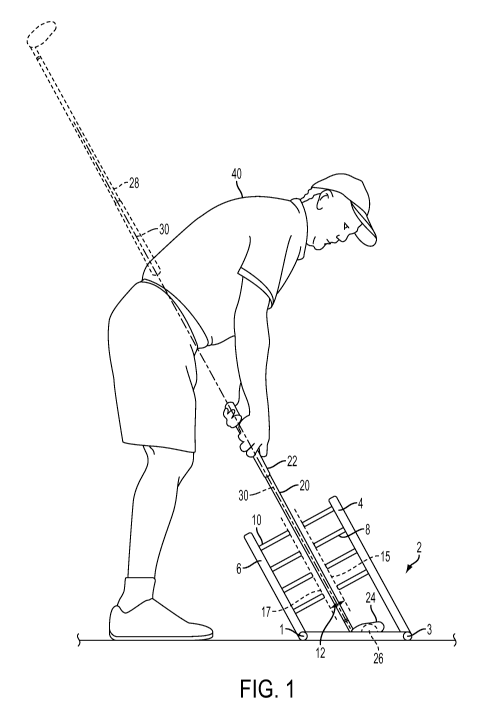
Fig. 1 illustrates a cut away view of the Plane Finder through the resting
golf ball
and golfer;
Fig. 2 illustrates an angled view of the Plane finder;
Fig. 3 illustrates a view of the Plane Finder from the perspective of a golfer
addressing the ball;
Fig. 4 illustrates an example of the guides;
Fig. 5 illustrates an indicator;
Fig. 6 illustrates a view of the parts of an embodiment of the Plane Finder;
Fig. 7 illustrates a side view of a ground support;
Figs. 8A-8C illustrate views of a T-connector;
Figs. 9A-9E illustrate views of a corner connector;
Figs. 1 OA-1 OF illustrate views of an adjustable connector for connecting the
top
and bottom ground supports;
Figs. 11A-11J illustrate views of an angle adjustment structure;
Fig. 12 illustrates a view of an end cap;
Figs. 13A-13F illustrate views of a guide; and
Figs. 14A and 14B illustrate views of a hitting strip.
CA 02750667 2011-07-25
WO 2010/090947 PCT/US2010/022462
7
Detailed Description of the Inventions
The inventions will now be described in reference to the attached non-limiting
drawings.
Fig. 1 shows a cut away view of the Plane Finder 2 though a resting golf ball
26
and a golfer 40. The golf club at impact with the golf ball 26 is shown by the
shaft
20, the grip 22 and head 24. The shaft 28 shows the golf club at approximately
half way through the downswing. The plane 30 is the plane on which the golf
shaft swings through the downswing and follow through.
Though impact, the shaft 20 travels though the Plane Finder 2. The Plane
Finder
2 has at least two top guides 8 spaced apart in a horizontal direction of the
plane
30 and at least two bottom guides 10 spaced apart in a horizontal direction of
the
plane 30. Preferably, the Plane Finder 2 has at least two top guides 8 spaced
apart in a horizontal direction of the plane 30 and at least three bottom
guides 10
spaced apart in a horizontal direction of the plane 30 as shown by the highest
guide 8 on each of the two top supports 4 and by the highest guide 10 on each
of
the three bottom supports 6 in Fig. 2.
As shown in Figs. 1 and 3, the top guides 8 and bottom guides 10 define a
space
having a width 12 that is sufficient to allow the shaft 20 to swing
therethrough.
Preferably, the width 12 is adjustable by the user so that less experienced
golfers
can have a wider width 12 and better golfers can have a narrower width 12 as
desired. Examples of suitable widths 12 are 6 or less inches (15 or less cm),
preferably from slightly greater than a golf shaft thickness to 6 inches (15
cm),
more preferably from 1 to 4 inches (2 to 10 cm).
The guides 8 and 10 should be of a sufficient length to ensure that the shaft
20
and head 24 will not contact the top supports 4 or the bottom supports 6
during a
swing at full speed. Examples of suitable lengths for the guides 8 and 10 are
from 6 to 24 inches (15 to 61 cm), preferably from 10 to 20 inches (25 to 50
cm),
and most preferably from 12 to 15 inches (30 to 38 cm).
CA 02750667 2011-07-25
WO 2010/090947 PCT/US2010/022462
8
As shown in Figs. 1, 2 and 4, the guides 8 and 10 should be arranged on a
sufficient length of the respective supports 4 and 6 to provide a clear visual
representation of the plane 30 in the vertical direction as shown by the
substantially parallel dotted lines at 15 and 17. Examples of suitable
distances
are from 5 to 24 inches (12 to 61 cm), preferably from 6 to 15 inches (15 to
38
cm) and most preferably from 8 to 12 inches (20 to 30 cm). If zip ties are
utilized,
the zip ties can be placed at any desired distance, for example from 1 to 6
inches
(2 to 15 cm) apart, preferably 1 to 2 inches (2 to 5 cm) apart on the length
of the
supports 4 and 6.
The guides 8 and 10 must be higher than the typical height of a golf club head
24
measured from the ground. For example, the bottom guides 10 are usually at
least 6 inches (15 cm), preferably 8 to 18 inches (20 to 45 cm), from the
ground
to provide sufficient clearance for the head 24 to pass thereunder. For
example,
the top guides 8 are usually at least 12 inches (30cm), preferably 18 to 30
inches
(45 to 61 cm), from the ground to provide sufficient clearance for the head 24
to
pass thereunder. The top guides 8 will generally require more clearance than
the
bottom guides 10 because the top guides 8 are angled towards the ground and
the free end of the guides 8 will be closer to the ground than the mounted end
on
the supports 4. In this manner, while the supports 4 and 6 are far apart to
provide sufficient distance for the club head 24 to pass through and avoid
contact
with the supports 4 and 6, the distance between the guides 8 and 10
(represented by width 12) can be far smaller than the length of the golf club
head,
such as slightly greater than the thickness of a golf shaft 20, to provide a
clear
visual image of the plane 30.
The guides 8 and 10 can be formed from any flexible material and shaped as
desired so that the guides 8 and 10 are easily deflectable when struck by a
shaft
20 and return to the static position after being struck by a shaft 20.
Examples of
preferred materials are composites and plastics. Examples of suitable guides 8
and 10 are well known zip ties, as shown in Fig. 4. Zip ties are easily
replaced,
CA 02750667 2011-07-25
WO 2010/090947 PCT/US2010/022462
9
inexpensive, easily obtained, can be easily sized for length by cutting, and
are
easily mounted to the supports 4 and 6 by their known fastening means.
In another embodiment, the flexible guides 8 and 10 can be replaced or include
one or more guides that when deflected by the shaft 20 remain in the deflected
position to provide feedback on which guides 8 and 10 were deflected and by
how much. The golfer can bend the deflected guide back to a starting position
for
reuse. An example of such a guide is a hinged guide.
The Plane Finder 2 can also be used to help setup, address and the start of
the
backswing on the desired plane 30.
While the guides 8 and 10 and supports 4 and 6 can be positioned as desired in
the horizontal direction, preferably, at least one set of supports 4 and 6 are
positioned so that the associated guides 8 and 10 are aligned substantially
opposite one another as shown in Fig. 3.
Thus, the location, size and number of guides 8 and 10 provides a clear visual
representation of the plane 30 in a horizontal direction as shown by the
substantially parallel dotted lines at 14 and 16 and the vertical direction as
shown
by the substantially parallel dotted lines at 15 and 17. This visual
representation
is also made clear because the space between the guides 8 and 10 shown at
width 12 can be made quite small because of the flexible nature of the guides
8
and 10. In general, the smaller the width 12 the more defined the plane 30
will be
to the golfer. Since the guides 8 and 10 can be set slightly greater than the
thickness of the golf shaft 20 and the guides 8 and 10 are above ground level
to
provide clearance for the golf head 24, the plane 30 can be precisely defined
and
suspended in air. Furthermore, the guides 8 and 10 do not materially reroute
an
errant golf swing, in the way rigid guides would. Instead, the flexing of the
guides
8 and 10 provides feedback so that the golfer can adjust the plane of the
shaft 20
in response thereto.
CA 02750667 2011-07-25
WO 2010/090947 PCT/US2010/022462
The Plane Finder 2 includes a ground support on both sides of the ball 26. The
first ground support 1 is on the side of the ball 26 facing the golfer 40. The
second ground support 3 is on the side of the ball 26 facing away from the
golfer
40. The first support 1 and second ground support 3 can be connected by a
connector 11. The ground support should be free of any encumbrance in front
of the ball 26 so that the when the ball 26 is struck at full speed with the
face of
the head 24 the ball 26 is not deflected by the ground support, shown by 13 in
Fig. 2.
The width 12 can, for example, be adjusted by at least one of adjusting the
length
of the guides 8 and/or 10, and/or by adjusting the distance between the first
and
second ground supports 1 and 3. A length adjustable connector 11 can be used
or at least one of the mounts between the connector 11 and the first ground
support 1 or second ground support 3 can be adjustable to adjust the distance
between the first and second ground supports 1 and 3. Another example of how
the width 12 can be adjusted is by adjusting the length of the guides 8 and
10.
The guides 10 are connected to the first ground support 1 by one or more
bottom
supports 6. The guides 8 are connected to the second ground support 3 by one
or more top supports 4. While Figs. 1-3 shows the preferred three bottom
supports 6 and two top supports 4, any desired number of supports 4 and 6 can
be used. However, if the supports 4 and 6 are poles are shown in Figs. 1-3,
there
must be at least two bottom supports 6 and at least two top supports 4 and at
least two guides 8 so the guides 8 can be spaced from one another in a
horizontal direction and at least two guides 10 so that the guides 10 can be
spaced from one another in a horizontal direction to provide a visual
representation of the plane 30 in a horizontal direction, as shown by the
substantially parallel lines 14 and 16 in Fig. 3.
The supports 4 and 6 and ground supports 1 and 3 can be formed from any rigid
material. An example is well known PVC piping and joints to provide
lightweight,
easily erected, weather-resistant device. Another example is aluminum or other
CA 02750667 2011-07-25
WO 2010/090947 PCT/US2010/022462
11
metal. Preferably, the Plane Finder 2 is constructed and arranged to be
foldable
for easy storage and transportation.
The supports 4 and 6 can be movably mounted to the ground support so that the
angle of the plane 30 can be adjusted. Examples of suitable movable mounts for
mounting the supports 8 and 10 to the ground support are shown in U.S. Patent
No. 7,431,661 (at connectors 27 and 31), the complete disclosure of which is
incorporated herein by reference. Another example of a movable support is
shown at 52 in Fig. 5.
The supports 4 are preferably non-movable in relation to one another so that
they
move as a unit to ensure that they remain in a substantially straight line as
the
angle of the plane 30 is adjusted. The supports 6 are preferably non-movable
in
relation to one another so that they move as a unit to ensure that they remain
in a
substantially straight line as the angle of the plane 30 is adjusted. If PVC
or
other piping is utilized, when the mounts should be non-movable the T-
connectors can be glued or otherwise fastened, and when movement is desired
the connectors can be only friction fit without glue. The Figs. 2-4 show PVC
pipe
structures connected using well-known T-connectors and corner connectors. The
T-connectors 21 mounting the supports 4 to the lower support 3 are glued so
that
the supports 4 turn as a unit, and the T-connectors 21 mounting the supports 6
to
the supports 1 can be glued so that the supports 6 turn as a unit. The corner
connectors 23 to the supports 1 and 3 are friction fit so that the supports 1
and 3
can rotate. In this manner the plane 30 can easily be adjusted by turning the
supports 1 and 3.
If desired, the Plane Finder can include an indicator 50 for setting the angle
of the
supports 4 and 6, such as a number or degree indicator.
The height and location of the supports 4 and 6 and guides 8 and 10 should be
sufficient to provide feedback from thigh height of the golfer during the
downswing into contact of the ball 26 and the follow through to thigh height
of the
golfer. Thigh height will be understood to be an average thigh height, such as
CA 02750667 2011-07-25
WO 2010/090947 PCT/US2010/022462
12
from 2 to 3 feet. The height of the bottom support 6 should low enough such
that
a golfer does not contact the bottom support 6 with the hands during the
swing.
Preferably, the height of the top support 4 is longer than the height of the
bottom
support 6, as shown in Fig. 1-3, but they can any desired height relative to
one
another. Examples of suitable heights for the bottom support 6 are from 6 to
24
inches (15 to 61cm), preferably 10 to 18 inches (25 to 45 cm). Examples of
suitable heights for the top supports 4 are from 10 to 30 inches (25 to 76
cm),
preferably 12 to 24 inches (30 to 61 cm). If desired, the supports 4 and 6 can
be
height adjustable.
Preferably, the bottom guides 10 extend further in the horizontal direction as
shown in Figs. 1-3 to provide feedback during the follow through after contact
with the ball 26. Any desired length of the Plane Finder 2 can be used. To
provide feedback in both the downswing and follow through at thigh height, the
distance between the farthest apart bottom guides 10 in the horizontal
direction is
preferably from 4 feet to 8 feet, and the distance between the farthest two
top
guides 8 in the horizontal direction is preferably 4 feet to 6 feet.
Another embodiment of the Plane Finder 2 is illustrated in Figs. 6 through
13F.
Like numbers for this embodiment are as described in the previous embodiments.
The Plane Finder 2 in this embodiment has the same basic setup, dimensions,
and use as described in the previous embodiments set forth above, but uses
alternative parts for ease of disassembly and assembly as set forth below.
Fig. 6 illustrates an exploded view of the Plane Finder 2. The Plane Finder 2
has
at least two top supports 4, at least two bottom supports 6, first and second
ground supports 1 and 3, and a connector represented by connector sections 11
a
and 11 b formed from polyvinylchloride (PVC). PVC T-connectors 21 are used to
connect the top supports 4 to the second ground supports 3 and the bottom
supports 6 to the ground supports 1. Preferably, the top supports 4 are not
permanently glued to associated T-connectors 21 and the bottom supports 6 are
not permanently glued to associated T-connectors 21 so that they can be
removed and assembled for use as desired. Preferably, the ground supports 1
CA 02750667 2011-07-25
WO 2010/090947 PCT/US2010/022462
13
and 3 are not permanently glued to the T-connectors 21 so that they can be
removed and assembled for use as desired.
The ground supports 1 and 3 have alignment structure 31 disposed at least at
each end thereof and the T-connectors 21 associated with the ground supports 1
and 3 have alignment structure 33, so that when the T-connectors 21 are
mounted on the ground supports 1 and 3, the alignment structures 31 and 33
align the T-connectors 21 so that all of the top supports 4 are parallel with
one
another when mounted in the T-connectors 21 and all of the bottom supports 6
are parallel with one another when mounted in the T-connectors 21. A non-
limiting example of alignment structure 31 is a ridge as shown in Fig. 7. A
non-
limiting example of alignment structure 33 is a recess as shown in Figs. 8A-
8C.
The recess is constructed and arranged to accept the ridge. The alignment
structures 31 and 33 can be sized and shaped as desired, with the only
limitation
being that the alignment structures 31 and 33 align the structure having
alignment structure 31 with the structure having alignment structure 33.
Preferably, the top supports 4 and bottom supports 6 each have associated
alignment structure 31, such as a ridge, and the associated T-connectors 21
have alignment structure 33, such as a recess.
Each ground support 1 and 3 has an associated angle adjustment structure, as
shown in Figs. 11A-11J. The angle adjustment structure includes a rotator 35.
The rotator 35 has a degree scale 36 that shows the angle of the top and
bottom
supports 4 and 6 in relation to the ground and the angle of the plane 30. The
rotator 35 includes an alignment structure 33 to align the angle structure 35
with
the top or bottom supports 4 and 6. The rotator 35 is rotatably mounted to the
corner mount 23. The rotator 35 also includes a slot 37 to adjust the angle of
the
top and bottom supports 4 and 6. While a slot 37 is shown, other structures
can
be used as desired, such as holes or friction mounts. The angle structure
further
includes a flip arm 38 and a connecting rod 39. A first end of the flip arm 38
connects to the ground support 1 or 3 near the rotator 35, such as between the
rotator 35 and the corner mount 23. A second end of the flip arm 38 rotatably
CA 02750667 2011-07-25
WO 2010/090947 PCT/US2010/022462
14
connects to a first end of a connecting rod 39 using a bolt 41 and nut 42. A
second end of the connecting rod 39 rotatably connects to the rotator 35 using
a
bolt 43 located in the slot 37, a nut 44 and knob 45. The bolt 43 can be slid
up or
down in the slot 37 to adjust the angle of the rotator 35. The angle of the
rotator
35 can be fixed by tightening the nut 44 on the bolt 43 using the knob 45. The
connecting rod 39 includes an indicator 70 that indicates the angle on the
degree
scale 36.
A first side of the rotator 35 rotatably mounts in the corner connector 23. As
shown in Figs. 9A-9E, 11A and 111, a screw 80 in the corner connector 23 fits
within the channel 72, which allows the rotator 35 to rotate within the corner
connector 23 but prevents the rotator 35 from being withdrawn from the corner
connector 23 while the screw 80 is present in the channel 72. A second side of
the rotator 35 accepts the ground support 1 or 3. The second side includes an
alignment structure 33 which mates with the alignment structure 31 on the
ground
support 1 or 3, so that the ground support 1 or 3 rotates as the rotator 35 is
rotated.
As shown in Fig. 6, bunge cord 60 is used to bias the sections of the ground
supports 1 to the T-connectors 21 and associated rotator 35. Bunge cord 61 is
used to bias the sections of the grounds supports 3 to the associated T-
connectors 21 and rotator 35. Any desired spring or bunge cord can used as
desired. The bunge cords 60 and 61 can be mounted using end caps 63. As
shown in Fig. 12, the end caps 63 have a hook 64 to which loops at the ends of
the bunge cords 60 and 61 can be removably fastened.
As shown in Figs. 10A-10F, the width 12 can be adjusted by adjusting a length
of
adjustable connector, shown by connector sections 11 a and 11 b. The connector
section 11a is sized to fit within the connector section 11b. The connector
section 11 b has holes 15. A tab 117 is disposed within the connector section
11 a
and protrudes from the hole 119 in the connector section 11 a. The tab 117 is
biased so that it protrudes from the hole 119 unless pushed into the hole 119
by
a user. When the connector section 11a is disposed within the connector
section
CA 02750667 2011-07-25
WO 2010/090947 PCT/US2010/022462
11 b, the total length of the connector can be adjusted by pushing the tab 117
in,
moving the connector section 11 a in relation to the connector section 11 b,
and
then setting the total length be allowing the tab 117 to protrude through the
hole
119 and one of the holes 115.
The connector section 11 a has an alignment structure 31, such as a ridge, and
the connector section 11 b has alignment structure 33, such as a recess. In
this
manner, the alignment structure 31 on the connector section 11a and the
alignment structure 33 on the connector section 11 b ensure that when the
connector section 11 a is inserted into the connector section 11 b, that the
connector sections 11 a and 11 b are properly aligned for use.
The connector sections 11 a and 11 b are connected to the ground supports 1
and
3 using associated corner mounts 23, shown in Figs. 9A-9E. The corner mount
23 has a opening for accepting the section 11 a. A short piece of section 11 a
is
used to connect a corner mount 23 to the section 11 b.
As shown in Figs. 13A-13F, the guides 8 and 10 are formed from a flexible
material and constructed so that the guides 8 and 10 are easily deflectable
when
struck by a shaft 20. The guides 8 and 10 in this embodiment do not return to
a
static position after being struck by the shaft 20. When deflected by the
shaft 20,
the guides 8 and 10 remain in the deflected position to provide feedback on
which guides 8 and 10 were deflected and by how much. The golfer can bend
the deflected guide back to a starting position for reuse. Examples of
preferred
materials are composites and plastics, such as PVC or nylon.
The guides 8 and 10 have a mount 53 that is constructed to slide onto the top
support 4 and bottom support 6. The mount 53 has a protrusion 57 that fits
within
a notch 56 on the alignment structure 31 in the shape of a ridge. The ridge
can
have multiple notches 56 so that the guide 8 can be placed at different
heights
depending upon which notch 56 the protrusion 57 resides. The guide 8 includes
a slot 54 in which the alignment structure 31 can slide as the guide 8 rotates
around the top support 4. The protrusion 57 is at least a length around the
inner
CA 02750667 2011-07-25
WO 2010/090947 PCT/US2010/022462
16
surface of the mount 53 so that the protrusion 57 remains in the notch 56 as
the
guide 8 rotates around the top support 4. The guide 10 and lower support 6
have
the same structure as the guide 8 and top support 4.
The parts of Plane Finder are preferably formed from plastic, but if desired,
the
parts can be formed from other materials such as composites, metals, alloys,
or
any other desired material. While round tube structures for the ground
supports,
connectors, top supports, and bottom supports have been shown, other
structures, such as square tubes, or even solid structures, can be used as
desired. The size of the tubes can be as desired, such as from 1 to 4 inches
(2 to
cm) in diameter.
Also provided is a hitting strip for when hitting on grass, as shown in Figs.
14A
and 14B. After the first hit, a divot will occur which will require moving the
entire
setup after each golf shot. Thus, an optional hitting strip 82 is provided,
having
hole 83 to hold the golf ball in place, and holes 84 for placing tees to hold
the
hitting strip 82 in place.
The Plane Finder can be easily transported, set up on site, and adjusted to
any
desired plane. The golfer simply executes the full swing and if the shaft 20
is off
the desired plane 30, the flexible guides 8 and 10 will provide instant
feedback so
that the golfer can accordingly adjust the downswing path.
While the claimed invention has been described in detail and with reference to
specific embodiments thereof, it will be apparent to one of ordinary skill in
the art
that various changes and modifications can be made to the claimed invention
without departing from the spirit and scope thereof.