Note: Descriptions are shown in the official language in which they were submitted.
CA 02750768 2011-07-26
WO 2010/096918 PCT/CA2010/000254
SECURITY SYSTEM WITH KEYFOB ALERT NOTIFICATION
Background of the Invention
Cross-Reference To Related Application
[0001] This application claims the priority benefits of
U.S. provisional Application No. 61/155,198 filed February 25,
2009 the entire disclosure of which is incorporated herein by
reference.
Field of the Invention
[0002] Embodiments of the present disclosure relate to
security alarm systems and associated methods for protecting
residences, businesses and other premises. More particularly,
the present disclosure relates to a keyfob used with a
security system for qualified events, system status alerts and
other system control functions.
Discussion of Related Art
[0003] Security or alarm systems are installed in premises
to detect hazardous or potentially hazardous conditions. A
security system generally includes a plurality of
detectors/sensors, one or more keypads and a control panel
which contains the system electronics and may include a
communication interface (communicator) for remote monitoring
and two-way communication over telephone or wireless
communication paths. Each of the detectors communicates with
1
CA 02750768 2011-07-26
WO 2010/096918 PCT/CA2010/000254
the control panel to provide notification of an alarm
condition. Examples of possible alarm conditions include
unauthorized entry or the unexpected presence of a person who
may be an intruder, fire, smoke, toxic gas, high/low
temperature conditions (e.g., freezing), flooding, power
failure, etc. In other words, an alarm condition may
represent any detectable condition that might lead to personal
hazard or property damage. Audible and/or visible alarm
devices such as sirens, lights, etc., may also be utilized to
notify occupants of the existence of an alarm condition. The
control panel may be located in a utility room, basement,
etc., and may communicate with the detectors and notification
devices by wired or wireless signal paths. A keypad, which
may also communicate with the control panel via a wired or
wireless connection, is used to arm/disarm the system as well
as providing a means to display various system messages via a
status display screen.
[0004] A typical security system includes an "exit delay"
and an "entry arming delay." An entry delay is preprogrammed
into the security system to allow a homeowner with sufficient
time to disarm the alarm system. These delay times may be,
for example, 60 seconds, but have been getting longer in view
of fines assessed by certain municipalities for false alarms.
During this entry delay time, an audible alert or warning
sound notifies the user that they must disarm the system.
2
CA 02750768 2011-07-26
WO 2010/096918 PCT/CA2010/000254
However, for users that are deaf or hearing impaired, this
audible warning may not be heard or may be drowned out by
other nearby loud noises.
[0005] An exit arming delay allows the end user sufficient
time to exit the protected premises after arming the security
system without triggering an alarm condition. Such a delay
begins when the user arms the system using the keypad before
exiting the premises. However, a user may arm the system and
exit the premises, but may inadvertently leave a door, window
or other detected condition open. If the user is hearing
impaired, they will not be alerted to this condition by the
audible warning. The system will go into alarm causing a
false alarm to be sent to the monitoring service.
[0006] Attempts have been made to solve these problems by
using visual annunciators such as lights to alert the user of
the need to disarm the system before an alarm event
notification is sent to a monitoring facility and/or to the
local authorities. However, a user may not notice these
visual annunciators if, for example, they are improperly
mounted or poorly placed in the premises with respect to the
user. In addition, these visual annunciators may not alert a
hearing impaired or deaf person that they have not armed the
system when leaving the premises.
3
CA 02750768 2011-07-26
WO 2010/096918 PCT/CA2010/000254
[0007] U.S. Publication No. 2008/0303657 entitled "Life
Safety Device for the Hearing Impaired" discloses the use of a
life safety pendant that is used to send a panic message to a
central monitoring facility. A central home panel processes
an alarm event and controls vibration of the pendant to
communicate the event to a hearing challenged user. However,
the pendant and associated system do not provide the user with
status information before an alarm event occurs nor does it
notify the user of system status information. This is
critical since without such notification, unnecessary false
alarms may be transmitted to the monitoring facility. For
example, if a hearing impaired user enters the premises where
an alarm system is activated, the user must disarm the alarm
within the entry delay period. Prior art systems do not
provide notification to the user by vibrating the pendant to
indicate that the alarm is activated and must be disarmed.
Rather, a hearing impaired user is only notified once the
alarm event is sent to the monitoring station which is too
late to prevent unnecessary false alarms. Thus, it is an
object of the present disclosure to provide a keyfob or other
personal device that communicates alarm status information to
a hearing challenged user before false alarms are triggered.
Summary of the Invention
[0008] Exemplary embodiments of the present disclosure are
directed to a device and method for providing vibrational
4
CA 02750768 2011-07-26
WO 2010/096918 PCT/CA2010/000254
alerts to a user of a security system. In an exemplary
embodiment, such a method for monitoring a premises includes
detecting one of a plurality of qualified events at the
premises. A signal is sent from the control panel to a
personal device in response to detection of one of the
plurality of qualified events. The personal device vibrates
in response to the received signal to notify a user of the
qualified event.
[0009] In another exemplary embodiment, a security system
for protecting a premises includes at least one detection
device for monitoring a portion of the premises and a control
panel that communicates with the at least one detection
device. A personal device communicates with the control panel
and is configured to mechanically vibrate upon receipt of a
signal from the control panel representing a qualified event
associated with the security system.
Brief Description of the Drawings
[0010] FIG. 1 illustrates a block diagram of an exemplary
security system in accordance with an embodiment of the
present disclosure.
[0011] FIG. 2 is a flow chart of an exemplary status
notification process utilizing the security system of Fig. 1
in accordance with an embodiment of the present disclosure.
5
CA 02750768 2011-07-26
WO 2010/096918 PCT/CA2010/000254
Description of Embodiments
[0012] The present disclosure will now be described more
fully hereinafter with reference to the accompanying drawings,
in which preferred embodiments of the invention are shown.
This invention, however, may be embodied in many different
forms and should not be construed as limited to the
embodiments set forth herein. Rather, these embodiments are
provided so that this disclosure will be thorough and
complete, and will fully convey the scope of the invention to
those skilled in the art. In the drawings, like numbers refer
to like elements throughout.
[0013] Fig. 1 is a block diagram of a typical security
system 10 embodying the present disclosure installed in a
building or premises. Security system 10 includes a control
panel 20 which generally controls operation of the system. A
number of detection devices 181...18N are utilized to monitor an
area. Detection devices may include, for example, motion
detectors, door contacts, glass break detectors, smoke
detectors, water leakage detectors, gas detectors, etc.
Detection devices 181...18N communicate with panel 20 by a
dedicated wired interconnect 18A, wirelessly 18B, through the
electric (i.e. power) wiring of the premises 18C, or
otherwise. One or more user interfaces, such as keypad 25 is
used to communicate with control panel 20 to arm, disarm,
notify and generally control system 10. The alarm system 10
6
CA 02750768 2011-07-26
WO 2010/096918 PCT/CA2010/000254
further includes a portable personal device 19 such as, for
example, a keyfob or pendant, used to provide vibrational
notification to a user as explained in more detail below.
[0014] Control panel 20 communicates with each of the
detection devices 181...18N, keypad 25 and personal device 19 as
well as communicating with an offsite monitoring service 30
which is typically geographically remote from the monitored
premises in which system 10 is installed. Control panel 20
may include a CPU 34, memory 35 and communicator 36. CPU 34
functions as a controller to control the various communication
protocols within system 10. Memory 35 stores system
parameters, detection device information, address information
etc. Communicator 36 sends and receives signals to/from the
monitoring facility 30 via communications link 31.
Alternatively, communicator 36 may be a separate device that
communicates with controller 20 via a hardwired or wireless
connection.
[0015] Generally, when an alarm condition occurs based on
the operation of one or more detection devices 181...18N, a
signal is transmitted from the respective detection device to
control panel 20. Depending on the type of signal received
from the one or more detection devices, communicator 36
communicates with monitoring service 30 via link 31 to notify
the monitoring service that an alarm notification has occurred
at the premises. Communication link 31 may be a POTS (Plain
7
CA 02750768 2011-07-26
WO 2010/096918 PCT/CA2010/000254
Old Telephone System) connection, a broadband connection
(e.g., internet), a cellular link such as GSM (Global System
for Mobile communications) transmission, etc. In certain
security systems, keypad 25, control panel 20 and communicator
36 may be housed within a single unit.
[0016] As noted above, keypad 25 is used to communicate
with control panel 20 to arm, disarm, notify and generally
control system 10. Keypad 25 includes a status display which
may include either individual indicators, such as discrete
light emitting diodes or may include an LCD or LED display,
capable of displaying messages regarding the status of
particular detection devices 181...18N and/or operation of the
system. Keypad 25 may include an audible device to notify a
user to disarm the armed system. However, users that are
hearing impaired cannot hear this audible alert.
[0017] Personal device 19 incorporates a component that
creates the effect of mechanical movement of the device 19
such as, for example, vibration motor 19a. The vibration
motor 19a causes device 19 to vibrate based on a received
signal from control panel 20. The personal device 19 may be
activated in response to qualified events such as, for
example, entry delay, system trouble, system failed to arm, or
other similar conditions. As used herein, "qualified event"
means (1) a system event which, but for user intervention,
would trigger an alarm; (2) a change in system or component
8
CA 02750768 2011-07-26
WO 2010/096918 PCT/CA2010/000254
status when the system is not armed; or (3) state or condition
of alarm after notification to an offsite monitoring service
to notify a user arriving at a premises that the system has
gone into alarm.
[0018] The personal device 19 may be in the user's pocket,
hand or apparel where the vibration is easily felt or may be
associated with a user's automobile (e.g. keys, garage door
opener), etc. The personal device 19 obviates the need for
audible sounders which are impractical for hearing impaired
users and avoids installation of bulky devices installed in
the premises that will create vibrations to alert the user.
Instead, a hearing impaired user simply needs to carry the
personal device 19 which will vibrate in response to the
received signal. In this manner, unnecessary false alarms can
be avoided by disarming or entering control commands after
receiving vibrational notification via personal device 19.
[0019] Personal device 19 is used to notify a user of a
qualified event. For example, personal device 19 vibrates to
alert a hearing impaired user entering the secured premises
that an alarmed system must be disarmed during the entry delay
period. When the portable personal device 19 receives the
signal, it activates the vibration motor therein which alerts
a user that the system needs to be disarmed before an alarm
event is processed. Once notified, the user may disarm the
system by entering a unique pin code via keypad 25. This is
9
CA 02750768 2011-07-26
WO 2010/096918 PCT/CA2010/000254
particularly advantageous in the case where a user is hearing
impaired and will be alerted by the vibration of the personal
device 19 notifying the user that the system or device
requires action. Upon alert, the user may enter the unique
access code (sometimes referred to as a PIN) via keypad 25 to
disarm system 10. After disarming, control panel 20 sends a
signal to the personal device 19 stopping vibration thereof.
[0020] Alternatively, vibrational notification may be
stopped by the user pressing a control or function key on
device 19. In addition, personal device 19 may be programmed
to provide different vibration patterns depending on the type
of qualified event. For example, to notify a user that the
alarm is activated and must be disarmed during the entry delay
period, control panel 20 may send a signal to device 19
causing it to vibrate constantly and/or change the vibration
pattern when a certain number of seconds are left for the
entry delay period. In order to notify a user that the alarm
system is malfunctioning, control panel 20 may send a signal
to device 19 causing it to vibrate intermittently or to
produce pulsed vibrations. Particular vibrational patterns
may be associated with specific system conditions.
[0021] Another example of notification of a qualified event
is when a user arrives at the premises where the system has
gone into alarm. Control panel 20 will send a signal that
vibrates personal device 19 alerting the hearing impaired user
CA 02750768 2011-07-26
WO 2010/096918 PCT/CA2010/000254
not to enter the premises. In addition, system 10 may be
configured to notify a user via vibration of the personal
device 19 when a detector is triggered in a non-alarm state.
This may occur, for example, when a hearing impaired user is
at the premises and the system in unarmed, but a detector in a
zone is triggered. Control panel 20 sends a signal to the
personal detector 19 alerting the hearing impaired user that a
detector such as, for example, a door sensor, has been
triggered. Additionally, system 10 may be configured to send
a signal to personal device 19 from control panel 20 when a
particular zone is bypassed. This represents a change in
status of the system, but is not an event in which
notification to offsite monitoring services is required.
[0022] Personal device 19 may further be configured to
provide a vibrational alert to a hearing impaired user when
system 10 is armed, and the user exits the premises, but
inadvertently left a door, window, etc., open. If the user
is hearing impaired, they will not be alerted to this
condition by an audible warning. Control panel 20 sends a
signal to the personal device 19 which causes the device to
vibrate via motor 19A and alerts the user. Without the
hearing impaired user being alerted to this condition by
personal device 19, an alarm notification would be sent to the
offsite monitoring service by control panel 20 at the
11
CA 02750768 2011-07-26
WO 2010/096918 PCT/CA2010/000254
expiration of the exit delay period thereby causing a false
alarm.
[0023] The personal device 19 may also include function
keys which may be used, for example, to arm the security
system based on a qualified event. For example, a user that
exits the premises without activating the alarm may receive
vibrational notification via the personal device 19 that the
system is not armed. The personal device may include one or
more function keys thereon, that when pressed, may send a
signal to the control panel 20 to perform a certain function
such as, for example, activating the alarm, disarming the
alarm, etc. If the user does not want to arm the system, then
the personal device may still provide vibrational
notification, but the user may choose not to press the
appropriate function key to arm the system. To accommodate
these functions, personal device may include a transmitter 19B
which functions to send a signal to the control panel 20 when
one or more function keys are activated. The function keys may
also be used to stop vibration of the personal device 19.
When a particular function key on the personal device 19 is
pressed, motor 19A stops vibrating.
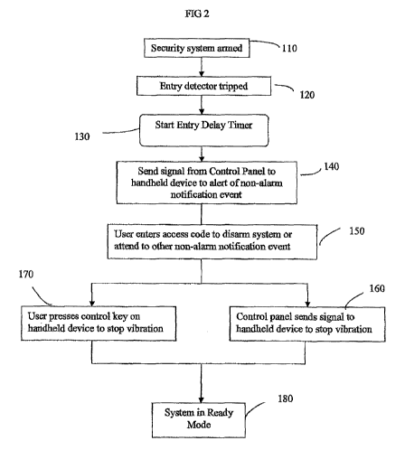
[0024] Fig. 2 is a flow chart illustrating an exemplary
operation of security system 10 utilizing the personal device
19 to notify a user of a qualified event, for example system
disarming before expiration of an entry delay. Of course, the
12
CA 02750768 2011-07-26
WO 2010/096918 PCT/CA2010/000254
personal device 19 may be utilized to alert a hearing impaired
user of other qualified events including, but not limited to,
exit delay, alarm time out after occurrence of an alarm event,
system malfunctions (communicator link faults, low battery,
loss of system power, etc.), zone chime control, and
activation of programmable outputs (e.g. garage door
activation), etc.
[0025] In particular, when a person enters the premises
wherein the security system is armed at step 110, the
associated detection device 181...18N, typically one or more door
contacts (e.g. 18N), is activated or tripped at step 120. Once
activated, the detection device transmits a signal to control
panel 20. Keypad 25 which is usually located near an
entry/exit door receives a signal from control panel 20 to
initiate an audible alert (e.g. warning beeps) to notify the
entering person to disarm system 10. Control panel 20
provides an entry delay period at step 130 for the person
entering the premises to enter an access code to disarm the
system. The duration of this entry delay period is stored in
memory 35 and may range from 30 seconds to more than a minute.
[0026] However, for a user that is hearing impaired, these
audible alarms would previously have gone unnoticed. Control
panel 20 sends a signal to personal device 19 at step 140.
The personal device vibrates in response to the received
signal. Upon vibrational alert, the user may enter the unique
13
CA 02750768 2011-07-26
WO 2010/096918 PCT/CA2010/000254
access code via keypad 25 to disarm system 10 (or attend to
other qualified event) at step 150. After disarming, control
panel 20 sends a signal to the personal device 19 stopping
vibration thereof at step 160. Alternatively, vibrational
notification may be stopped by the user pressing a control key
on device 19 at step 170. At step 180, the security system 10
is in ready mode.
[0027] The process described herein may be automated by,
for example, tangibly embodying a program of instructions in
memory 35 capable of being read by a machine which executes
these instructions. The CPU 34 is one example of such a
machine. The functions and process steps herein may be
performed automatically or wholly or partially in response to
user commands. A step performed automatically is performed in
response to one or more executable instructions or device
operations without user initiation of the activity.
[0028] While the present invention has been disclosed
with reference to certain embodiments, numerous modifications,
alterations and changes to the described embodiments are
possible without departing from the sphere and scope of the
present disclosure, as defined in the appended claims.
Accordingly, it is intended that the present invention not be
limited to the described embodiments, but that it has the full
scope defined by the language of the following claims, and
equivalents thereof.
14