Note: Descriptions are shown in the official language in which they were submitted.
CA 02750789 2011-07-26
PLASMA COATING SYSTEM AND METHOD FOR COATING OR
TREATING THE SURFACE OF A SUBSTRATE
The invention relates to a plasma coating plant and to a method for coating or
treating a surface of a substrate in accordance with the preamble of the inde-
pendent claim of the respective category.
From the numerous different processes of thermal spraying by means of
plasma coating plants a few are carried out in the vacuum region, this means
at a process pressure which is smaller than the air pressure of the environ-
ment. Such processes must naturally be carried out in evacuatable work
chambers. In this respect pressures of only a few hundred millibar or even
less
are necessary in the work chamber depending on the process.
On plasma spraying it is common to generate a plasma jet by heating a process
gas into which plasma jet the material required for the coating is typically
in-
troduced in powder form but also in fluid form, i.e. as gas or as liquid. In
par-
ticular, on introduction of gas or of liquid it is also known to carry out the
process of plasma spraying as a reactive process, i.e. to carry out the
process in
a comparable manner to a CVD process (chemical vapor deposition). In this
respect the fluid introduced into the hot plasma jet is modified such that the
desired substance for the coating only arises in the plasma jet, for example,
through the breaking open of bonds or the dissection of molecules. The intro-
duction of hexamethyldisiloxane (HMDSO) as a reactive substance to generate
a silicon oxide layer on the substrate, e.g. a wafer is an example for this.
CA 02750789 2011-07-26
2
A known problem in these vacuum processes is that the plasma jet, which
moves through the evacuated work chamber, leads to a suction effect in the
region of the nozzle of the plasma jet. If a gas or a liquid is introduced
into the
plasma jet for a reactive process, powder particles or particles can arise
through the modification. This can have the effect that particles - in
particular
at the boundary of the plasma jet - are deflected and move back in the direc-
tion of the nozzle and are then sucked back into the plasma jet through the
sucking effect. Such "recycled" particles or powder particles which are not
mol-
ten or sufficiently plastified generally lead to undesired faults in the
coating
generated on the substrate.
This problem also arises for processes in which a powder is introduced into
the
plasma jet. For example, non-molten or only partially molten and/or plastified
powder particles are moved back in the direction of the nozzle in the same way
as described above and are then sucked into the plasma jet. Also these powder
particles or particles lead to undesired contaminations on the substrate.
This invention aims to remedy this problem. For this reason it is an object of
the invention to propose a plasma coating plant and a method for coating or
treating the surface of a substrate in which the undesired intrusion of
particles
into the plasma jet is at least significantly reduced.
The subject matter of the invention satisfying this object in view of the
appara-
tus aspect and in view of the process engineering aspect are satisfied by the
independent claims of the respective category.
Thus, in accordance with the invention a plasma coating plant for coating or
treating the surface of a substrate is proposed, having a work chamber which
CA 02750789 2011-07-26
3
can be evacuated and into which the substrate can be placed, and having a
plasma torch for generating a plasma jet by heating a process gas, wherein the
plasma torch has a nozzle through which the plasma jet can exit the plasma
torch and can extend along a longitudinal axis into the work chamber, wherein
a mechanical limiting apparatus is provided downstream of the nozzle in the
work chamber, which mechanical limiting apparatus extends along the longi-
tudinal axis and protects the plasma jet against an unwanted lateral intrusion
of particles.
This limiting apparatus marks out the hot fast plasma jet with respect to the
colder, calmer, i.e. essentially current-free vacuum and thereby prevents that
particles are laterally sucked into the hot plasma jet in an undesired manner
from the vacuum region. In this respect "lateral" and/or "from the side" means
at an angle to or perpendicular to the longitudinal axis A.
The expansion of the plasma jet perpendicular to the longitudinal axis is lim-
ited by the limiting apparatus.
Thereby the plasma jet is surrounded and/or enclosed by the limiting appara-
tus so that no particles can arrive in the plasma jet from the side in an unde-
sired manner.
The limiting apparatus is preferably arranged directly downstream of the noz-
zle of the plasma torch, as the suction effect is strongest here and thus the
in-
trusion of particles is most probable here.
Advantageously, the limiting apparatus is configured as a tube, in particular
as a metallic tube.
CA 02750789 2011-07-26
4
In accordance with a preferred embodiment, the limiting apparatus is config-
ured as a cylindrical tube whose diameter is at most the ten-fold of the diame-
ter of the nozzle at its outlet opening in particular is at most the five-fold
of the
diameter of the nozzle.
An injection apparatus is preferably further provided to inject a reactive
fluid
into the plasma jet for carrying out reactive processes.
A possible design is present when the injection apparatus includes a ring-
shaped injection nozzle which is arranged in the limiting apparatus.
In accordance with a preferred embodiment a substrate holder for holding a
substrate is provided, wherein the limiting apparatus extends over at least 80
% of the distance between the nozzle and the substrate holder, preferably over
at least 90 % of the distance. The plasma jet is essentially protected against
contamination over its overall length from the nozzle of the plasma torch up
to
a substrate through this measure.
Furthermore, a method for coating or treating the surface of a substrate by
means of a plasma coating plant is proposed by the invention in which the
substrate is placed into a work chamber, the work chamber is evacuated to a
pressure of less than one bar, a plasma jet is generated by means of a plasma
torch by heating a process gas, which plasma jet exits the plasma torch
through a nozzle and can extend along a longitudinal axis in the work cham-
ber, wherein the plasma jet is protected against an unwanted lateral intrusion
of particles by a mechanical limiting apparatus which extends along the longi-
tudinal axis.
CA 02750789 2011-07-26
The widening of the plasma jet perpendicular to the longitudinal axis down-
stream of the nozzle is limited in the work chamber through the mechanical
limiting apparatus.
5 Preferably a reactive fluid is injected into the plasma jet by means of an
injec-
tion apparatus for carrying out reactive processes.
It is a preferred measure, also from a process engineering point of view, when
the plasma jet is protected by the limiting apparatus over at least 80 % of
its
length between the nozzle and the substrate, preferably over at least 90 % of
its length.
The method in accordance with the invention is suitable, in particular for
such
processes in which the process pressure in the work chamber is at most 100
mbar on coating, preferably at most 50 mbar and especially at most 30 mbar.
The danger of the unwanted recirculation and/or the unwanted suction of par-
ticles from the vacuum region into the plasma jet is namely especially pro-
nounced, in particular for low process pressures. Such particles, which can be
present, e.g. as molecules, free radicals or as other very small particles -
also in
the nanometer region - have an increased free path length in vacuum at low
process pressures so that the probability increases that such particles
intrude
the plasma jet and/or are sucked into this. At atmospheric pressure or even
higher process pressures such particles would be directly decelerated as a
rule
as soon as they laterally leave the plasma jet.
Further advantageous measures and embodiments result from the dependent
claims.
CA 02750789 2011-07-26
6
In the following the invention will be explained in detail both in view of the
apparatus aspect and also in view of the process engineering aspect with refer-
ence to embodiments and with reference to the drawing. In the schematic
drawing, not drawn to scale, there is shown:
Fig. 1 an embodiment of a plasma coating plant in accordance
with the invention,
Fig. 2 a view of the coating plant of Fig. 1,
Fig. 3 a section through the coating apparatus along the sec-
tional line 111-111 of Fig. 2,
Fig. 4 a top view onto the limiting apparatus from the viewing
direction IV of Fig. 2, and
Fig. 5 a variant for the embodiment from Fig. 1.
In the following the invention will be explained with reference to an example
particularly relevant for practice, namely with reference to a reactive plasma
spray process. In this respect a liquid or a gas-like starting material is
intro-
duced into the plasma jet. The molecules or components of the fluid starting
material are modified by the high energies of the plasma jet, for example, by
the splitting of bonds, the splitting of components etc., whereby the desired
components for the coating arise. Such processes are also comparable to CVD
processes in principle, for which reason they are sometimes referred to as
reac-
tive thermal CVD process. The so-called low pressure plasma spraying (LPPS)
and the low pressure plasma spraying - thin film-method (LPPS-TF) are espe-
cially suitable for this kind of a method.
CA 02750789 2011-07-26
7
It is naturally understood, however, that the invention is by no means re-
stricted to the this reactive plasma spray processes. It is suitable in an
analo-
gous equal manner for all plasma spray processes which are carried out in
vacuum, i.e. at a process pressure which is smaller than the surrounding air
pressure. As the initially mentioned problem of recirculation of powder parti-
cles and particles arises in these vacuum plasma spray processes, which
should be satisfied by the invention or at least be reduced by the invention.
In
particular the invention is also suitable for such vacuum plasma spray proc-
esses in which a powder-shaped starting material is introduced into the
plasma jet.
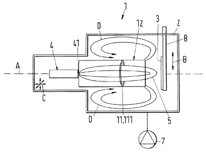
A schematic illustration of an embodiment of a plasma coating plant in accor-
dance with the invention, which is referred to totally with the reference nu-
meral 1, is shown in Fig. 1. The plasma coating plant 1 includes a work cham-
ber 2 having a plasma torch 4 for generating a plasma jet 5 by heating a proc-
ess gas. The plasma jet 5 exits through a nozzle 41 of the plasma torch 4 and,
in the operating state, widens along the longitudinal axis A. A controlled
pump
apparatus 7 is further provided which is connected to the work chamber 2 to
set the process pressure in the work chamber 2. A substrate holder 8 for hold-
ing a substrate 3 is provided in the work chamber 2 which can be movably de-
signed at least in one direction perpendicular to the longitudinal axis A, as
is
indicated by the double arrow B in Fig. 1. Through this the substrate 3 can be
moved perpendicular to the longitudinal axis A so that different regions of
the
substrate 3 can be gradually subjected to the plasma jet 5. Additionally or al-
ternatively hereto the substrate holder 8 can be configured such that the sub-
strate can be rotated during the treatment or coating if required.
CA 02750789 2011-07-26
8
The plasma torch 4 is also preferably arranged on a two-axis or a three-axis
displacement holder as is indicated by the arrows C in Fig. 1, so that the
rela-
tive position of the plasma torch 4 and thereby the relative position of the
noz-
zle 41 to the substrate 3 can be changed in two or three dimensions. In
particu-
lar the distance from the nozzle 41 to the substrate 3 can be changed.
With regard to further details of the design of the plasma spray plant 1 and
in
particular with regard to the process parameter regions and the injection into
the plasma jet 5 one is referred to the European patent application no.
08154091.6 of the same applicant at this point in time.
The liquid and/or gas-shaped starting material which is injected into the
plasma jet 5 on reactive plasma spraying can be introduced into the plasma jet
5 at different positions, for example in the nozzle 41 or upstream directly in
front of the nozzle 41 or together with the process gas in the axial
direction, i.e.
in the direction of the longitudinal axis A or also through an injection
appara-
tus 11 which is arranged further away downstream of the nozzle. Naturally,
also a combination of these variants is possible. In particular with regard to
the introduction of fluid media into the plasma jet 5 reference is made to EP-
A-
1 895 818 of the same applicant as well as to the previously cited European
patent application no. 08154091.6 of the same applicant.
In accordance with the invention a mechanical limiting apparatus 12 is pro-
vided in the work chamber 2 which extends along the longitudinal axis A and
protects the plasma jet 5 against an unwanted lateral intrusion of particles.
Furthermore, the widening of the plasma jet perpendicular to the longitudinal
axis A is limited hereby, the hot plasma jet is marked out with respect to the
colder vacuum region. In the present embodiment, the limiting apparatus is
configured as a cylindrical tube which extends in the direction of the longitu-
CA 02750789 2011-07-26
9
dinal axis A and runs coaxially to the longitudinal axis A. The limiting
appara-
tus 12 is preferably manufactured from a metallic material, in particular a
metal or an alloy.
The recirculation of particles or of powder particles is efficiently prevented
through the limiting apparatus as is indicated by the arrows D in Fig. 1. It
is
thereby prevented that the particles moving backwards laterally - i.e. at an
angle to or perpendicular to the longitudinal axis A - can intrude the plasma
jet in the direction of the nozzle 41 through the sucking effect of the plasma
jet
5. The quality of the coating manufactured on the substrate can be signifi-
cantly improved through this measure.
The limiting apparatus 12 preferably starts directly downstream of the nozzle
41. In dependence on the construction type it can also bound at the nozzle 41.
It is further preferred when the limiting apparatus 12 extends over at least
80
%, preferably over at least 90 % of the distance between the nozzle 41 and the
substrate 3 as the plasma jet is essentially protected over its overall length
between the nozzle 41 and the substrate 3 in this way. Particles can no longer
intrude in an undesired manner from the side, i.e. at an angle to or perpen-
dicular to the longitudinal axis from the vacuum region into the plasma jet 5.
This protection of the plasma jet 5 is also particularly important when - as
is
the case for the embodiment described here - the injection apparatus 11 is pro-
vided further downstream of the nozzle 41.
The respective dimensions of the limiting apparatus 12 depend on the specific
case of application and can be optimized for this. The limiting apparatus 12
should preferably be dimensioned such that it completely surrounds the
plasma jet with regard to the lateral direction - i.e. perpendicular to the
longi-
CA 02750789 2011-07-26
tudinal axis A - this means in the region of the limiting apparatus 12 the
plasma jet should run essentially completely within the limiting apparatus 12.
On the one hand, the diameter of the limiting apparatus 12 is not allowed to
be
too small and/or its clear width perpendicular to the longitudinal axis A
should
5 not be too small, as then the thermal energy transfer from the plasma jet 5
onto the limiting apparatus 12 is too strong and can damage the latter. On the
other hand, the diameter of the limiting apparatus 12 and/or its clear width
perpendicular to the longitudinal axis A cannot be so large that the limiting
apparatus 12 no longer represents an actual limitation for the lateral
widening
10 (perpendicular to the longitudinal axis A) of the plasma jet, for example,
the
danger would then arise that an undesired recirculation of particles arises
within the limiting apparatus.
The limiting apparatus is not essential for the shaping of the plasma jet or
for
the guiding of the plasma jet as the shape or form of the plasma jet is
substan-
tially determined by the pressure conditions and energy conditions as well as
the gas flows. The limiting apparatus bounds the hot plasma jet against the
cool vacuum.
The suitable diameter and/or the clear width of the limiting apparatus thereby
depend on the plasma jet and in particular on its lateral widening which it
would have without the limiting apparatus. Thus, for example, the lateral
widening of the plasma jet is larger the lower the process pressure is in the
work chamber and the larger the plasma power is. It is possible for the person
of ordinary skill in the art to adapt the dimensions of the limiting apparatus
for each case of application.
In practice diameters of at least 5 to 10 cm and up to 50 cm are especially
suit-
able for cylindrical tube-like limiting apparatuses 12.
CA 02750789 2011-07-26
11
Naturally it is not necessary that the limiting apparatus 12 is configured as
a
cylindrical tube, but also other shapes of cross-sections such as rectangular,
multi-angular or oval or other curvatures are possible. It can also be advanta-
geous when the limiting apparatus 12 changes its cross-sectional area in the
direction of the longitudinal axis A.
The Figs. 2 to 4 show the limiting apparatus 12 in more detail. Fig. 2 shows a
side view of the limiting apparatus 12 of Fig. 1. The limiting apparatus 12 is
configured as a metallic cylindrical tube 12 which extends in the direction of
the longitudinal axis A and has a diameter E. The tube is laterally provided
with a slot 121 which allows a monitoring of the plasma jet during operation
and, for example, can also serve for the reception of sensors. Holding
elements
122 are provided for stabilization.
The slot 121 further serves for the reception of a ring-shaped injection
nozzle
111 which is part of the injection apparatus 11 by means of which the reactive
fluid is introducible into the plasma jet. With regard to this ring nozzle 111
one
is in turn again referred to the already cited European patent application no.
08154091.6 of the same applicant.
Fig. 3 shows a section through the limiting apparatus along the sectional line
III-III in Fig. 2. In particular also the ring-shaped injection nozzle 111 can
be
recognized here.
Fig. 4 shows a top view onto the limiting apparatus 12 from the viewing direc-
tion IV in Fig. 2 and shows an inlet opening 123 of the limiting apparatus 12.
CA 02750789 2011-07-26
12
It is understood that for such vacuum processes in which no fluid is
introduced
into the plasma jet 5, but, for example, a powder one can do without the injec-
tion apparatus 11 and/or the ring-shaped injection nozzle 111.
Finally, Fig. 5 also shows, in an analogous illustration to Fig. 1, a variant
for
the embodiment of the plasma coating plant 1. In contrast to Fig. 1, the ring-
shaped injection nozzle is provided outside of the limiting apparatus 12 in
this
variant so that it surrounds the limiting apparatus 12. It is understood that
at
least a gap or a nozzle-shaped connection opening must be provided through
which the fluid is introducible into the plasma jet.
In an embodiment of the method in accordance with the invention, the manu-
facture and application of a thin SiO,{ layer by means of a reactive thermal
low
pressure plasma is explained in detail. A commercially available plasma torch
having a power for thermal plasma spraying can be used for the manufacture,
for example a plasma torch having three cathodes and a cascaded anode
equipped with water cooling. A plasma torch especially suitable for this, is
dis-
tributed by the applicant under the name TriplexPro. Argon, a mixture of ar-
gon and hydrogen or argon and helium can be used as a plasma gas and the
reactive components which are injected into the plasma jet can, for example,
be
composed of a mixture of gas-shaped hexamethyldisiloxane (HMDSO) with
oxygen. The oxygen proportion in the HMDSO/02 mixture is typically about 2
% to 3 % with regard to the gas flow. To achieve a higher gas exploitation the
reactive component is injected into the plasma jet 5 by means of the ring-
shaped injection nozzle 111. The distance between the substrate 3 and the in-
jection nozzle 111 amounts to approximately 77 cm. The distance of the nozzle
41 of the plasma torch 4 from the substrate amounts to approximately 1 m, the
process pressure in the work chamber is 0.2 mbar up to 1 mbar, in particular
CA 02750789 2011-07-26
13
approximately 0.5 mbar and the power supplied to the plasma torch is 8 kW up
to 16 kW. The oxygen flow amounts to approximately 3.4 liters per minute.
In this manner high quality SiO. layers, for example, of 2 gm thickness, but
also having a thickness smaller than or equal to 10 to 20 gm can be applied.
The deposition rate on a 30 cm x 30 cm large substrate lies at typically 10
nm/s
or higher, wherein an increased gas exploitation can be achieved with regard
to the supplied HMDSO gas. The SiO, layers are characterized by a high pu-
rity. In particular the milky look of the coating on the substrate 3 which is
fre-
quently recognizable without the limiting apparatus 11 can no longer be seen
and/or is significantly reduced.