Note: Descriptions are shown in the official language in which they were submitted.
CA 02751001 2011-07-28
PCT/EP2010/050374 - 1 -
200816011AT
Method and system for producing pig iron or fluid steel pre-
products
The invention relates to a method and a plant for the
production of pig iron or liquid steel semi-finished products,
metal-containing, in particular iron oxide-containing, batch
materials and, if appropriate, aggregates being at least
partially reduced in a reduction zone by means of a reduction
gas, subsequently being introduced into a smelting zone and
being smelted along with the supply of carbon carriers, in
particular coke and/or coal, and oxygen-containing gas and
along with the formation of the reduction gas, the formed
reduction gas being supplied to the reduction zone and reacted
there and being drawn off, if appropriate after purification,
as export gas.
It is known from the prior art that ultrafinely particulate
materials, such as, for example, carbon carriers, can be
introduced into smelting assemblies by injection by means of
injector gases. In this way, for example, pulverulent coals can
be introduced, for example, into a blast furnace or else into a
melt-down gasifier by means of an injector gas and an injector.
The disadvantage of this is that separate injector gases, such
as nitrogen, air or natural gas, have to be used, which
increase the inert gas volume in the process, particularly in
the case of additional internal gas recirculation, or entail
high operating costs (for natural gas, power).
An object of the invention, therefore is to make available a
method and a plant which avoid such disadvantages during the
introduction of ultrafinely particulate carbon carriers.
This object is achieved by means of the method according to the
invention, as claimed in claim 1, and by means of the plant as
claimed in claim 10.
CA 02751001 2011-07-28
PCT/EP2010/050374 - la -
200816011AT
By virtue of the method according to the invention, at least
part of the export gas, after a separation of 002r is utilized
for the introduction of pulverulent carbon carriers into
CA 02751001 2011-07-28
PCT/EP2010/050374 - 2 -
200816011AT
the smelting zone. Consequently, the quantity of reduction gas
which is drawn off as top gas from the reduction assembly and,
after purification, is present as export gas can be reduced or
the fraction of export gas which is utilized in the method can
be increased. The quantity of export gas which is used in the
method as circulation gas, that is to say is delivered anew to
the method, can likewise be reduced, since, instead of a
propellant gas, such as, for example, nitrogen, customary in
conventional methods, a process-specific gas is employed, with
the result that the circulated gas quantity is reduced.
Consequently, the energy (for example, power for compression)
required for conveying the export gas in the method can be
reduced, since substantially fewer inert gas constituents are
present in the process gases and therefore there is a
substantially lower energy demand for the compression, heating
and cooling of the process gases. The fraction of export gas
which cannot be utilized in the process likewise diminishes
and, moreover, considerable quantities of injector gas can be
saved, and therefore the operating costs of a plant for pig
iron production can be reduced. A further advantage is that the
reduction gas or circulation gas is not contaminated by the
propellant gas and therefore the reduction potential is also
not reduced. Furthermore, by reduction gas, from which CO2 is
to be separated, being introduced as propellant gas, the
initial introduction of energy via the oxygen nozzles or
tuyeres can be increased, with the result that reduction agents
in the form of coke or coal can be saved.
According to an advantageous refinement of the method according
to the invention, the product gas is combined in at least one
mixing chamber with the pulverulent carbon carriers, if
appropriate together with a conveying gas, and is then
introduced into the smelting zone. The product gas leads to a
considerable rise in the flow velocity at which the pulverulent
carbon carriers are introduced into the smelting zone. The
pulverulent carbon carriers can be introduced
CA 02751001 2011-07-28
PCT/EP2010/050374 - 3 -
200816011AT
into the mixing chamber by means of a conveying gas. By the
product gas being supplied, the pulverulent carbon carriers are
accelerated and are introduced into the smelting zone at higher
velocity. Due to this rise in the injection velocity, for
example, blockages caused by slag or damage caused by pig iron
injectors can be avoided. Introduction to the smelting zone can
be controlled in a directed manner or adapted to the operating
parameters via the pressure and product gas quantity or via the
conveying gas quantity.
According to an especially advantageous refinement of the
method according to the invention, the introduction of the
product gas and of the pulverulent carbon carriers, if
appropriate together with a conveying gas, into the smelting
zone takes place together with an oxygen-rich gas. The
pulverulent carbon carriers are used as energy carriers and for
the formation of reduction gas. For this purpose, it is
advantageous to add oxygen-rich gas immediately during
introduction, in order thereby to allow combustion and
therefore an introduction of energy. It is advantageous, for
example, to provide the hot blast air or oxygen-enriched hot
blast air required in the smelting zone as oxygen-rich gas and
to introduce it together with the pulverulent carbon carrier
and, if appropriate, with a conveying gas into the smelting
zone.
According to a further advantageous refinement of the method
according to the invention, the product gas, the pulverulent
carbon carriers, if appropriate the conveying gas, and the
oxygen-rich gas are injected together first into a tuyere or
into an oxygen nozzle and then into the smelting zone. Tuyeres
are devices which are customary in blast furnaces and via which
the hot, in particular oxygen-rich gas can be introduced into
the smelting zone. Oxygen nozzles are devices which are found
in smelt-reduction plants and which introduce oxygen-containing
gas having high 02 contents, preferably above 90% 02, into the
CA 02751001 2011-07-28
PCT/EP2010/050374 - 3a -
200816011AT
smelting zone of a smelting assembly, such as, for example, a
melt-down gasifier. These are mostly arranged annularly around
CA 02751001 2011-07-28
PCT/EP2010/050374 - 4 -
200816011AT
the smelting zone, so that a uniform introduction of the gas is
achieved. Advantageously, the abovementioned gases and the
pulverulent carbon carriers can be injected together into the
smelting zone, an intimate intermixing of the gases with the
pulverulent carbon carriers taking place.
According to a particular refinement of the method according to
the invention, the export gas is compressed and/or cooled
before treatment in the 002 separation device. By virtue of
these measures, on the one hand, the operating parameters
advantageous for 002 separation can be set and, on the other
hand, the pressure and temperature of the product gas can be
influenced.
According to a suitable refinement of the method according to
the invention, the 002-rich gas separated in the 002 separation
device is discharged as tail gas and is intermediately stored,
in particular together with export gas from the reduction zone.
The tail gas has a mostly highly fluctuating composition, and
therefore its calorific value, too, is not constant. Due to
intermediate storage, the properties of the tail gas can be
compensated. By excess export gas, which is not used as product
gas, being admixed, export gas can first be stored together
with tail gas and subsequently be made available for external
uses, such as, for example, for thermal utilization.
According to an advantageous refinement of the method according
to the invention, the 002-rich gas separated in the 002
separation device, as tail gas, and/or export gas from the
reduction zone are/is at least partially burnt in a heating
device for the purpose of heating the product gas. As a result
of combustion, the energy content of the tail gas and/or of the
export gas can be utilized, and therefore a cost-effective
heating of the export gas can be achieved. The exhaust
occurring during combustion is discharged and, if appropriate,
subjected to purification.
CA 02751001 2011-07-28
PCT/EP2010/050374 - 5 -
200816011AT
According to a further advantageous refinement of the method
according to the invention, the heated product gas is
introduced into the reduction zone and/or the smelting zone.
The fraction of export gas which remains in the method and can
be reused as circulation gas in the reduction zone and in the
smelting zone or as product gas in the smelting zone can
therefore be markedly increased.
According to an advantageous refinement of the method according
to the invention, the reduction gas drawn off from the
reduction zone is subjected to a dry dedusting and/or wet
purification. Since the drawn-off reduction gas has a
considerable fraction of dust load or fine solid particles, it
is advantageous first to provide purification, in which case
dry or wet purification treatments, but also combinations of
these, are possible. The purified drawn-off reduction gas may
be used according to the invention as export gas or delivered
for further applications, such as, for example, for thermal
utilization.
The plant according to the invention for the production of pig
iron or liquid steel semi-finished products comprises a
reduction assembly, in which metal oxide-containing, in
particular iron oxide-containing, batch materials and, if
appropriate, aggregates can be at least partially reduced by
means of a reduction gas, and a smelting assembly, into which
the at least partially reduced batch materials or the
aggregates can be introduced and smelted along with the supply
of carbon carriers, in particular coke and/or coal, and oxygen-
containing gas and along with the formation of the reduction
gas. The reduction gas formed in the smelting assembly can be
supplied to the reduction zone, reacted there and drawn off, if
appropriate after purification, as export gas. The plant
comprises, further, a CO2 separation device for separating CO2
from the export gas and for forming a product gas. The CO2
separation device is connected via a product gas line to at
CA 02751001 2011-07-28
PCT/EP2010/050374 - 5a -
200816011AT
least one introduction device for the introduction, in
particular injection, of pulverulent carbon carriers into the
CA 02751001 2011-07-28
PCT/EP2010/050374 - 6 -
200816011AT
smelting assembly. By means of the 002 separation device, 002
and preferably also residual water vapor (H2O), which are
disadvantageous for the smelting process or the generation of
reduction gas taking place during this and for the reduction in
the reduction zone, can be separated, so that a high-grade
product gas with a high fraction of reducing components, such
as carbon monoxide (CO) and hydrogen (H2), is set. Pulverulent
carbon carriers occur in large quantity in a multiplicity of
metallurgical methods, such as, for example, also in the
handling of lumpy coals.
The possibility of processing carbon carriers of this type is
therefore a substantial economic benefit. Likewise, due to the
renewed utilization of the reduction gas drawn off from the
reduction assembly, the overall efficiency of the pig iron
production method can be improved, so that, for example, the
entire quantity of carbon carriers per tonne of produced pig
iron can be reduced. By the product gas being utilized for
introducing pulverulent carbon carriers into the smelting
assembly, it is possible to manage without the otherwise
customary injection gas, such as, for example, nitrogen, liquid
gas or natural gas. Consequently, on account of the lower inert
gas fraction, the quantity of process gas is reduced overall,
so that even smaller plants for gas treatment or gas conduction
become possible.
According to an alternative refinement of the apparatus
according to the invention, the introduction device has a
mixing chamber for mixing the product gas with pulverulent
carbon carriers and, if appropriate, conveying gas, the mixing
chamber being connected to the product gas line and to a
conveying line for the inward conveyance of the pulverulent
carbon carriers. First, the pulverulent carbon carriers are
introduced into the mixing chamber, and this may take place,
for example, by means of a conveying gas or else due to gravity
via the conveying line. By the product gas being added via the
CA 02751001 2011-07-28
PCT/EP2010/050374 - 6a -
200816011AT
product gas line, the injection velocity and injection energy
CA 02751001 2011-07-28
PCT/EP2010/050374 - 7 -
200816011AT
necessary for introduction are applied, so that the pulverulent
carbon carriers can be introduced into the smelting assembly.
The mixing chamber results in an intimate mixing between the
product gas and the pulverulent carbon carriers, so that a
uniform introduction becomes possible.
In one possible variant of the apparatus according to the
invention, the introduction device has an introduction line
which connects the mixing chamber to at lest one nozzle. By
means of the nozzle, a considerable rise in the flow velocity
is obtained, so that even injection into a space with high
pressure, such as is the case in conventional smelting
assemblies, is possible. Moreover, the intimate intermingling
of the pulverulent carbon carriers is further increased, so
that a highly homogeneous distribution in the smelting assembly
becomes possible. By a plurality of mixing chambers and/or a
plurality of nozzles being provided, a uniform distribution of
the pulverulent carbon carriers in the smelting assembly can be
ensured.
According to an especially advantageous refinement of the
apparatus according to the invention, the introduction device
has a supply line for the introduction of oxygen-containing
gas. The pulverulent carbon carriers can be introduced together
with the oxygen-containing gas, an immediate combustion of the
pulverulent carbon carriers and of the product gas or a
gasification of the pulverulent carbon carriers upon entry into
the smelting assembly being achieved.
According to a further possible refinement of the apparatus
according to the invention, the supply line and the
introduction line are merged in the nozzle. The nozzle
consequently forms a virtually homogeneous nozzle jet which
enters the smelting assembly. It is therefore not necessary to
provide separate devices for introducing the oxygen-containing
gas and for the pulverulent carbon carriers. These can be
CA 02751001 2011-07-28
PCT/EP2010/050374 - 7a -
200816011AT
combined. For the introduction of the pulverulent carbon
carriers,
CA 02751001 2011-07-28
PCT/EP2010/050374 - 8 -
200816011AT
therefore, those can be utilized which are already provided in
any case for introducing the oxygen-containing gas.
According to an especially advantageous refinement of the
apparatus according to the invention, the nozzle is a tuyere of
a blast furnace or an oxygen nozzle of a smelting assembly.
Tuyeres serve for the introduction of mostly hot blast air into
the smelting assembly. Oxygen nozzles are devices which are
found in smelt-reduction plants and which introduce oxygen-
containing gas having high 02 contents, preferably above 90%
02, into the smelting zone of a smelting assembly. For this
purpose, mostly annular devices are provided, in order to allow
as uniform an introduction of the hot blast air as possible.
Instead of hot air, however, it is also possible to inject
oxygen-rich gas, for example having an oxygen content >90%,
into the smelting assembly. The oxygen-rich gas and the
pulverulent carbon carriers can consequently be injected
together into the smelting assembly. This refinement ensures an
especially effective reaction of the pulverulent carbon
carriers, so that these can be utilized especially effectively
as energy carriers and for the formation of reduction gas.
According to an advantageous refinement of the apparatus
according to the invention, the reduction assembly is designed
as the shaft of a blast furnace or as a reduction shaft or as a
fluidized bed assembly or as a group of series-connected
fluidized bed assemblies and the smelting assembly is designed
as the lower part of a blast furnace or as a melt-down
gasifier. Consequently, a very broad group of metal oxide-
containing or iron oxide-containing batch materials and
aggregates can be processed, while the reduction assembly can
be adapted, for example, to the grain size and composition of
the metal oxide-containing or iron oxide-containing batch
materials or to the type of lumpy carbon carriers. Likewise, by
the selection of the smelting assembly, the plant and method
can be coordinated accurately with the metal oxide-containing
CA 02751001 2011-07-28
PCT/EP2010/050374 - 8a -
200816011AT
or iron oxide-containing batch materials to be processed.
CA 02751001 2011-07-28
PCT/EP2010/050374 - 9 -
200816011AT
In one possible variant of the apparatus according to the
invention, a purification device, in particular dry
purification and/or wet purification, is provided in a top gas
outlet line for the outlet of reduction gas from the reduction
assembly. By means of the purification device, the dust load
and, for example, fine solid particles discharged with the
reduction gas from the reduction assembly are separated. In
addition to dry purification, such as, for example, a dust bag,
hot gas cyclone, fabric filter or hot gas filter, wet
purification, such as, for example, an annular gap scrubber or
a Venturi scrubber, may also be provided. Further, a
combination of the above purification plants is also possible.
The purified reduction gas drawn off the reduction assembly may
be utilized according to the invention as export gas or be
delivered for further applications or utilizations.
According to an advantageous refinement of the apparatus
according to the invention, the purification device is
connected by means of an export gas line to the 002 separation
device, a compressor and/or at least one cooler being arranged
in the export gas line. The export gas is first compressed and
then cooled, a substantial fraction of water vapor (H2O) also
being condensed and separated, so that optimal conditions for
002 separation can be set.
According to an advantageous refinement of the apparatus
according to the invention, a heating device for the heating
product gas before the introduction of the latter into the
reduction assembly and/or into the smelting assembly is
provided, the heating device being capable of being heated as a
result of the at least partial combustion of tail gas and/or of
export gas. Consequently, the product gas, which is to be
introduced into the smelting assembly and/or into the reduction
assembly can be thermally adapted correspondingly. As a result
of the combustion of tail gas or of export gas in the heating
device, the product gas can be heated particularly cost-
CA 02751001 2011-07-28
PCT/EP2010/050374 - 9a -
200816011AT
effectively. The heated product gas can be introduced via lines
which connect the heating device
CA 02751001 2011-07-28
PCT/EP2010/050374 - 10 -
200816011AT
to the smelting assembly and to the reduction assembly.
Introduction to the smelting assembly may also take place via
the introduction device according to the invention.
The invention is explained in more detail below, by way of
example and unrestrictively, with reference to figures 1 and 2.
Figure 1 shows a plant according to the invention with a blast
furnace.
Figure 2 shows a detail of the introduction device.
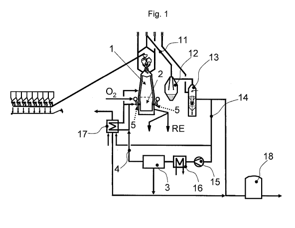
Figure 1 shows the plant according to the invention with a
blast furnace for the production of pig iron RE. The lower part
of the blast furnace forms a smelting assembly 2 with a
smelting zone, and the shaft of the blast furnace forms a
reduction assembly 1 with a reduction zone. The reduction gas
drawn off from the reduction assembly 1 has already been
reacted in the reduction zone. This means that metal oxide-
containing or iron oxide-containing batch materials and, if
appropriate, aggregates can be at least partially reduced by
means of the reduction gas in the reduction assembly 1, the
spent reduction gas being drawn off as top gas. The at least
partially reduced metal oxide-containing or iron oxide-
containing batch materials are introduced into the smelting
zone in which the formation of the reduction gas also takes
place.
For a further utilization of top gas, it is initially mostly
necessary to provide gas purification. This may advantageously
take place in two stages by means of dry purification 12 and by
means of following wet purification 13. These purification
devices are arranged in the top gas outlet line 11. Wet
purification 13 is connected via an export gas line 14 to a C02
separation device 3. This may be operated, for example, by the
pressure swing or vacuum pressure swing adsorption method.
Mostly, a compressor 15 and, following this, a cooling device
CA 02751001 2011-07-28
PCT/EP2010/050374 - 10a -
200816011AT
16, such as, for example a water cooler, are provided in the
export gas line 14, so that the temperature of the
CA 02751001 2011-07-28
PCT/EP2010/050374 - 11 -
200816011AT
export gas can be set in a directed manner for the CO2
separation, and a large part of the water vapor contained in
the export gas can be condensed and separated. In CO2
separation, a C02-rich gas, the tail gas, is separated, and a
product gas is formed which has high fractions of reducing
components, such as, for example, hydrogen and carbon monoxide.
Figure 2 shows the introduction device 5 in detail. The product
gas can be introduced into at least one mixing chamber 6 via
the product gas line 4. Via a conveying line 7, pulverulent
carbon carriers, such as, for example, pulverulent coal, are
conveyed into the mixing chamber 6 by means of a conveying gas,
such as, for example, nitrogen, and are supplied to a nozzle 9
via an introduction line 8 by means of the product gas. The
supply line 10, via which oxygen-rich gas can be introduced,
also issues into the nozzle 9. Consequently, the oxygen-rich
gas, the conveying gas, the product gas and the pulverulent
carbon carriers are introduced or injected together into the
smelting assembly. Advantageously, a multiplicity of nozzles
may be provided which may be arranged in such a way that they
inject directly into the tuyere or oxygen nozzle of a smelting
assembly, such as, for example, a blast furnace.
The introduction line 8 may be designed as an injection lance
which may also comprise the mixing chamber 6. Further, the
introduction line 8 may also be designed as a separate
injection duct which issues into the nozzle 9. The nozzle 9 may
form a tuyere of a blast furnace or an oxygen nozzle of a
smelting assembly, such as, for example, a melt-down gasifier.
Preferably, the supply line 10 and the introduction line 8 are
merged at the tip of the injection lance which projects into
the tuyere or into the oxygen nozzle or at an injection duct in
the tuyere or in the oxygen nozzle. Both configurations utilize
the tuyere or the oxygen nozzle which constitute
CA 02751001 2011-07-28
PCT/EP2010/050374 - 12 -
200816011AT
known devices, so that the method according to the invention or
the apparatus can also be implemented on existing plants.
In addition, a heating device 17 may be provided, in which a
heating of at least part of the product gas can take place as a
result of an at least partial combustion of tail gas from the
002 separation device 3 and/or of export gas. This heated part
of the product gas can be introduced into the reduction
assembly 1 or into the smelting assembly 2.
Excess export gas or else tail gas can be stored in a gas
accumulator 18, an equalization of the composition of these
gases taking place. This is necessary, since the composition of
the tail gas from a pressure swing or vacuum pressure swing
adsorption method fluctuates very sharply, thus also resulting
in sharp fluctuations in the calorific value. The gas mixture
may subsequently be used, for example, for thermal utilization.
CA 02751001 2011-07-28
PCT/EP2010/050374 - 13 -
200816011AT
List of reference symbols
1 Reduction assembly
2 Smelting assembly
3 002 separation device
4 Product gas line
Introduction device
6 Mixing chamber
7 Conveying line
8 Introduction line
9 Nozzle
Supply line
11 Top gas outlet line
12 Dry purification
13 Wet purification
14 Export gas line
Compressor
16 Cooling device
17 Heating device
18 Gas accumulator