Note: Descriptions are shown in the official language in which they were submitted.
CA 02751080 2016-05-31
METHOD AND APPARATUS FOR CONTROL OF FLUID TEMPERATURE AND
FLOW
DESCRIPTION OF THE INVENTION
Field of the Invention
[001] Materials, components, and methods consistent with the present
invention are directed to the fabrication and use of micro-scale channels with
a fluid,
where the temperature and flow of the fluid is at least partially controlled
through the
geometry of the channel and the configuration of at least a portion of the
wall of the
channel and the constituent particles that make up the fluid.
Background of the Invention
[002] A volume of fluid, such as air, may be characterized by a temperature
and pressure. When considered as a collection of constituent particles,
comprising, for
example, molecules of oxygen and nitrogen, the volume of fluid at a given
temperature
may also be characterized as a distribution of constituent particle speeds.
[003] This distribution may characterized, generally, by an average speed
which is understood to bear a relationship with the temperature of the fluid
(as a gas).
[004] Accordingly, the internal thermal energy of a fluid provides a source
of
energy for applications related to heating, cooling, and the generation of
fluid flow. One
manner of exploiting the internal thermal energy of a fluid, such as a gas,
has been
described in U.S. Patent Nos. 7,008,176 and 6,932,564.
22930302.1
CA 02751080 2011-07-28
WO 2010/039868
PCT/US2009/059079
[005] Where the device for exploiting the internal thermal energy of a
fluid, such as a gas, operates by selecting the constituent particles of the
fluid
based upon the use of moving parts to select the particles direction of
movement or its velocity, there exists a need for a method and device that can
control fluid flow and temperature, but that is not based upon such moving
parts.
[006] It is accordingly a primary object of the invention to provide a
solution for systems and methods that benefit from cooling, heating, and/or
flow control of a fluid but that operate upon principles that do not rely upon
moving parts.
[007] This is achieved by the manufacture and use of systems that
utilize one or more micro-scale channels (a "micro channel") that are
configured to accommodate the flow of a fluid, and where the walls of the
micro channel and the constituent particles in the fluid are configured such
that collisions between the constituent particles and the walls of the micro
channel are substantially specular.
SUMMARY OF THE INVENTION
[008] An exemplary micro channel consistent with the present
invention is configured with an inflow opening and an oufflow opening ¨
which are in fluid communication with each other.
[009] As used herein the "cross-section" of a micro channel refers to
a characteristic area of the micro channel that is substantially perpendicular
to
the direction defined by the general flow of a fluid through the micro
channel.
[010] As used herein the "throat" of a micro channel refers to that
portion of the micro channel which exhibits a local minima in its cross-
section.
Note that there may be multiple throats associated with one micro channel.
[011] In one embodiment consistent with the present invention, the
inflow opening of a micro channel is configured to be the throat of the micro
channel, and the walls of the micro channel are configured to present a micro
channel with a generally continuously increasing cross section along the
2
CA 02751080 2011-07-28
WO 2010/039868
PCT/US2009/059079
direction of flow of the fluid. In such an exemplary embodiment, (where, for
example the fluid is air) the inflow opening is preferably 100 pm^2 and may be
anywhere in the range 0.01 prnA2 to 500 prnA2. Moreover, the outflow
opening is preferably 3000 prnA2 and may be anywhere in the range 0.1 pmA2
to 50,000 pm^2. The length of the walls of the micro channel (i.e., the linear
distance between the inflow opening and the outflow opening of the micro
channel) is preferably 30 mm and may be anywhere in the range 0.01 mm to
meters. In another embodiment consistent with the present invention, the
dimensions of the inflow opening and the outflow opening (and the
dimensions of the cross section as a function of length) may be reversed from
that just discussed. For example, the inflow opening is preferably 3000 prnA2
and may be anywhere in the range 0.1 pm^2 to 50,000 pm^2, and the outflow
opening is preferably 100 prnA2 and may be anywhere in the range 0.01 pm^2
to 500 pm"2.
[012] In another embodiment consistent with the present invention,
the inflow opening of a micro channel is configured to be the throat of the
micro channel, and the walls of the micro channel are configured to present a
micro channel with a sharp increase in the cross section adjacent to the
throat, and then a substantially static cross section along the direction of
flow
of the fluid. In such an exemplary embodiment, (where, for example the fluid
is air) the inflow opening is preferably 100 pm^2 and may be anywhere in the
range 0.01 prnA2 to 500 pm^2. An exemplary length of such an inflow
opening, prior to expanding to a larger, substantially constant, opening, may
be approximately 500 pm. Moreover, the outflow opening is preferably 3000
prnA2 and may be anywhere in the range 0.1 prnA2 to 50,000 pm^2. The
length of the walls of the micro channel (i.e., the linear distance between
the
inflow opening and the outflow opening of the micro channel) is preferably 30
mm and may be anywhere in the range 0.01 mm to 50 meters. In another
embodiment consistent with the present invention, the dimensions of the
inflow opening and the outflow opening (and the dimensions of the cross
section as a function of length) may be reversed from that just discussed. For
3
CA 02751080 2011-07-28
WO 2010/039868 PCT/US2009/059079
example, the inflow opening is preferably 3000 prnA2 and may be anywhere in
the range 0.1 prnA2 to 50,000 pm^2, and the outflow opening is preferably 100
pm^2 and may be anywhere in the range 0.01 prnA2 to 500 pm^2.
[013] In another embodiment consistent with the present invention,
both the inflow opening and the outflow opening of a micro channel are
configured to be throats of the micro channel (i.e., present local minima in
the
cross section), and the walls of the micro channel are configured to present a
micro channel with a generally continuously increasing cross section along
the direction of flow of the fluid to a maximum point ¨ preferably mid-way
between the inflow opening and the outflow opening ¨ and then to present a
micro channel with a generally continuously decreasing cross section along
the direction of flow of the fluid to a local minimum point at the outflow
opening. In such an exemplary embodiment, (where, for example the fluid is
air) the inflow opening and the outflow opening are preferably 100 pm^2 and
may be anywhere in the range 0.01 prnA2 to 500 prn^2. The maximum of the
cross section between the inflow opening and the outflow opening is
preferably 3000 pm^2 and may be anywhere in the range 0.1 pm^2 to 50,000
pm"2. The length of the walls of the micro channel (i.e., the linear distance
between the inflow opening and the outflow opening of the micro channel) is
preferably 30 mm and may be anywhere in the range 0.02 mm to 100 meters.
[014] In yet another embodiment consistent with the present
invention, both the inflow opening and the outflow opening of a micro channel
are configured to be throats of the micro channel, and the walls of the micro
channel are configured present a micro channel with a sharp increase in the
cross section adjacent to the throat at the inflow opening, a substantially
static
cross section along the direction of flow of the fluid, and then a sharp
decrease in the cross section adjacent to the throat at the outflow opening.
In
such an exemplary embodiment, (where, for example the fluid is air) the inflow
opening and the outflow opening are preferably 100 pm^2 and may be
anywhere in the range 0.01prnA2 to 500 pm"2. The maximum of the cross
section between the inflow opening and the outflow opening is preferably
4
CA 02751080 2011-07-28
WO 2010/039868
PCT/US2009/059079
3000 pm^2 and may be anywhere in the range 0.1 pm^2 to 50,000 pm^2.
The length of the walls of the micro channel (i.e., the linear distance
between
the inflow opening and the outflow opening of the micro channel) is preferably
30 mm and may be anywhere in the range 0.02 mm to 100 meters. An
exemplary length of such an inflow opening and outflow opening (prior to their
expansion to the larger, substantially constant, cross section), may be
approximately 500 pm.
[015] In another embodiment consistent with the present invention,
any one of the micro channel segments described above (a first micro
channel segment) may be configured to be in fluid communication with
another micro channel segment (a second micro channel segment), such as
configuring the outflow opening of the first micro channel segment to be
direct
in fluid communication with the inflow opening of a second micro channel
segment. Moreover, the first micro channel segment and the second micro
channel segment may be configured to present cross sections that exhibit
similar or substantially similar walls shapes and dimensions as a function of
length of the micro channel, and similar or substantially similar throat
dimensions.
[016] Further still, in another embodiment consistent with the present
invention, any one of the micro channel segments described above (a first
micro channel segment) may be configured to present a micro channel that is
substantially parallel to another micro channel segment (a second micro
channel segment), such as configuring the inflow openings of the first micro
channel segment and the second micro channel segment to be in fluid
communication with each other, and the outflow openings of the first micro
channel segment and the second micro channel segment to be in fluid
communication with each other. Moreover, the first micro channel segment
and the second micro channel segment may be configured to present cross
sections that exhibit similar or substantially similar walls shapes and
dimensions as a function of length of the micro channel, and similar or
substantially similar throat dimensions.
CA 02751080 2011-07-28
WO 2010/039868
PCT/US2009/059079
[017] In addition, the manipulation of the flow and temperature of a
volume of fluid, where the fluid comprises molecules, allows for the
population
of molecular vibrational through the enhanced heating of a volume of a fluid.
Where such vibrationally-excited molecules are allowed to relax, then
methods and systems consistent with the present invention allow for the
creation and manipulation of electromagnetic radiation emitted thereby.
[018] Further still, the manipulation of the flow and temperature of a
volume of fluid, provides for an abundance of practical applications ranging
from heating and cooling, refrigeration, electricity generation, coherent and
non-coherent light emission, gas pumping, plasma and particle beam
production, particle beam acceleration, chemical processes, and others.
[019] Additional objects and advantages of the invention will be set
forth in part in the description which follows, and in part will be obvious
from
the description, or may be learned by practice of the invention. The objects
and advantages of the invention will be realized and attained by means of the
elements and combinations particularly pointed out in the appended claims.
[020] It is to be understood that both the foregoing general
description and the following detailed description are exemplary and
explanatory only and are not restrictive of the invention, as claimed.
[021] The accompanying drawings, which are incorporated in and
constitute a part of this specification, illustrate an embodiment of the
invention
and together with the description, serve to explain the principles of the
invention.
BRIEF DESCRIPTION OF THE DRAWINGS
[022] Figure 1 is view of a cross section of one embodiment
consistent with the present invention;
[023] Figure 2 is alternative view of three cross sectional shapes
consistent with the present invention and the embodiments depicted, for
example, in FIGS. 1, 4, 5, and 6;
6
CA 02751080 2011-07-28
WO 2010/039868
PCT/US2009/059079
[024] Figure 3 is an exemplary illustration of a specular collision
consistent with the present invention;
[025] Figure 4 depicts another embodiment of a micro channel
consistent with the present invention;
[026] Figure 5 depicts another embodiment of a micro channel
consistent with the present invention;
[027] Figure 6 depicts yet another embodiment consistent with the
present invention;
[028] Figure 7 depicts an embodiment consistent with the present
invention utilizing a serial configuration of the embodiments consistent with
FIGS. 1 and 4;
[029] Figure 8 depicts an embodiment consistent with the present
invention utilizing a serial configuration of the embodiments consistent with
FIGS. 5 and 6;
[030] Figure 9 depicts an embodiment consistent with the present
invention utilizing a serial configuration of the embodiment consistent with
FIG. 7;
[031] Figure 10 depicts an embodiment consistent with the present
invention utilizing a serial configuration of the embodiment consistent with
FIG. 8;
[032] Figure 11 depicts an embodiment consistent with the present
invention utilizing a parallel configuration of the embodiment consistent with
FIG. 1;
[033] Figure 12 depicts an embodiment consistent with the present
invention utilizing a parallel configuration of the embodiment consistent with
FIG. 4;
[034] Figure 13 depicts an embodiment consistent with the present
invention utilizing a parallel configuration of the embodiment consistent with
FIG. 5;
7
CA 02751080 2011-07-28
WO 2010/039868
PCT/US2009/059079
[035] Figure 14 depicts an embodiment consistent with the present
invention utilizing a parallel configuration of the embodiment consistent with
FIG. 6;
[036] Figure 15 depicts an embodiment consistent with the present
invention utilizing a parallel configuration of the embodiment consistent with
FIG. 7;
[037] Figure 16 depicts an embodiment consistent with the present
invention utilizing a parallel configuration of the embodiment consistent with
FIG. 8;
[038] Figure 17 depicts an embodiment consistent with the present
invention utilizing a parallel configuration of the embodiment consistent with
FIG. 9; and
[039] Figure 18 depicts an embodiment consistent with the present
invention utilizing a parallel configuration of the embodiment consistent with
FIG. 10.
DESCRIPTION OF THE EMBODIMENTS
[040] Reference will now be made in detail to the present
embodiment (exemplary embodiment) of the invention, characteristics of
which are illustrated in the accompanying drawings. Wherever possible, the
same reference numbers will be used throughout the drawings to refer to the
same or like parts.
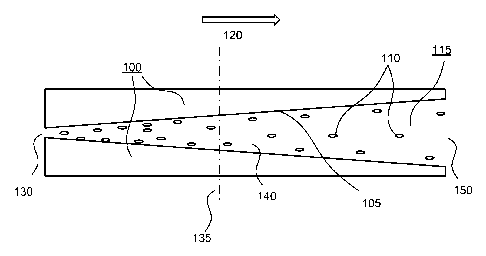
[041] FIG. 1 depicts a view of an exemplary embodiment consistent
with the present invention. Micro channel 100 includes inflow opening 130
and outflow opening 150. Fluid 115, comprising constituent particles 110,
flows through micro channel 100 in direction 120. Wall 105 of micro channel
100 is proximal to the flow of fluid 115. The view associated with FIG. 1 is
that of a cross sectional slice of micro channel 100 consistent with the
present
invention. Other exemplary cross sectional views of micro channel 100
consistent with the present invention are depicted in FIG. 2, and represent
exemplary views consistent with slice 135 (shown in FIG. 1). For example the
8
CA 02751080 2011-07-28
WO 2010/039868
PCT/US2009/059079
cross section of inflow opening 130, region 140, and outflow opening 150 may
be any one of square 101, circle 102, rectangle 103, or any other shape
associated with a bounded two-dimensional figure.
[042] Considering FIG. 1 again, the flow of fluid 115 in direction 120
through micro channel 100 may be induced through the use of a pressure
differential between inflow opening 130 and outflow opening 150. Moreover,
wall 105 and constituent particles 110 are configured such that collisions
between constituent particles 110 and wall 105 that are internal in micro
channel 100 (where the internal region is represented generally by region
140) are substantially specular. Specular collisions are depicted in an
exemplary fashion in FIG. 3 in more detail.
[043] FIG. 3 depicts a portion of FIG. 1 in more detail. Specifically,
arrow 325 represents a velocity component of constituent particle 110 before
constituent particle 110 collides with wall 105. Normal 305 represents an axis
that is perpendicular to the plane defined by wall 105. Arrow 335 represents a
velocity component of constituent particle 110 after constituent particle 110
collides with wall 105. As used herein, a specular collision between
constituent particle 110 and wall 105 is a collision in which the velocity
component of constituent particle 110 parallel to the plane of wall 105 is
substantially the same before and after the collision. Moreover, during a
specular collision, the speed of constituent particle 110 associated with the
velocity component perpendicular to the plane of wall 105 may be
substantially the same before and after the collision. One skilled in the art
should appreciate that the term "specular collision" as used herein should not
be interpreted to apply to elastic collisions only. Rather, because there will
be
a transfer of energy (on the average) between wall 105 of the micro channel
and a plurality constituent particles 110, it is understood that any one
particular specular collision between constituent particle 110 and wall 105
may increase or decrease the kinetic energy of constituent particle 110
relative to the kinetic energy it possessed prior to the collision. For
example,
if there is a transfer of energy from wall 105 to constituent particle 110,
then
9
CA 02751080 2011-07-28
WO 2010/039868
PCT/US2009/059079
one would expect that the acute angle between constituent particle 110 and
the plane parallel to wall 105 would be larger after the collision than before
the
collision. Likewise, if there is a transfer of energy from constituent
particle
110 to wall 105, then one would expect that the acute angle between
constituent particle 110 and the plane parallel to wall 105 would be smaller
after the collision than before the collision. Furthermore, where the
temperature of the fluid comprising a plurality of constituent particles is
different from the temperature of the wall, there is expected to be a transfer
of
internal energy from the fluid to the wall, or from the wall to the fluid
(depending upon which is at the higher temperature). Where the collisions
between a plurality of constituent particles 110 and wall 105 are
substantially
specular as used herein, the transfer of energy from fluid 115 to wall 105 or
from wall 105 to fluid 115 is expected to occur predominantly through the
average change in the speed of constituent particle 110 associated with the
change in its velocity component perpendicular to the plane of wall 105 during
the collision. One should also appreciate that such a change in the velocity
component of constituent particle 110 during the collision will change the
overall speed of constituent particle 110 as a result of the collision
process.
[044] Returning to FIG. 1, fluid 115 that enters micro channel 100
through inflow opening 130 may be induced to flow to outflow opening 150
through the use of a pressure differential between inflow opening 130 and
outflow opening 150, where the pressure of fluid 115 at inflow opening 130 is
higher than the pressure of fluid 115 at outflow opening. Where the
temperature of fluid 115 at inflow opening 130 is 7-1, then constituent
particles
110 (prior to entering region 140) may be represented by a distribution of
speeds, the average speed of which is proportional to temperature.
[045] Where the throat of inflow opening is small (for example,
anywhere from 0.01pm^2 to 500 prnA2 where the fluid is air), then constituent
particle 110 moving through inflow opening 130 into region 140 will generally
exhibit a velocity that has its component parallel to direction 120 larger
than
its component perpendicular to direction 120. Consequently, fluid 115
CA 02751080 2011-07-28
WO 2010/039868
PCT/US2009/059079
acquires a flow velocity that is predominantly parallel to direction 120. The
kinetic energy that is associated with the flow of fluid 115 in direction 120
is
drawn from the internal thermal energy of fluid 115, which was at T1 before it
entered inflow opening 130. Conservation of energy dictates that, because a
portion of the original thermal energy of fluid 115 at T1 has been converted
to
kinetic energy of flow for fluid 115, the temperature of fluid 115 (in a frame
that is stationary with the velocity of flow) in region 140 is lower than T1,
which
we will designate as T2. Where T2 is also less than the temperature of wall
105 (which we will designate as Tw) of micro channel 100, then fluid 115 in
region 140 will act to cool the material comprising micro channel 100.
[046] Micro channel 100, consistent with an embodiment of the
present invention is configured to enhance the effect this temperature change
has on fluid 115 in at least three ways. Specifically, where wall 105 and
constituent particles 110 are configured such that collisions between wall 105
and constituent particles 110 are substantially specular, then such collisions
¨ which are a means of transferring energy between wall 105 and fluid 115
¨will have a minimal effect on the overall flow of fluid 115. In other words,
where the collision between constituent particle 110 and wall 105 is such that
the velocity of constituent particle 110 is equally likely to be in any
direction
away from wall 105 (i.e., a non-specular collision), then a plurality of such
collisions will have the effect of slowing down the flow of fluid 115, which
will
also likely have the effect of raising the internal temperature of fluid 115
in
region 140. Micro channel 100, consistent with an embodiment of the present
invention, is configured to enhance the effect of cooling by selectively
avoiding the effect of non-specular collisions.
[047] In addition, because wall 105 of micro channel 100 is
configured to present a generally increasing cross sectional area through
which the flow of fluid 115 occurs, the specular scattering of constituent
particle 110 off of wall 105 will convert a portion of the velocity component
which was perpendicular to direction 120 to a component parallel to direction
120.
11
CA 02751080 2011-07-28
WO 2010/039868
PCT/US2009/059079
[048] Moreover, because micro channel 100 is engineered to be
small (La, with an internal surface area that may be as small as
approximately 3e-11 mA2 per linear micron to 6e-10 mA2 per linear micro in a
preferred embodiment), then the ratio of the surface area presented by wall
105 to a given volume of fluid 115 in region 140 is relatively large (i.e.,
where
the volume of fluid 115 enclosed by the above surface is approximately 8e-17
mA3 per linear micron to 3e-15 mA3 per linear micron). Because the surface
area presented by wall 105 to a volume of fluid 115 is a primary means of
energy exchange between wall 105 and fluid 115, then this maximizes the
overall energy exchange interaction between fluid 115 and micro channel 100.
[049] FIG. 4 depicts a view of another exemplary embodiment
consistent with the present invention. Micro channel 400 includes inflow
opening 430 and outflow opening 450. Fluid 415, comprising constituent
particles 410, flows through micro channel 400 in direction 420. Wall 405 of
micro channel 400 is proximal to the flow of fluid 415. The view associated
with FIG. 4 is that of a cross sectional slice of micro channel 400 consistent
with the present invention. As described previously in connection with micro
channel 100, other exemplary cross sectional views of micro channel 400
consistent with the present invention are depicted in FIG. 2, and represent
exemplary views consistent with slice 135 (in this instance, shown in FIG. 4).
For example the cross section of inflow opening 430, region 440, and outflow
opening 450 may be any one of square 101, circle 102, rectangle 103, or any
other shape associated with a bounded two-dimensional figure.
[050] Considering FIG. 4 again, the flow of fluid 415 in direction 420
through micro channel 400 may be induced through the use of a pressure
differential between inflow opening 430 and outflow opening 450. Moreover,
wall 405 and constituent particles 410 are configured such that collisions
between constituent particles 410 and wall 405 that are internal in micro
channel 400 (where the internal region is represented generally by region
440) are substantially specular.
12
CA 02751080 2011-07-28
WO 2010/039868
PCT/US2009/059079
[051] Fluid 415 that enters micro channel 400 through inflow opening
430 may be induced to flow to outflow opening 450 through, for example,
work performed on fluid 415 at inflow opening 430 to generate a flow in
direction 420 in the direction of outflow opening 450 (and where, for example,
the pressure of fluid 415 at inflow opening 430 is higher than the pressure of
fluid 415 at outflow opening). Where the temperature of fluid 415 at inflow
opening 430 is T1, then constituent particles 410 (prior to entering region
440)
may be represented by a distribution of speeds, the average speed of which is
proportional to temperature.
[052] In the embodiment considered in FIG. 4, we consider fluid 415
with an induced flow parallel to direction 420. Consequently, constituent
particles 410 in fluid 415 will exhibit more of a velocity component in
direction
420 (relative to micro channel 400) than in directions perpendicular to
direction 420.
[053] Unlike micro channel 100, however, wall 405 of micro channel
400 is configured to present a generally decreasing cross sectional area
through which flow occurs. In this instance, accordingly, the specular
scattering of constituent particle 410 off of wall 405 will convert a portion
of
the velocity component which was parallel to direction 420 to a component
perpendicular to direction 420. Such a conversion from flow energy to internal
kinetic energy of fluid 415 will tend to raise the temperature of fluid 415.
This
will become more focused near oufflow opening 450. Accordingly, near this
region, micro channel 400 is configured to have transferred much of the flow
energy associated with fluid 415 at inflow opening 430 into internal kinetic
energy of fluid 415.
[054] Under these circumstances, one may desire to thermally
isolate that portion of micro channel 400. For example, one may configure a
portion of micro channel 400 proximal to outflow opening such that it does not
transmit thermal energy to other portions of micro channel 400. This
thermally isolated region is depicted in FIG. 4 as region 455.
13
CA 02751080 2011-07-28
WO 2010/039868
PCT/US2009/059079
[055] In addition, where constituent particles 410 of fluid 415 are
molecules (and, for example, where fluid 415 is a gas), then certain
vibrational
states of constituent particles 410 may be populated as a result of the
increase in temperature that is achieved near outflow opening 450.
[056] Where such vibrationally-excited molecules subsequently pass
through outflow opening 450, then there is a probability that these
vibrationally-excited molecules will emit electromagnetic radiation in order
to
relax to a lower vibrational state. Note also that micro channel 400 may be
used to create a population inversion in vibrational states, which is useful
for
lasing applications, among a collection of such vibrationally-excited
molecules
that pass through outflow opening 450.
[057] FIG. 5 depicts another view of an exemplary embodiment
consistent with the present invention. Micro channel 500 includes inflow
opening 530 and outflow opening 550. Fluid 515, comprising constituent
particles 510, flows through micro channel 500 in direction 520. Wall 505 of
micro channel 500 is proximal to the flow of fluid 515. The view associated
with FIG. 5 is that of a cross sectional slice of micro channel 500 consistent
with the present invention. Other exemplary cross sectional views of micro
channel 500 consistent with the present invention are depicted in FIG. 2, and
represent exemplary views consistent with slice 135 (shown in FIG. 5). For
example the cross section of inflow opening 530 and outflow opening 550
may be any one of square 101, circle 102, rectangle 103, or any other shape
associated with a bounded two-dimensional figure.
[058] The flow of fluid 515 in direction 520 through micro channel
500 may be induced through the use of a pressure differential between inflow
opening 530 and outflow opening 550. Moreover, wall 505 and constituent
particles 510 are configured such that collisions between constituent
particles
510 and wall 505 that are internal in micro channel 500 are substantially
specular.
[059] Fluid 515 that enters micro channel 500 through inflow opening
530 may be induced to flow to outflow opening 550 through the use of a
14
CA 02751080 2011-07-28
WO 2010/039868
PCT/US2009/059079
pressure differential between inflow opening 530 and oufflow opening 550,
where the pressure of fluid 515 at inflow opening 530 is higher than the
pressure of fluid 515 at outflow opening. Where the temperature of fluid 515
at inflow opening 530 is Ti, then constituent particles 510 (prior to entering
micro channel 500) may be represented by a distribution of speeds, the
average speed of which is proportional to temperature.
[060] Where the throat of inflow opening is small (for example,
anywhere from 0.01prnA2 to 500 prnA2 where the fluid is air, and where the
length of the throat along the direction of the flow is approximately 500 pm),
then constituent particle 510 moving through inflow opening 530 into micro
channel 500 will generally exhibit a velocity that has its component parallel
to
direction 520 larger than its component perpendicular to direction 520.
Consequently, fluid 515 acquires a flow velocity that is predominantly
parallel
to direction 520. The kinetic energy that is associated with the flow of fluid
515 in direction 520 is drawn from the internal thermal energy of fluid 515,
which was at T1 before it entered inflow opening 530. Conservation of energy
dictates that, because a portion of the original thermal energy of fluid 515
at
T/ has been converted to kinetic energy of flow for fluid 515, the temperature
of fluid 515 (in a frame that is stationary with the velocity of flow) in
region 540
is lower than Ti, which we will designate as T2. Where T2 is also less than
the
temperature of wall 505 (which we will designate as Tw) of micro channel 500,
then fluid 515 in micro channel 500 will act to cool the material comprising
micro channel 500.
[061] Micro channel 500, consistent with an embodiment of the
present invention is also configured to enhance the effect this temperature
change has on fluid 515 in at least three ways. Specifically, where wall 505
and constituent particles 510 are configured such that collisions between wall
505 and constituent particles 510 are substantially specular, then such
collisions ¨ which are a means of transferring energy between wall 505 and
fluid 515 ¨ will have a minimal effect on the overall flow of fluid 515. In
other
words, where the collision between constituent particle 510 and wall 505 is
CA 02751080 2011-07-28
WO 2010/039868
PCT/US2009/059079
such that the velocity of constituent particle 510 is equally likely to be in
any
direction away from wall 505 (i.e., a non-specular collision), then a
plurality of
such collisions will have the effect of slowing down the flow of fluid 515,
which
will also likely have the effect of raising the internal temperature of fluid
515 in
region 540. Micro channel 500, consistent with an embodiment of the present
invention, is configured to enhance the effect of cooling by selectively
avoiding the effect of non-specular collisions.
[062] In addition, because the mean free path between constituent
particles 510 in fluid 515 is generally increasing as a function of length
between inflow opening 530 and outflow opening 550, then it is believed that
the specular scattering of constituent particle 510 off of wall 505 as a
function
of length along micro channel 500 will also likely act to convert a portion of
the
velocity component which was perpendicular to direction 520 to a component
parallel to direction 520.
[063] Moreover, because micro channel 500 is engineered to be
small (i.e., with an internal surface area in the substantially constant
region
that may be as small as approximately 6e-10 mA2 per linear micron in a
preferred embodiment in a preferred embodiment), then the ratio of the
surface area presented by wall 505 to a given volume of fluid 515 in region
540 is relatively large (i.e., where the volume of fluid 115 enclosed by the
above surface is approximately 3e-15 mA3 per linear micron). Because the
surface area presented by wall 505 to a volume of fluid 515 is a primary
means of energy exchange between wall 505 and fluid 515, then this
maximizes the overall energy exchange interaction between fluid 515 and
micro channel 500.
[064] FIG. 6 depicts a view of another exemplary embodiment
consistent with the present invention. Micro channel 600 includes inflow
opening 630 and outflow opening 650. Fluid 615, comprising constituent
particles 610, flows through micro channel 600 in direction 620. Wall 605 of
micro channel 600 is proximal to the flow of fluid 615. The view associated
with FIG. 6 is that of a cross sectional slice of micro channel 600 consistent
16
CA 02751080 2011-07-28
WO 2010/039868
PCT/US2009/059079
with the present invention. As described previously in connection with micro
channel 100, other exemplary cross sectional views of micro channel 600
consistent with the present invention are depicted in FIG. 2, and represent
exemplary views consistent with slice 135 (in this instance, shown in FIG. 6).
For example the cross section of inflow opening 630 and outflow opening 650
may be any one of square 101, circle 102, rectangle 103, or any other shape
associated with a bounded two-dimensional figure.
[065] The flow of fluid 615 in direction 620 through micro channel
600 may be induced through the use of a pressure differential between inflow
opening 630 and outflow opening 650. Moreover, wall 605 and constituent
particles 610 are configured such that collisions between constituent
particles
610 and wall 605 that are internal in micro channel 600 (where the internal
region is represented generally by region 640) are substantially specular.
[066] Fluid 615 that enters micro channel 600 through inflow opening
630 may be induced to flow to outflow opening 650 through, for example,
work performed on fluid 615 at inflow opening 630 to generate a flow in
direction 620 in the direction of outflow opening 650 (and where, for example,
the pressure of fluid 615 at inflow opening 630 is higher than the pressure of
fluid 615 at outflow opening). Where the temperature of fluid 615 at inflow
opening 630 is 7-1, then constituent particles 610 (prior to entering micro
channel 600) may be represented by a distribution of speeds, the average
speed of which is proportional to temperature.
[067] In the embodiment considered in FIG. 6, we consider fluid 615
with an induced flow parallel to direction 620. Consequently, constituent
particles 610 in fluid 615 will exhibit more of a velocity component in
direction
620 (relative to micro channel 600) than in directions perpendicular to
direction 620.
[068] Unlike micro channel 500, however, wall 605 of micro channel
600 is configured to present a sharply decreasing cross sectional area in the
vicinity of outflow opening 650. In this instance, accordingly, the specular
scattering of constituent particle 610 off of wall 605 will convert a portion
of
17
CA 02751080 2011-07-28
WO 2010/039868
PCT/US2009/059079
the velocity component which was parallel to direction 620 to a component
anti-parallel to direction 620. Such a conversion from flow energy to internal
kinetic energy of fluid 615 will tend to raise the temperature of fluid 615.
This
will become focused near outflow opening 650. Accordingly, near this region,
micro channel 600 is configured to have transferred much of the flow energy
associated with fluid 615 at inflow opening 630 into internal kinetic energy
of
fluid 615.
[069] Under these circumstances, one may desire to thermally
isolate that portion of micro channel 600. For example, one may configure a
portion of micro channel 600 proximal to outflow opening such that it does not
transmit thermal energy to other portions of micro channel 600. This
thermally isolated region is depicted in FIG. 6 as region 655.
[070] Where constituent particles 610 of fluid 615 are molecules
(and, for example, where fluid 615 is a gas), then certain vibrational states
of
constituent particles 610 may be populated as a result of the increase in
temperature that is achieved near outflow opening 650.
[071] Where such vibrationally-excited molecules subsequently pass
through outflow opening 650, then there is a probability that these
vibrationally-excited molecules will emit electromagnetic radiation in order
to
relax to a lower vibrational state. Note also that micro channel 600 may be
used to create a population inversion in vibrational states, which is useful
for
lasing applications, among a collection of such vibrationally-excited
molecules
that pass through outflow opening 650.
[072] FIG. 7 depicts a view of another exemplary embodiment
consistent with the present invention. Micro channel 700, consistent with an
embodiment of the present invention, is configured to utilize a linear
combination of the exemplary embodiments depicted in FIG. 1 and FIG. 4.
[073] Accordingly, the discussions relevant to the embodiments
depicted in FIGS. 1 and 4 are herein incorporated by reference.
[074] Micro channel 700 includes inflow opening 730 and outflow
opening 750. Fluid 715, comprising constituent particles 710, flows through
18
CA 02751080 2011-07-28
WO 2010/039868
PCT/US2009/059079
micro channel 700 in direction 720. Wall 705 of micro channel 700 is proximal
to the flow of fluid 715. The view associated with FIG. 7 is that of a cross
sectional slice of micro channel 700 similar to the views presented in FIGS. 1
and 4.
[075] Fluid 715 that enters micro channel 700 through inflow opening
730 may be induced to flow to oufflow opening 750 through the use of a
pressure differential between inflow opening 730 and oufflow opening 750,
where the pressure of fluid 715 at inflow opening 730 is higher than the
pressure of fluid 715 at outflow opening. Moreover, wall 705 and constituent
particles 710 are configured such that collisions between constituent
particles
710 and wall 705 that are internal in micro channel 700 are substantially
specular.
[076] Where the temperature of fluid 715 at inflow opening 730 is
then constituent particles 710 (prior to entering micro channel 700) may be
represented by a distribution of speeds, the average speed of which is
proportional to temperature.
[077] Where the throat of inflow opening is small (for example,
anywhere from 0.01prnA2 to 500 pm^2), then constituent particle 710 moving
through inflow opening 730 into micro channel 700 will generally exhibit a
velocity that has its component parallel to direction 720 larger than its
component perpendicular to direction 720. Consequently, fluid 715 initially
acquires a flow velocity that is predominantly parallel to direction 720. The
kinetic energy that is associated with the flow of fluid 715 in direction 720
is
drawn from the internal thermal energy of fluid 715, which was at 7-1 before
it
entered inflow opening 730. Conservation of energy dictates that, because a
portion of the original thermal energy of fluid 715 at 1-1 has been converted
to
kinetic energy of flow for fluid 715, the temperature of fluid 715 (in a frame
that is stationary with the velocity of flow) prior to midpoint 740 is lower
than
which we will designate as T2. Where T2 is also less than the temperature
of wall 705 between inflow opening 730 and midpoint 740 (which we will
designate as Tw) of micro channel 700, then fluid 715 in the region between
19
CA 02751080 2011-07-28
WO 2010/039868
PCT/US2009/059079
inflow opening 730 and midpoint 740 will act to cool the material comprising
micro channel 700.
[078] Micro channel 700, consistent with an embodiment of the
present invention is configured to enhance the effect this temperature change
has on fluid 715 in at least three ways. Specifically, where wall 705 and
constituent particles 710 are configured such that collisions between wall 705
and constituent particles 710 are substantially specular, then such collisions
¨which are a means of transferring energy between wall 705 and fluid 715
¨will have a minimal effect on the overall flow of fluid 715. In other words,
where the collision between constituent particle 710 and wall 705 is such that
the velocity of constituent particle 710 is equally likely to be in any
direction
away from wall 705 (i.e., a non-specular collision), then a plurality of such
collisions will have the effect of slowing down the flow of fluid 715, which
will
also likely have the effect of raising the internal temperature of fluid 715
in
region between inflow opening 730 and midpoint 740. Micro channel 700,
consistent with an embodiment of the present invention, is configured to
enhance the effect of cooling by selectively avoiding the effect of non-
specular
collisions in this region.
[079] In addition, because wall 705 of micro channel 700 is
configured to present a generally increasing cross sectional area between
inflow opening 730 and midpoint 740 through which the flow of fluid 715
occurs, the specular scattering of constituent particle 710 off of wall 705
will
convert a portion of the velocity component which was perpendicular to
direction 720 to a component parallel to direction 720.
[080] Moreover, because micro channel 700 is engineered to be
small (i.e., with an internal surface area that may be as small as
approximately 3e-11 m"2 per linear micron to 6e-10 mA2 per linear micron in a
preferred embodiment), then the ratio of the surface area presented by wall
705 to a given volume of fluid 715 in micro channel 700 is relatively large
(i.e.,
where the volume of fluid 115 enclosed by the above surface is approximately
8e-17 m"3 per linear micron to 3e-15 rnA3 per linear micron). Because the
CA 02751080 2011-07-28
WO 2010/039868
PCT/US2009/059079
surface area presented by wall 705 to a volume of fluid 715 is a primary
means of energy exchange between wall 705 and fluid 715, then this
maximizes the overall energy exchange interaction between fluid 715 and
micro channel 700.
[081] Considering micro channel 700 between midpoint 740 and
outflow opening 750, fluid 715 has an induced flow (that may be enhanced
through the cooling effect of wall 705 between inflow opening 730 and
midpoint 740) parallel to direction 720. Consequently, constituent particles
710 in fluid 715 in this region will exhibit more of a velocity component in
direction 720 (relative to micro channel 700) than in directions perpendicular
to direction 720.
[082] Unlike the region between inflow opening 730 and midpoint
740, however, wall 705 of micro channel 700 is configured to present a
generally decreasing cross sectional area through which flow occurs between
midpoint 740 and outflow opening 750. In this region, accordingly, the
specular scattering of constituent particle 710 off of wall 705 will convert a
portion of the velocity component which was parallel to direction 720 to a
component perpendicular to direction 720. Such a conversion from flow
energy to internal kinetic energy of fluid 715 will tend to raise the
temperature
of fluid 715. This will become more focused near outflow opening 750.
Accordingly, near this region, micro channel 700 is configured to have
transferred much of the flow energy associated with fluid 715 at midpoint 740
(which includes some of the energy associated with the cooling of wall 705
between inflow opening 730 and midpoint 740) into internal kinetic energy of
fluid 715.
[083] Under these circumstances, one may desire to thermally
isolate that portion of micro channel 700. For example, one may configure a
portion of micro channel 700 proximal to outflow opening such that it does not
transmit thermal energy to other portions of micro channel 700. This
thermally isolated region is depicted in FIG. 7 as region 755. In addition,
thermoelectric device 770 may be configured to extract the thermal energy
21
CA 02751080 2011-07-28
WO 2010/039868
PCT/US2009/059079
localized in region 755. Thermoelectric device 770 may be any such device
that is conventionally available, such as, without limitation, part 1261G-7L31-
04CQ commercially available from Custom Thermoelectric.
[084] Where constituent particles 710 of fluid 715 are molecules
(and, for example, where fluid 715 is a gas), then certain vibrational states
of
constituent particles 710 may be populated as a result of the increase in
temperature that is achieved near outflow opening 750.
[085] Where such vibrationally-excited molecules subsequently pass
through outflow opening 750, then there is a probability that these
vibrationally-excited molecules will emit electromagnetic radiation in order
to
relax to a lower vibrational state. Note also that micro channel 700 may be
used to create a population inversion in vibrational states, which is useful
for
lasing applications, among a collection of such vibrationally-excited
molecules
that pass through outflow opening 750.
[086] FIG. 8 depicts a view of another exemplary embodiment
consistent with the present invention. Micro channel 800, consistent with an
embodiment of the present invention, is configured to utilize a linear
combination of the exemplary embodiments depicted in FIG. 5 and FIG. 6.
[087] Accordingly, the discussions relevant to the embodiments
depicted in FIGS. 5 and 6 are herein incorporated by reference.
[088] Micro channel 800 includes inflow opening 830 and outflow
opening 850. Fluid 815, comprising constituent particles 810, flows through
micro channel 800 in direction 820. Wall 805 of micro channel 800 is proximal
to the flow of fluid 815. The view associated with FIG. 8 is that of a cross
sectional slice of micro channel 800 similar to the views presented in FIGS. 5
and 6.
[089] Fluid 815 that enters micro channel 800 through inflow opening
830 may be induced to flow to outflow opening 850 through the use of a
pressure differential between inflow opening 830 and outflow opening 850,
where the pressure of fluid 815 at inflow opening 830 is higher than the
pressure of fluid 815 at outflow opening. Moreover, wall 805 and constituent
22
CA 02751080 2011-07-28
WO 2010/039868
PCT/US2009/059079
particles 810 are configured such that collisions between constituent
particles
810 and wall 805 that are internal in micro channel 800 are substantially
specular.
[090] Where the temperature of fluid 815 at inflow opening 830 is 7-1,
then constituent particles 810 (prior to entering micro channel 800) may be
represented by a distribution of speeds, the average speed of which is
proportional to temperature.
[091] Where the throat of inflow opening is small (for example,
anywhere from 0.01prnA2 to 500 pm^2 where the fluid is air, and where the
length of the throat along the direction of the flow is approximately 500 pm),
then constituent particle 810 moving through inflow opening 830 into micro
channel 800 will generally exhibit a velocity that has its component parallel
to
direction 820 larger than its component perpendicular to direction 820.
Consequently, fluid 815 initially acquires a flow velocity that is
predominantly
parallel to direction 820. The kinetic energy that is associated with the flow
of
fluid 815 in direction 820 is drawn from the internal thermal energy of fluid
815, which was at 1-1 before it entered inflow opening 830. Conservation of
energy dictates that, because a portion of the original thermal energy of
fluid
815 at 1-1 has been converted to kinetic energy of flow for fluid 815, the
temperature of fluid 815 (in a frame that is stationary with the velocity of
flow)
prior to region 845 (discussed below) is lower than Th which we will designate
as T2. Where T2 is also less than the temperature of wall 805 between inflow
opening 830 and region 845 (which we will designate as TO of micro channel
800, then fluid 815 in the region between inflow opening 830 and region 845
will act to cool the material comprising micro channel 800.
[092] Micro channel 800, consistent with an embodiment of the
present invention is configured to enhance the effect this temperature change
has on fluid 815 in at least three ways. Specifically, where wall 805 and
constituent particles 810 are configured such that collisions between wall 805
and constituent particles 810 are substantially specular, then such collisions
¨ which are a means of transferring energy between wall 805 and fluid 815
23
CA 02751080 2011-07-28
WO 2010/039868
PCT/US2009/059079
- will have a minimal effect on the overall flow of fluid 815. In other words,
where the collision between constituent particle 810 and wall 805 is such that
the velocity of constituent particle 810 is equally likely to be in any
direction
away from wall 805 (i.e., a non-specular collision), then a plurality of such
collisions will have the effect of slowing down the flow of fluid 815, which
will
also likely have the effect of raising the internal temperature of fluid 815
in
region between inflow opening 830 and region 845. Micro channel 800,
consistent with an embodiment of the present invention, is configured to
enhance the effect of cooling by selectively avoiding the effect of non-
specular
collisions in this region.
[093] In addition, because the mean free path between constituent
particles 810 in fluid 815 is generally increasing as a function of length
between inflow opening 830 and region 845, then it is believed that the
specular scattering of constituent particle 810 off of wall 805 as a function
of
length along micro channel 800 will also likely act to convert a portion of
the
velocity component which was perpendicular to direction 820 to a component
parallel to direction 820.
[094] Moreover, because micro channel 800 is engineered to be
small (i.e., with an internal surface area that may be as small as
approximately 6e-10 mA2 per linear micron in a preferred embodiment), then
the ratio of the surface area presented by wall 805 to a given volume of fluid
815 in micro channel 800 is relatively large (i.e., where the volume of fluid
enclosed by the above surface area is approximately 3e-15 mA3 per linear
micron). Because the surface area presented by wall 805 to a volume of fluid
815 is a primary means of energy exchange between wall 805 and fluid 815,
then this maximizes the overall energy exchange interaction between fluid
815 and micro channel 800.
[095] Considering micro channel 800 in region 845 proximal to
outflow opening 850, fluid 815 has an induced flow (that may be enhanced
through the cooling effect of wall 805 between inflow opening 830 and region
845) parallel to direction 820. Consequently, constituent particles 810 in
fluid
24
CA 02751080 2011-07-28
WO 2010/039868
PCT/US2009/059079
815 in the region between inflow opening 830 and region 845 will exhibit more
of a velocity component in direction 820 (relative to micro channel 800) than
in
directions perpendicular to direction 820.
[096] Unlike the region between inflow opening 830 and region 845,
however, wall 855 of micro channel 800 is configured to present an abrupt
decrease in the cross sectional area through which flow occurs at outflow
opening 850. In region 845, accordingly, the specular scattering of
constituent particle 810 off of wall 855 and the subsequent collision between
constituent particles 810 in region 845 will convert a portion of the velocity
component which was parallel to direction 820 to a component perpendicular
to direction 820. Such a conversion from flow energy to internal kinetic
energy of fluid 815 will tend to raise the temperature of fluid 815. This is
indicated to occur in FIG. 8 in region 845, near outflow opening 850.
Accordingly, in region 845, micro channel 800 is configured to have
transferred much of the flow energy associated with fluid 815 between inflow
opening 830 and region 845 (which includes some of the energy associated
with the cooling of wall 805 between inflow opening 830 and region 845) into
internal kinetic energy of fluid 815.
[097] Under these circumstances, one may desire to thermally
isolate that portion of micro channel 800. For example, one may configure a
portion of micro channel 800 proximal to outflow opening such that it does not
transmit thermal energy to other portions of micro channel 800. This
thermally isolated region is depicted in FIG. 8 as region 855. In addition,
thermoelectric device 770 may be configured to extract the thermal energy
localized in region 855. As has been discussed, thermoelectric device 770
may be any such device that is conventionally available, such as, without
limitation, part 1261G-7L31-04CQ commercially available from Custom
Thermoelectric.
[098] Where constituent particles 810 of fluid 815 are molecules
(and, for example, where fluid 815 is a gas), then certain vibrational states
of
CA 02751080 2011-07-28
WO 2010/039868 PCT/US2009/059079
constituent particles 810 may be populated as a result of the increase in
temperature that is achieved near outflow opening 850.
[099] Where such vibrationally-excited molecules subsequently pass
through outflow opening 850, then there is a probability that these
vibrationally-excited molecules will emit electromagnetic radiation in order
to
,
relax to a lower vibrational state. Note also that micro channel 800 may be
used to create a population inversion in vibrational states, which is useful
for
lasing applications, among a collection of such vibrationally-excited
molecules
that pass through outflow opening 850.
[0100] FIG. 9 depicts a view of another exemplary embodiment
consistent with the present invention. Micro channel 900, consistent with an
embodiment of the present invention, is configured to utilize a linear
combination of the exemplary embodiment depicted in FIG. 7.
[0101] Accordingly, the discussion relevant to the embodiment
depicted in FIG. 7 is herein incorporated by reference.
[0102] Micro channel 900 includes inflow opening 930 and outflow
opening 950. Fluid 915 flows through micro channel 900 in direction 920.
Wall 905 of micro channel 900 is proximal to the flow of fluid 915. The view
associated with FIG. 9 is that of a cross sectional slice of micro channel 900
similar to the view presented in FIG. 7.
[0103] Fluid 915 that enters micro channel 900 through inflow opening
930 may be induced to flow to outflow opening 950 through the use of a
pressure differential between inflow opening 930 and outflow opening 950,
where the pressure of fluid 915 at inflow opening 930 is higher than the
pressure of fluid 915 at outflow opening. Moreover, wall 905 and the
constituent particles of fluid 915 are configured such that collisions between
the constituent particles and wall 905 that are internal in micro channel 900
are substantially specular.
[0104] As with the embodiment discussed in FIG. 7, one may desire to
thermally isolate those portions of micro channel 900 that may be heated by
fluid 915. In the embodiment depicted in FIG. 9, portions of micro channel
26
CA 02751080 2016-05-31
900 proximal to region 965 and to out flow opening 950 are configured such
that they do
not transmit thermal energy to other portions of micro channel 900. These
thermally
isolated regions are depicted in FIG. 9 as region 955. As discussed earlier,
thermoelectric device 770 may be configured to extract the thermal energy
localized in
region 955. Thermoelectric device 770 may be any such device that is
conventionally
available, such as, without limitation, part 1261G-7L31-04CQ commercially
available
from Custom Thermoelectric.
[0105] Also, as discussed earlier, where the constituent particles of
fluid 915
are molecules (and, for example, where fluid 915 is a gas), then certain
vibrational
states of the constituent particles may be populated as a result of the
increase in
temperature that is achieved near region 965 and outflow opening 950.
[0106] Where such vibrationally-excited molecules subsequently pass
through
region 965 and outflow opening 950, then there is a probability that these
vibrationally-
excited molecules will emit electromagnetic radiation in order to relax to a
lower
vibrational state. Photoelectric device 975 may be used to utilize the
electromagnetic
energy that is generated as a result of such electromagnetic emissions. In the
vicinity of
photoelectric device 975, micro channel 900 may be configured to be
transparent to the
emitted radiation.
[0107] FIG. 10 depicts a view of another exemplary embodiment consistent
with the present invention. Micro channel 1000, consistent with an embodiment
of the
present invention, is configured to utilize a linear combination of the
exemplary
embodiment depicted in FIG. 8.
[0108] Accordingly, the discussion relevant to the embodiment depicted
in
FIG. 8 is also relevant here.
[0109] Micro channel 1000 includes inflow opening 1030 and outflow
opening
1050. Fluid 1015 flows through micro channel 1000 in direction 1020. Wall 1005
of
micro channel 1000 is proximal to the flow of fluid 1015. The view associated
with FIG.
is that of a cross sectional slice of micro channel 1000 similar to the view
presented
in FIG. 8.
27
22930302.1
CA 02751080 2011-07-28
WO 2010/039868
PCT/US2009/059079
[0110] Fluid 1015 that enters micro channel 1000 through inflow
opening 1030 may be induced to flow to outflow opening 1050 through the
use of a pressure differential between inflow opening 1030 and outflow
opening 1050, where the pressure of fluid 1015 at inflow opening 1030 is
higher than the pressure of fluid 1015 at outflow opening. Moreover, wall
1005 and the constituent particles of fluid 1015 are configured such that
collisions between the constituent particles and wall 1005 that are internal
in
micro channel 1000 are substantially specular.
[0111] As with the embodiment discussed in FIG. 8, one may desire to
thermally isolate those portions of micro channel 1000 that may be heated by
fluid 1015. In the embodiment depicted in FIG. 10, portions of micro channel
1000 proximal to region 1065 and to out flow opening 1050 are configured
such that they do not transmit thermal energy to other portions of micro
channel 1000. These thermally isolated regions are depicted in FIG. 10 as
region 1055. As discussed earlier, thermoelectric device 770 may be
configured to extract the thermal energy localized in region 1055.
Thermoelectric device 770 may be any such device that is conventionally
available, such as, without limitation, part 1261G-7L31-04CQ commercially
available from Custom Thermoelectric.
[0112] Also, as discussed earlier, where the constituent particles of
fluid 1015 are molecules (and, for example, where fluid 1015 is a gas), then
certain vibrational states of the constituent particles may be populated as a
result of the increase in temperature that is achieved near region 1065 and
outflow opening 1050.
[0113] Where such vibrationally-excited molecules subsequently pass
through region 1065 and outflow opening 1050, then there is a probability that
these vibrationally-excited molecules will emit electromagnetic radiation in
order to relax to a lower vibrational state. Photoelectric device 975 may be
used to utilize the electromagnetic energy that is generated as a result of
such
electromagnetic emissions. In the vicinity of photoelectric device 975, micro
channel 1000 may be configured to be transparent to the emitted radiation.
28
CA 02751080 2011-07-28
WO 2010/039868
PCT/US2009/059079
[0114] FIG. 11 depicts a view of another exemplary embodiment
consistent with the present invention. Micro channel 1100, consistent with an
embodiment of the present invention, is configured to utilize a parallel
combination of the exemplary embodiment depicted in FIG. 1. Accordingly,
the discussion relevant to the embodiment depicted in FIG. 1 is herein
incorporated by reference. In the embodiment depicted in FIG. 11, fluid
enters through inflow openings 1130 and exits through outflow openings
1150.
[0115] FIG. 12 depicts a view of another exemplary embodiment
consistent with the present invention. Micro channel 1200, consistent with an
embodiment of the present invention, is configured to utilize a parallel
combination of the exemplary embodiment depicted in FIG. 4. Accordingly,
the discussion relevant to the embodiment depicted in FIG. 4 is herein
incorporated by reference. In the embodiment depicted in FIG. 12, fluid
enters through inflow openings 1230 and exits through outflow openings
1250.
[0116] FIG. 13 depicts a view of another exemplary embodiment
consistent with the present invention. Micro channel 1300, consistent with an
embodiment of the present invention, is configured to utilize a parallel
combination of the exemplary embodiment depicted in FIG. 5. Accordingly,
the discussion relevant to the embodiment depicted in FIG. 5 is herein
incorporated by reference. In the embodiment depicted in FIG. 13, fluid
enters through inflow openings 1330 and exits through outflow openings
1350.
[0117] FIG. 14 depicts a view of another exemplary embodiment
consistent with the present invention. Micro channel 1400, consistent with an
embodiment of the present invention, is configured to utilize a parallel
combination of the exemplary embodiment depicted in FIG. 6. Accordingly,
the discussion relevant to the embodiment depicted in FIG. 6 is herein
incorporated by reference. In the embodiment depicted in FIG. 14, fluid
29
CA 02751080 2011-07-28
WO 2010/039868
PCT/US2009/059079
enters through inflow openings 1430 and exits through outflow openings
1450.
[0118] FIG. 15 depicts a view of another exemplary embodiment
consistent with the present invention. Micro channel 1500, consistent with an
embodiment of the present invention, is configured to utilize a parallel
combination of the exemplary embodiment depicted in FIG. 7. Accordingly,
the discussion relevant to the embodiment depicted in FIG. 7 is herein
incorporated by reference. In the embodiment depicted in FIG. 15, portions of
micro channel 1500 may be thermally isolated from other portions, designated
in FIG. 15 as region 1555.
[0119] FIG. 16 depicts a view of another exemplary embodiment
consistent with the present invention. Micro channel 1600, consistent with an
embodiment of the present invention, is configured to utilize a parallel
combination of the exemplary embodiment depicted in FIG. 8. Accordingly,
the discussion relevant to the embodiment depicted in FIG. 8 is herein
incorporated by reference. In the embodiment depicted in FIG. 16, portions of
micro channel 1600 may be thermally isolated from other portions, designated
in FIG. 16 as region 1655.
[0120] FIG. 17 depicts a view of another exemplary embodiment
consistent with the present invention. Micro channel 1700, consistent with an
embodiment of the present invention, is configured to utilize a parallel
combination of the exemplary embodiment depicted in FIG. 9. Accordingly,
the discussion relevant to the embodiment depicted in FIG. 9 is herein
incorporated by reference. In the embodiment depicted in FIG. 17, portions of
micro channel 1700 may be thermally isolated from other portions, designated
in FIG. 17 as region 1755.
[0121] FIG. 18 depicts a view of another exemplary embodiment
consistent with the present invention. Micro channel 1800, consistent with an
embodiment of the present invention, is configured to utilize a parallel
combination of the exemplary embodiment depicted in FIG. 10. Accordingly,
the discussion relevant to the embodiment depicted in FIG. 10 is herein
CA 02751080 2011-07-28
WO 2010/039868 PCT/US2009/059079
incorporated by reference. In the embodiment depicted in FIG. 18, portions of
micro channel 1800 may be thermally isolated from other portions, designated
in FIG. 18 as region 1855.
Summary of Experimental Results
[0122] We have made measurements on a device consistent with the
present invention. The device is a 30X30X1 millimeter MEMS device is
configured with 100 parallel micro channels. Each micro channel consists of a
inflow opening with throat that narrows to approximately 10X10 micrometers.
The throat opens to a source gas (air), and has a cross section that is small
to
restrict the mass flow of the gas. The throat portion is also short (in the
direction of flow) to allow for sonic speed gas flow. The distance between the
inflow opening and the outflow opening is approximately 30 mm. It is
configured to allow for a large number of collisions between the molecules
entering the micro channel from the source gas and the walls of the micro
channel.
[0123] The wall portion of each channel proximal to the flow of gas is
made of a hard, dense, high-melting point material. In the device used for
measurements, tungsten was used. The tungsten was deposited using
MEMS fabrication methods in order to make the surface generally smooth.
While the micro channel walls of the device comprised tungsten, the
remaining material behind the tungsten (selected to allow for low thermal
resistance) comprised copper. In the device used for measurements, the
micro channels and the walls were generated in the following manner. A layer
of tungsten was sputtered onto a layer of silicon that is provided on a
conventional wafer (such as those with a single-side polish). A photomask is
then applied to the tungsten layer in order to form a photoresist layer
comprising a series of raised channels. The dimensions of each raised
channel correspond to that of the desired micro channel. Tungsten was then
deposited using sputtering techniques onto the wafer comprising the silicon
substrate, the layer of tungsten, and the layer of photoresist channels.
31
CA 02751080 2011-07-28
WO 2010/039868 PCT/US2009/059079
Copper was then sputtered over the layer of tungsten, and then a further layer
of copper was electroplated over the sputtered layer of copper. After the
wafer is cut to the desired dimension (in this instance a 30X30 mm square),
the photoresist is then removed using an acetone ultrasonic bath. In the
sequence provided above, one may use a copper substrate rather than a
silicon substrate in order to improve the thermal conductive properties of the
device.
[0124] Consistent with the present invention, the geometric profile and
materials used to construct the throat at the inflow opening and the surface
of
the walls of the micro channel device were selected for both the specular
interaction between air molecules and a relatively smooth tungsten surface,
and to convert certain of the internal thermal energy of the air and the
thermal
energy of the micro channel into flow velocity of the air passing through the
micro channel.
[0125] Collisions between gas molecules and surfaces of different
materials (e.g. gold, copper, silicon, tungsten, lead) have been shown to be
specular.
[0126] The material surrounding the micro channels (i.e., copper in
the measured device) was selected to provide good thermal transport
between the ambient air and the surface of the micro channel and throat.
Generally, desirable materials would include those with a high coefficient of
thermal conduction and that provide structural integrity for the device in
both
atmospheric and low-pressure environments.
[0127] As presently understood, the efficiency of a device consistent
with the present invention for cooling may depend on the properties of the
surface over which the fluid moves and collides with. For example, a
preferred surface consistent with the present is a surface that is relatively
smooth, so that the collisions between the constituent particles of the fluid
and
the walls may be expected to have a minimal effect on the internal velocity of
the constituent particles of the fluid in the direction of flow. With such an
understanding, the more "mirror-like" the wall of the micro channel is to the
32
CA 02751080 2011-07-28
WO 2010/039868
PCT/US2009/059079
collision of incident constituent particles in the fluid, the better the
chance for
the transfer of thermal energy from the micro channel to the fluid or vice
versa.
[0128] It is believed that the specularity of a wall of micro channel may
be influenced by its material composition. For example, where the fluid is a
gas, it is suggested that the degree to which gas-surface collisions result in
specular reflection increases when micro channels are composed of very hard
materials with high melting points such as tungsten or diamond. Accordingly,
when a high thermal transfer rate between the fluid and the micro channel is
sought, it is suggested that materials with a high thermal conductivity may be
used for the material just behind the walls of the micro channel surface, and
any surrounding structures.
[0129] Accordingly, it is suggested that the rate that energy is
extracted from the ambient to the gas flow is proportional to the rate at
which
thermal transferring surface collisions occur. It is further suggested that
this
rate can be increased in the micro channels by maximizing the surface area
that is exposed to the flowing gas. Consequently, MEMS micro channels
inherently provide a high area to flow volume ratio and can be fabricated with
macroscopic lengths with existing fabrication methods.
[0130] Moreover, it is suggested that the efficiency of the device is
proportional to the effective temperature difference between the fluid and the
wall of the micro channel. The effective temperature of the fluid is lower
when
more of the initial kinetic energy of the fluid is used for flow of the fluid
through
the micro channel. As kinetic energy varies with the square of velocity, it is
suggested that this temperature difference is proportional to the square of
the
flow velocity of the fluid through the channel. In other words a linear
increase
in flow velocity results in a greater than linear increase in the quantity of
energy extracted per collision.
[0131] One mechanism that may be used to achieve sonic axial
velocity of the flow at the device input is to design the throat as an orifice
or
with orifice-like geometry. Flow velocities through the throat of an orifice
or a
33
CA 02751080 2011-07-28
WO 2010/039868 PCT/US2009/059079
high-velocity nozzle are known in the art to be sonic as long as the pressure
ratio between the high pressure and low pressure ends of the micro channels
remains below a critical value, which for air is 0.528.
[0132] At room temperature, gas molecules (such as air) have a
speed of about 500 m/s and temperature (about 300K) that is proportional to
the square of the speed. When the gas is induced to flow at sonic speed or
340 m/s, the effective temperature, assuming perfect specular reflection, is
reduced to:
[0133] 300K ¨ 300K*((340 m/s*340 m/s)/(500 m/s*500 m/s)) = 162K.
[0134] It is evident from the calculation that sonic velocity gas
provides a sufficiently low effective temperature to achieve energy extraction
from the micro channel walls of a device in air at room temperature.
[0135] Another advantage of a sonic flow entry velocity is that many
conventional displacement pumps operate very efficiently at this pressure
ratio.
[0136] The rates of energy extraction afforded by sonic velocity flow
have been surpassed, however, because of the sustained process of
intermolecular collisions and asymmetric collision rates. The collision
processes continuously convert a portion of the random kinetic energy of the
fluid into motion in the direction of flow over the length of the micro
channels.
While such a velocity starts at sonic speed, it increases to supersonic speeds
as energy is continuously transferred from the micro channel surfaces, into
the colliding gas molecules, and then into the velocity of the flow along the
micro channel. This continuous energy conversion process significantly
increases the quantity of energy removed by each gas molecule. We have
calculated exit velocities of 2000 m/s with entry velocities as low as 4 m/s
in 3
cm length devices. The average kinetic energy that was extracted from the
ambient by each molecule was approximately eleven times the starting kinetic
energy level of the gas molecule. This quantity of extracted energy is
approximately 3 times as much energy as that absorbed by the average
34
CA 02751080 2011-07-28
WO 2010/039868
PCT/US2009/059079
evaporating refrigerant molecule in a typical compression refrigeration
system.
[0137] The most efficient energy extraction devices will provide a high
rate of intermolecular collisions and a sustained asymmetry of collision
rates,
all the way through the device. One method of achieving this combination of
conditions is to use divergent micro channel architecture: that is, one where
the flow cross section grows from the throat of a micro channel at its inflow
opening to its exit at the oufflow opening. The rate of change of the channel
cross section depends on the gas composition, the heat transfer rate along
the micro channel surface, the degree to which surface collisions are
specular, and the axial flow velocity at each point along the length of the
micro
channel.
[0138] Another benefit of divergent micro channel geometry is that
gas density drops gradually to increasingly lower densities over the length of
the micro channel surfaces. Reduced gas densities attenuate boundary
effects and improve the energy transfer per collision. Boundary layer
attenuation along the micro channel surfaces, or device stator, is evidenced
by the significant reduction of surface temperature in an operating device.
[0139] The demonstrated energy extraction from room air and the
commensurate reduction in device surface temperature has been calculated
as 4,130 times the reduction that could be attributed to the Joule-Thomson
effect with the same 1 atmosphere pressure drop experienced along the
device micro channels.
[0140] Acceleration of air molecules from 4 m/s to over 2,000 m/s in a
MEMS device with a plurality of 30 mm long micro channels arranged in
parallel has been demonstrated in the measured device. The temperature of
the air supply was 296K. The temperature of the air at the exhaust was
approximately 2,000 m/s. The average molecule experienced a net kinetic
energy increase of eleven times its initial value over its 30 mm travel down
the
micro channel. The energy of acceleration can be removed from the
CA 02751080 2011-07-28
WO 2010/039868
PCT/US2009/059079
accelerated molecules without any net reduction in mass flow at the entrance
of the device.
[0141] It is well known that coherent and non-coherent light emission
in a gas occurs with a quantum reduction in vibrational kinetic energy of an
atom or molecule. It is a prerequisite that the gas atom or molecule be at a
specified vibrational energy level prior to the reduction to achieve photonic
emission. One method of achieving a prerequisite vibrational energy level is
to
accelerate an atom or molecule to a sufficiently high velocity and then
subject
the particle to a collision. The collision converts some portion of the atom's
translational energy to the desired high vibrational energy state. The
remaining portion of the energy in the translational mode allows the atom to
continue in a flow condition where the collision frequency is sufficiently low
to
allow the vibrational mode to reach its relaxation point and emit a photon.
Carbon dioxide gas in a CO2 laser is commonly increased to 500K in a
Maxwell-Boltzmann distribution in order to achieve the high vibrational energy
requirement for emission. The gas is then allowed to relax to create
conditions
for emission.
[0142] The energy extraction device has demonstrated the ability to
increase the average room air molecule from a temperature of 300K to over
4000K, more than is required to achieve emission for many gas species.
[0143] One such design consistent with the present invention
achieves the desired translational and vibrational energy levels by an initial
reduction in the flow cross-section, to increase intermolecular collision
frequency hence vibrational energy followed by a reduction in the flow cross
section to reduce intermolecular collision frequency, allow for quantum
relaxation that results in subsequent photonic emission.
[0144] The energy of acceleration may also be harvested by
thermoelectric means. Accelerated gas molecules with an angle of attack of
less than 45 degrees relative to surface normal have been demonstrated to
raise surface temperature. Thermoelectric devices with a thermal path to such
36
CA 02751080 2011-07-28
WO 2010/039868
PCT/US2009/059079
heated surfaces can be used to extract the energy of acceleration and convert
the heat to electricity.
[0145] Similarly, reductions and increases of cross flow cross sections
can be used to provide reaction energies for gasses. Chemical reactions
between gasses in flow and gaseous and or non-gaseous materials within
microchannels can be achieved by acceleration of the gas with the device and
varying the energy modes with increases and decreases to flow cross section
area.
[0146] Energies sufficient for photon emission and plasma formation
have also been demonstrated. Photonic emission can also be facilitated by
the use of gas mixtures that include components whose molecular structure
allows for emission at the desired energy levels and wavelengths.
[0147] The transfer of energy from the micro channel walls to the flow
results in a reduction in temperature of the micro channel surface and the
surrounding material. This cooling effect allows the device to be used for the
purpose of refrigeration. We have demonstrated micro channel gas flow
effective temperatures well below 100 K with 296 K room air as the source
gas in supersonic flow within the micro channels.
[0148] A high-energy flow within the micro channels of an energy
extraction device has been demonstrated to produce flash evaporation of a
liquid for an additional cooling effect. The high speed gas flow over the
liquid
surface provides a radically reduced perpendicular pressure which causes
rapid evaporation.
[0149] Energy extraction increases at a greater than linear rate with
flow acceleration. Likewise, a gas flow will continue to accelerate as
additional energy is extracted from the ambient into the gas.
[0150] Acceleration of a gas flow through a plurality of serially
connected microchannel arrays has been demonstrated by a MEMS device.
As a result, gases may be transported at sonic velocities over a distance
without suffering any net loss in velocity due to friction. Such a
configuration
would consist of a single pump with sufficient capacity to create the
requisite
37
CA 02751080 2016-05-31
low pressure condition on the downstream end with the low rate equal to that
of the
mass flow rate of the orifice at the entrance of the micro channel series. The
advantage
over prior art being that there is no need for additional pumps to be placed
within the
series to counteract frictional losses. In addition, the energy of
acceleration may be
harvested all along the length of the micro channel device length for
conversion into
electricity.
[0151] Surfaces that are used to extract energy from a gas flow as heat
can
be used as a means to heat another gas, liquid or solid that is in thermal
contact with
the collision surface. Collision surfaces can be designed to only remove the
previous
energy of acceleration from the gas flow. The flow energy that remains allows
for the
continuation of the flow at sonic velocity or above.
[0152] Materials and components consistent with the present invention,
such
as the exemplary device described above, offers solutions to all of the
problems that
have been identified.
[0153] Other embodiments of the invention will be apparent to those
skilled in
the art from consideration of the specification and practice of the invention
disclosed
herein. It is intended that the specification and examples be considered as
exemplary
only, with a true scope of the invention being indicated by the following
claims.
38
22930302.1