Note: Descriptions are shown in the official language in which they were submitted.
CA 02751134 2011-08-30
-1-
SNAP-LOCK TRIM SYSTEMS FOR WALL PANELS AND RELATED
METHODS
Technical Field
[0001] The present invention relates to trim systems for wall panels.
Particular
embodiments provide trim systems, components therefor, and related methods for
producing paneled walls.
Background
[0002] It has become increasingly common and fashionable to install wall
panels
on the exterior or interior of walls. The wall panels may provide functional
benefits
(e.g., insulation) and/or improve the aesthetics of the walls. The wall panels
may be
made of fiber cement, similar cementitious materials, composite materials or
the like.
When assembling an array of individual wall panels to produce a finished wall
surface, trim components are typically used to trim the edges of the wall
panels and to
thereby provide a finished appearance to the wall. A typical wall panel trim
system
comprises vertically extending perimeter trim components, vertically extending
internal trim components, and horizontally extending trim components. The
vertically extending and horizontally extending trim components form a grid-
like
pattern on the wall surface. Perimeter trim components are used at edges of a
wall
surface, e.g., at a vertically extending corner of the wall, or at a break in
the wall
pattern such as a window or door. Internal trim components are used at
internal
locations on a wall surface spaced apart from the edges.
[0003] FIG. 1 shows in cross section an example prior art perimeter trim
component I OA. Prior art perimeter trim component 1 OA is a single-piece
extruded
elongate member having a U-shaped cross section that has a channel l OC for
receiving an edge 14A of a wall panel 14. FIG. 1 also shows an example prior
art
single-piece internal trim component IOB having an H-shaped cross-section
which
defines a pair of U-shaped channels I OD and a wall panel 14 installed between
components IOA and I OB. In operation, perimeter trim component IOA and
internal
CA 02751134 2011-08-30
-2-
trim component 1 OB are initially mounted to a wall substrate 16 at spaced
apart
locations and then wall panel 14 is installed into channels l OC, I OD of trim
components 1 OA, l OB. It is not easy to insert an edge 14A of wall panel 14
into the
U-shaped channels l OC, I OD of trim component I OA, I OB. It is typically
necessary
to insert one edge 14A of wall panel 14 into a corresponding one of U-shaped
channels l OC, I OD and then bend or deform panel 14, so that the other edge
14A of
panel 14 may be inserted into the other one of channels l OC, I OD. Edges 14A
of wall
panel 14 and/or wall panel 14 itself may be damaged, broken or deformed when
panel
14 is deformed to insert edges 14A into the U-shaped channels IOC, IOD.
Additionally, once wall panel 14 is installed, it is not easy to remove wall
panel 14 as
edges 14A of wall panel 14 are inserted into U-shaped channels l OC, I OD and
wall
panels 14 must be bent or deformed to remove panel 14.
[0004] There is a general desire for trim systems, components, and methods
that
would allow efficient installation and/or removal of wall panels.
Brief Description of Drawings
[0005] In drawings which show non-limiting embodiments of the invention:
[0006] FIG. 1 shows a wall panel installed between a prior art perimeter trim
component and an internal trim component.
[0007] FIG. 2A is a cross-sectional view of a back plate of a perimeter trim
structure according to an embodiment of the invention.
[0008] FIG. 2B is an isometric view of the FIG. 2A back plate.
[0009] FIG. 2C is an enlarged cross-sectional view of a portion of the FIG. 2A
back plate.
CA 02751134 2011-08-30
t Y
-3-
[0010] FIG. 3A is a cross-sectional view of a top cap of a perimeter trim
structure
according to an embodiment of the invention.
[0011] FIG. 3B is an isometric view of the FIG. 3A top cap.
[0012] FIG. 3C is an enlarged cross-sectional view of a portion of the FIG. 3A
top cap.
[0013] FIG. 4 is a cross-sectional view of a perimeter trim structure
comprising
the FIG. 2A back plate and the FIG. 3A top cap according to an embodiment of
the
invention.
[0014] FIGS. 5A to 5C show an example method of using the FIG. 4 perimeter
trim structure to trim a wall panel.
[0015] FIG. 6A is a cross-sectional view of a back plate of an outside corner
perimeter trim structure according to an embodiment of the invention.
[0016] FIG. 6B is an isometric view of the FIG. 6A back plate.
[0017] FIG. 7A is a cross-sectional view of a top cap of an outside corner
perimeter trim structure according to an embodiment of the invention.
[0018] FIG. 7B is an isometric view of the FIG. 7A top cap.
[0019] FIG. 8A is a cross-sectional view of an outside corner perimeter trim
structure comprising the FIG. 6A back plate and the FIG. 7A top cap according
to an
embodiment of the invention.
CA 02751134 2011-08-30
-4-
[0020] FIG. 8B is a cross-sectional view of the FIG. 8A outside corner
perimeter
trim structure with two wall panels.
[0021] FIG. 9A is a cross-sectional view of another example embodiment of a
top
cap of an outside corner perimeter trim structure.
[0022] FIG. 9B is a cross-sectional view of another example embodiment of a
top
cap of an outside corner perimeter trim structure.
[0023] FIG. 1 OA is a cross-sectional view of a back plate of an inside corner
perimeter trim structure according to an embodiment of the invention.
[0024] FIG. I OB is an isometric view of the FIG. 1 OA back plate.
[0025] FIG. 11A is a cross-sectional view of a top cap of an inside corner
perimeter trim structure according to an embodiment of the invention.
[0026] FIG. 11B is an isometric view of the FIG. 11A top cap.
[0027] FIG. 12A is a cross-sectional view of an inside corner perimeter trim
structure according to an embodiment of the invention.
[0028] FIG. 12B is a cross-sectional view of the FIG. 12A outside corner
perimeter trim structure with two wall panels.
[0029] FIG. 13A is a cross-sectional view of a horizontal trim component which
may be used in trim systems according to various embodiments.
[0030] FIG. 13B is an isometric view of the FIG. 13A horizontal trim
component.
CA 02751134 2011-08-30
-5-
[0031] FIG. 14A is a cross-sectional view of a J-shaped soffit trim component.
[0032] FIG. 14B is an isometric view of the FIG. 14A J-shaped soffit trim
component.
[0033] FIGS. 15A to 15C are cross-sectional views of an internal trim
structure,
which may be used in trim systems according to various embodiments.
[0034] FIGS. 16A to 16C are cross-sectional views of another internal trim
structure which may be used in trim systems according to various embodiments.
[0035] FIGS. 17 and 18 are exploded and assembled isometric views showing a
horizontal trim component interacting with a perimeter trim back plate and an
internal
trim back plate.
[0036] FIG. 19 is a front plan view of a wall section comprising an array of
wall
panels and a trim system which trims the wall panels.
[0037] FIGS. 20 and 21 are exploded and assembled isometric views showing a
perimeter trim top cap interacting with two perimeter trim back plates in an
offset
fashion according to a particular embodiment.
[0038] FIGS. 22 and 23 are exploded and assembled isometric views showing an
outside corner top cap interacting with two outside corner back plates in an
offset
fashion according to a particular embodiment.
[0039] FIG. 24 is a cross-sectional view of a perimeter trim structure
according to
another embodiment used to trim an edge of a wall panel.
CA 02751134 2011-08-30
-6-
[0040] FIG. 25 is a cross-sectional view of an outside corner trim perimeter
structure according to another embodiment used to trim the edges of a pair of
wall
panels.
[0041] FIG. 26 is a cross-sectional view of an inside corner perimeter trim
structure according to another embodiment used to trim the edges of a pair of
wall
panels.
Detailed Description
[0042] Throughout the following description, specific details are set forth in
order
to provide a more thorough understanding of the invention. However, the
invention
may be practiced without these particulars. In other instances, well known
elements
have not been shown or described in detail to avoid unnecessarily obscuring
the
invention. Accordingly, the specification and drawings are to be regarded in
an
illustrative, rather than a restrictive, sense.
[0043] One aspect of the invention provides a trim system for wall panels. The
trim system may comprise a number of components for installing a paneled wall
having an array of individual wall panels. The trim system may comprise
various
multi-component perimeter trim structures including one or more of. a multi-
component butt-end perimeter trim structure, a multi-component outside corner
perimeter trim structure and a multi-component inside corner perimeter trim
structure.
The system may also include multi-component internal trim structures, and
horizontal
trim components.
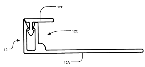
[0044] One aspect of the invention provides a multi-component butt-end trim
structure. FIG. 4 is a cross-sectional view of a multi-component butt-end trim
structure 12 according to a particular embodiment. Trim structure 12 is a type
of
perimeter trim structure which may be used at a butt edge of a wall surface,
at a wall
intersection, at door and window openings, and/or the like. Trim structure 12
of the
illustrated embodiment comprises a butt-end back plate 12A and a butt-end top
cap
CA 02751134 2011-08-30
A
- / -
12B shown best in FIGS. 2B and 3B respectively. When installed on a vertically
extending wall, butt-end trim structure 12 extends vertically along an edge of
a wall
surface and trims the vertical edges of wall panels. Of course, butt-end trim
structure
12 may also be used on walls that are not vertically extending. The
orientation and
angle of butt-end trim structure 12 as installed may vary depending on the
orientation
and angle of the wall surface on which butt-end trim structure 12 is mounted.
[00451 Butt-end trim structure 12 of the FIG. 4 embodiment comprises a butt-
end
back plate 12A shown in FIGS. 2A and 2B and a butt-end top cap 12B shown in
FIGS. 3A and 3B. Butt-end back plate 12A and butt-end top cap 12B may be
fabricated from metal (e.g. aluminum), plastic (e.g., PVC) or other suitable
material.
Butt-end back plate 12A and butt-end top cap 12B may be fabricated by
extrusion and
may therefore have uniform cross sections. In other embodiments, back plate
12A
and top cap 12B may be fabricated using molding (e.g., injection molding)
techniques
or other suitable fabrication techniques. Both butt-end back plate 12A and
butt-end
top cap 12B may be fabricated to have any desired longitudinal lengths (e.g.,
10 feet.
16 feet, 20 feet, or the like). After fabrication, butt-end back plate 12A and
butt-end
top cap 12B may be cut into any desired length for shipping, storage, or
installation.
As explained in more detail below, when top cap 12B is coupled to back plate
12A,
top cap 12B and back plate 12A together define a U-shaped channel 12C for
receiving the edge 14A of a wall panel 14.
[0046) FIGS. 2A and 2B are cross-sectional and isometric views of a butt-end
back plate 12A. Butt-end back plate 12A comprises a base portion 12D and a
connecting portion 12E connected to base portion 12D. Base portion 12D defines
a
generally flat surface for abutting against wall substrate 16. FIGS. 3A and 3B
are
cross-sectional and isometric views of a butt-end top cap 12B. Butt-end top
cap 12B
comprises a cap portion 121 and a connecting portion 12J. Cap portion 121
defines an
outer surface. In FIG. 3A, the outer surface of cap portion 121 is generally
flat,
although this is not mandatory. In other embodiments, the outer surface of cap
portion 121 may be curved. Connecting portion 12J of top cap 12B and
connecting
CA 02751134 2011-08-30
-8-
portion 12E of back plate 12A are adapted to allow top cap 12B and back plate
12A
to be coupled together, by coupling connecting portion 12J of top cap 12B to
connecting portion 12E of back plate 12A. Connecting portion 12E and
connecting
portion 12J may be complementary connecting portions, e.g., connecting portion
12E
and connecting portion 12J comprise complementary coupling features.
[0047] The coupling between coupling portions 12E and 12J may provide a "snap
lock" coupling wherein one or both of connecting portions 12E and 12J is
deformed
during coupling thereof and restorative deformative forces which tend to
restore the
shape of connecting portions 12E, 12J snap the connecting portions 12E, 12J
into a
locked coupling configuration with one another.
[0048] In the FIGS. 2A, 2B, 3A, 3B embodiments, connecting portion 12E
comprises a female connecting portion 12S and connecting portion 12J comprises
a
male connecting portion 12T, and female connecting portion 12S receives a
portion
of male connecting portion 12T in a concavity thereof. In other embodiments,
this
configuration could be reversed.
[0049] In the FIG. 2A embodiment, female connecting portion 12S of back plate
12A comprises bars 12F and 12G extending generally orthogonally from base
portion
12D. In the illustrated embodiment, bar 12F defines a transverse edge of back
plate
12A and bar 12G is spaced apart from bar 12F to define a channel 12H between
bars
12F and 12G. In the FIG. 3A embodiment, butt-end top cap 12B comprises a male
connecting portion 12T. Male connecting portion 12T of top cap 12B and female
connecting portion 12S of back plate 12A are adapted to allow top cap 12B and
back
plate 12A to be coupled together.
[0050] In the FIG. 2A embodiment, bars 12F, 12G of connecting portion 12E
have transverse protrusions 12K, 12L which project into channel 12H and toward
one
another near the distal ends from base portion 12D of bars 12F, 12G. FIG. 2C
is an
CA 02751134 2011-08-30
-9-
enlarged view of an example transverse protrusion 12K. A person skilled in the
art
would recognize that transverse protrusion 12L may have features similar to
transverse protrusion 12K. In FIG. 2C, transverse protrusion 12K has a first
beveled
edge 40 distal from base portion 12D and a second beveled edge 42 proximal to
base
portion 12D. FIG. 2C shows an imaginary line 44 intersecting edge 40 and edge
42.
Imaginary line 44 is parallel to butt-end edge 46 of transverse protrusion
12K. In
FIG. 2C, angle a between edge 42 and line 44 is greater than angle I between
edge 40
and line 44. In some embodiments, angle a is greater than 45 , whereas angle
(3 is
less than 45 . Therefore, it is easier to insert male connecting portion 12T
into female
connecting portion 12S, but more difficult to get male connecting portion 12T
out of
female connecting portion 12S.
100511 In the FIG. 3A embodiment, male connecting portion 12T has a bulbous
head 12M. FIG. 3C is an enlarged view of bulbous head 12M. Bulbous head 12M
has beveled edges 48, 50 which may be complimentary to edges 40, 42 of
transverse
protrusions 12K, 12L. Bulbous head 12M forces bars 12F, 12G apart as inward
force
is applied to top cap 12B. In FIG. 3C, bulbous head 12M has first (distal)
beveled
edge 48 and second (proximal) beveled edge 50. FIG. 3C shows an imaginary line
52
intersecting first edge 48 and edge 50. Imaginary line 52 is parallel to the
distal-
proximal axis 54 of male connecting portion 12T. In FIG. 3C, the angle y
between
edge 48 and line 52 is greater than the angle 8 between edge 50 and line 52.
In some
embodiments, angle y is greater than 45 , whereas angle 6 is less than 45 .
Therefore,
it is easier to insert male connecting portion 12T into female connecting
portion 12S,
but more difficult to get male connecting portion 12T out of female connecting
portion 12S.
[00521 The dimensions and shapes of protrusions 12K, 12L and bulbous head
12M are such that male connecting portion 12T can be forcibly inserted into
and
locked in female connecting portion 12S. When male connecting portion 12T is
forcibly inserted into female connecting portion 12S, male connecting portion
12T
causes bars 12F, 12G to flex slightly outwardly, allowing bulbous head 12M to
pass
CA 02751134 2011-08-30
-10-
beyond transverse protrusions 12K, 12L. Once bulbous head 12M has passed
beyond
transverse protrusions 12K, 12L, the resilience (i.e., restorative deformative
forces) of
bars 12K, 12L causes bars 12K, 12L to flex back inwardly, thereby locking
bulbous
head 12M in female connecting portion 12S. The coupling between top cap 12B
and
back plate 12A may be reversible. Top cap 12B may be decoupled from back plate
12A by exerting a large enough pulling force on top cap 12B to pull male
connecting
portion 12T out of female connecting portion 12S.
[0053] Back plate 12A may comprise a convexity 12N at or near the corner of
base portion 12D and inner bar 12L. In the FIG. 2A embodiment, convexity 12N
has
a generally curved cross section, although this is not necessary. Convexity
12N has a
number of advantages. Convexity 12N adds rigidity and stability at the curved
junction of base portion 12D and inner bar 12L thereby reducing the potential
for
warping and twisting. As will be described in more detail below, convexity 12N
also
lifts wall panel 14 off of base portion 12D thereby supplying a channel for
water
drainage and ventilation. As will be explained further below, convexity 12N
also
functions as a stop for all the horizontal trim components 26 in the rest of
the trim
system, enabling the horizontal trim components 26 to fit with unfinished
edges
hidden behind the top caps 12B while ensuring that the wall panel 14 and top
caps
12B appear to be all on the same plane.
[0054] FIGS. 5A-5C show a method of using multi-component butt-end trim
structure 12. First, back plate 12A is installed on a wall substrate 16.
Substrate 16
may comprise any suitable structural material (e.g., cement, wood frame, steel
frame
and/or the like). In FIGS. 5A-5C, wall substrate 16 is shown as continuous,
although
this is not mandatory. In other embodiments, wall substrate 16 may be
discontinuous.
Back plate 12A may be mounted on substrate 16 by any suitable techniques such
as
nailing, screwing, adhesive and/or the like. Second, a wall panel 14 is
mounted on
top of base portion 12D of back plate 12A. Wall panel 14 may be mounted on
substrate 16 by any suitable techniques such as nailing, screwing, adhesive
and/or the
like. If back plate 12A is provided with convexity 12N, edge 14A of wall panel
14
CA 02751134 2011-08-30
-11-
may rest on convexity 12N, leaving a space 12P between wall panel 14 and base
portion 12D as well as between wall panel 14 and substrate 16 within the wall.
The
space 12P provides a channel for water drainage and ventilation. After
installation of
wall panel 14, top cap 12B is coupled to back plate 12A by forcing connecting
portion 12J of top cap 12B into coupling engagement with connecting portion
12E of
back plate 12A of back plate 12A. Top cap 12B covers edge 14A of wall panel 14
from the outside such that edge 14A of wall panel 14 may not be seen from the
outside of wall. When viewed from the outside, only top cap 12B and wall panel
14
are exposed. Back plate 12A, substrate 16 and edges 14A of wall panel 14 are
hidden
from view.
[00551 In addition to the snap-lock mechanism described above, a bonding agent
may also be applied to connecting portion 12E (e.g., in channel 12H) and or
connecting portion 12J to couple connecting portion 12E to connecting portion
12J.
When a bonding agent is used, connecting portion 12J may be provided with or
without bulbous head 12M and connecting portion 12E may be provided with or
without transverse protrusions 12K, 12L. In some embodiments, the bonding
agent
may be applied to one or both of connecting portions 12E, 12J to minimize the
transmission of moisture through the joint between components 12A, 12B. Such a
bonding agent may be co-extruded. Additionally or alternatively, connecting
portion
12J and connecting portion 12E may also be coupled using other coupling means,
such as friction fit, an adhesive, welding, or a fastener.
100561 Wall panels 14 may be of any suitable shape (e.g., rectangular or
square). Wall panels 14 may be of any suitable thicknesses (e.g., 5/16 inch,
7/16
inch, '/2 inch, 5/8 inch, 1 inch, etc.). Back plate 12A and top cap 12B may be
manufactured to have suitable dimensions to accommodate wall panels 14 of any
particular thickness. Wall panels 14 may be fiber cement panels, wood panels,
composite panels, and/or other types of wall panels. Wall panels 14 may be
provided
with a desired surface finish. For example, wall panels 14 may be provided
with
simulated wood grain, abstracts, masonry surfaces and the like. Similarly,
wood
CA 02751134 2011-08-30
-12-
panels 14 may be provided with a wood veneer, a metal finish, high pressure
laminates, and the like. Examples of wall panels 14 include wall panels
commercially available under the trademark of James Hardie, Certain Teed,
Prodema,
Ceraclad, Swiss Pearl, or Eternit.
[00571 One aspect of the invention provides a multi-component outside corner
perimeter trim structure. FIG. 8A is a cross-sectional view of an example
multi-
component outside corner perimeter trim structure 18. Outside corner perimeter
trim
structure 18 may be used at an outside corner of a wall intersection. When
installed
on a vertically extending wall intersection, outside corner perimeter trim
structure 18
extends vertically along the vertically extending wall intersection. Outside
corner
perimeter trim structure 18 may also be used on wall intersections that are
not
vertically extending.
100581 Outside corner perimeter trim structure 18 comprises a generally L-
shaped
back plate 18A and a generally L-shaped top cap 18B. When back plate 18A and
top
cap 18B are coupled together, they define two generally U-shaped channels 18C,
generally orthogonal (or other substantially non-parallel angle) to each
other, each
channel 18C capable of receiving edge 14A of wall panel 14.
[00591 FIGS. 6A and 6B are cross-sectional and isometric views of an outside
corner back plate 18A. Back plate 18A comprises a generally L-shaped base
portion
18D. In FIG. 6A, base portion 18D comprises two arms in a generally orthogonal
relationship to one another and define a generally L-shaped surface for
abutting
against a wall substrate. In other embodiments, the two arms of base portion
18D are
in a substantially non-parallel angled relationship to one another (e.g.,
greater than 5
and less than 175 ). Back plate 18A also comprises a connecting portion 18E
connected to the outside corner at the intersection of the two arms of the
generally L-
shaped base portion 18D. Connecting portion 18E may have similar features as
connecting portion 12E of butt-end perimeter trim structure 12 described
above. In
the FIG. 6A embodiment, connecting portion 18E is a female connecting portion
that
CA 02751134 2011-08-30
- 13-
comprises bars 18F and 18G extending generally outwardly from the intersection
of
the two arms of the generally L-shaped base portion 18D. Bars 18F and 18G are
spaced apart from each other, defining a channel 18H therebetween.
[0060] FIGS. 7A and 7B are cross-sectional and isometric views of outside
corner
top cap 18B. In FIG. 7A, top cap 18B comprises a generally L-shaped cap
portion
181 and a connecting portion 18J extending from the inside corner at the
intersection
of the two arms of the generally L-shaped cap portion 181. Connecting portion
18J
may have similar features as connecting portion 12J of the butt-end perimeter
trim
structure described above. Connecting portion 18J of top cap 18B can be
inserted and
locked into connecting portion 18E of back plate 18A such that the top cap 18B
and
back plate 18A are coupled together.
[0061] In the FIG. 6A embodiment, bars 18F, 18G of back plate 18A have
transverse protrusions 18K, 18L near the distal end of bars 18F, 18G. In the
FIG. 7A
embodiment, connecting portion18J is a male connecting portion and has a
bulbous
head 18M. The dimensions and shapes of protrusions 18K, 18L and bulbous head
18M are such that connecting portion 18J can be inserted into connecting
portion 18E
and then locked therein. However, top cap 18B may be decoupled from back plate
18A if a worker exerts a force large enough to pull connecting portion 18J out
of
connecting portion 18E.
[0062] Back plate 18A may comprise first convexity 18N at the intersection of
base portion 18D and bar 18F and a second convexity 180 at the intersection of
base
portion 18D and bar 18G. In the FIG. 6A embodiment, convexities 18N, 180 each
has a generally curved cross section, although this is not mandatory. The
functions
and advantages of convexity 18N, 180 are similar to the aforementioned
convexity
12N.
[0063] In use, back plate 18A is first mounted on an outside wall corner. The
two
arms of back plate 18A overlay the two intersecting surfaces of the outside
wall
CA 02751134 2011-08-30
-14-
corner. Second, two wall panels 14 are mounted, one wall panel on top of each
arm
of the back plate 18A. If back plate 18A is provided with convexities 18N,
180, edge
14A of wall panel 14 may rest on convexity 18N, 180, leaving a space 18P
between
wall panel 14 and base portion 18D (see FIG. 8B). The space 18P provides a
channel
for water drainage and ventilation. Third, top cap 18B is coupled to back
plate 18A
by inserting and locking connecting portion 18J into connecting portion 18E.
Top
cap 18B covers the edges of wall panels 14. When viewed from the outside, only
top
cap 18B and wall panels 14 are exposed. Back plate 18A is hidden from view. As
can be seen in FIG. 8B, there is a space 18R between edge 14A of wall panel 14
and
top cap 18B. Space 18R provides an additional channel for water drainage and
ventilation.
[0064] FIGS. 9A, 9B are alternative embodiments of top cap 18P, 18Q. Top cap
18P comprises two L-shaped structures joined together, with male connecting
portion
18J extending from the joint of the two L-shaped structures. Top cap 18Q has a
rounded corner, rather than a square corner. Top caps 18Q, 18P may be coupled
with
back plate 18A in a similar fashion as top cap 18B.
[0065] One aspect of the invention provides a multi-component inside corner
perimeter trim structure. FIG. 12A is a cross-sectional view of an example
multi-
component inside corner perimeter trim structure 20. Inside corner perimeter
trim
structure 20 may be used at an inside corner of a wall intersection. When
installed on
a vertically extending wall intersection, inside corner perimeter trim
structure 20
extends vertically along the vertically extending wall intersection. Inside
corner
perimeter trim structure 20 may also be used on wall intersections that are
not
vertically extending.
[0066] Inside corner perimeter trim structure 20 comprises a generally L-
shaped
back plate 20A and a generally L-shaped top cap 20B. When back plate 20A and
top
cap 20B are coupled together, they define two generally U-shaped channels 20C,
generally orthogonal to one another, each channel 20C capable of receiving the
edge
CA 02751134 2011-08-30
-15-
14A of a wall panel 14.
[0067] FIGS. 1 OA and I OB are cross-sectional and isometric views of an
inside
corner back plate 20A. Back plate 20A comprises a generally L-shaped base
portion
20D and a connecting portion 20E connected to the inside corner at the
intersection of
the two arms of the generally L-shaped base portion 20D. Connecting portion
20E
may have similar features as connecting portion 12E of the butt-end perimeter
trim
structure described above. In the FIG. 1 OA embodiment, connecting portion 20E
is a
female connecting portion and comprises bars 20F and 20G extending from an
inside
corner at the intersection of the two arms of the generally L-shaped base
portion 20D.
Bars 20F and 20G are spaced apart from each other, defining a channel 20H
therebetween.
[0068] FIGS. 11 A and 11 B are cross-sectional and isometric views of inside
corner top cap 20B. Top cap 20B comprises a generally L-shaped cap portion 201
and a connecting portion 20J extending outwardly from the corner at the
intersection
of the two arms of the generally L-shaped cap portion 201. Connecting portion
20J
may have similar features as connecting portion 12J of the butt-end perimeter
trim
structure described above. Connecting portion 20J of top cap 20B can be
inserted and
locked into the connecting portion 20E of back plate 20A such that the top cap
20B
and back plate 20A are coupled together.
[0069] In the FIG. 1 OA embodiment, bars 20F, 20G of back plate 20A have
transverse protrusions 20K, 20L near the distal end of bars 20F, 20G. In the
FIG.
11A embodiment, connecting portion 20J is a male connecting portion and has a
bulbous head 20M. The dimensions and shapes of protrusions 20K, 20L and
bulbous
head 20M are such that male connecting portion 20J can be inserted into female
connecting portion 20E and then locked therein. However, top cap 20B may be
decoupled from back plate 20A if a worker exerts a force large enough to pull
connecting portion 20J out of connecting portion 20E.
CA 02751134 2011-08-30
-16-
[00701 Back plate 20A may comprise a first convexity 20N near the intersection
of base portion 20D and bar 20F and a second convexity 200 at the intersection
of
base portion 20D and bar 20G. In the FIG. I OA embodiment, convexities 20N,
200
each has a generally curved cross section, although this is not mandatory. The
functions and advantages of convexities 20N, 200 are similar to the
aforementioned
convexity 12N.
[00711 In use, back plate 20A is first mounted on an inside wall corner. The
two
arms of back plate 20A overlay the two intersecting surfaces of the inside
wall corner.
Second, two wall panels 14 are mounted, one wall panel on top of each arm of
the
back plate 20A. If back plate 20A is provided with convexities 20N, 200, an
edge
14A of wall panel 14 may rest on convexity 20N, 200, leaving a space 20P
between
wall panel 14 and base portion 20D (see FIG. 12B). The space 20P provides a
channel for water drainage and ventilation. Third, top cap 20B is coupled to
back
plate 20A by inserting and locking connecting portion 20J into connecting
portion
20E. Top cap 20B covers the edges of wall panels 14. When viewed from the
outside, only top cap 20B and wall panels 14 are exposed. Back plate 20A is
hidden
from view. As can be seen in FIG. 12B, there is a space 20R between edge 14A
of
wall panel 14 and top cap 20B. Space 20R provides an additional channel for
water
drainage and ventilation.
[00721 One aspect of the invention provides a multi-component internal
vertical
trim structure. FIG. 16C is a cross-sectional view of an example multi-
component
internal vertical trim structure 24. Internal vertical trim structure 22 may
be used to
trim the edges of two adjacent wall panels at an internal location on a wall
(i.e., not at
a perimeter or terminal edge of a wall). When installed on a vertically
extending
wall, internal trim structure 24 extends vertically.
[00731 Internal trim structure 24 comprises a back plate 24A and a top cap
24B.
When back plate 24A and top cap 24B are coupled together, they define two
generally U-shaped channels 24C, generally parallel and facing away from each
CA 02751134 2011-08-30
-17-
other, and each channel 24C capable of receiving the edge 14A of a wall panel
14.
[0074] FIG. 16B is a cross-sectional view of back plate 24A. Back plate 22A
comprises a base portion 24D and a connecting portion 24E extending from a
middle
region of base portion 24D. In the FIG. 16B embodiment, connecting portion 24E
is
a female connecting portion comprises bars 24F and 24G extending orthogonally
from base portion 24D. Bars 24F and 24G are spaced apart from each other,
defining
a channel 24H therebetween.
[0075] FIG. 16A is a cross-sectional view of top cap 24B. Top cap 24B
comprises a cap portion 241 and a connecting portion 24J that extends from the
cap
portions 241. In the FIG. 16A embodiment, connecting portion 24J of top cap
24B is
a male connecting portion and can be inserted and locked into connecting
portion 24E
of back plate 24A such that the top cap 24B and back plate 24A are coupled
together.
[0076] In the FIG. 16B embodiment, bars 24F, 24G of back plate 24A have
transverse protrusions 24K, 24L near the tip of bars 24F, 24G. In the FIG. 16A
embodiment, connecting portion 24J has transverse protrusions 24M. Connecting
portion 24J can be inserted into connecting portion 24E and then locked
therein.
However, top cap 24B may be decoupled from back plate 24A if a worker exerts a
force large enough to pull connecting portion 24J out of connecting portion
24E.
[0077] Back plate 24A may comprise a first convexity 24N near the intersection
of base portion 24D and bar 24F and a second convexity 240 at the intersection
of
base portion 24D and bar 24G. In the FIG. 16B embodiment, convexities 24N, 240
each has a curved cross section. The functions and advantages of convexity
24N,
240 are similar to the aforementioned convexity 12N.
[0078] In use, back plate 24A is first mounted on wall substrate 16. Second,
two
wall panels are mounted, one on each side of the back plate 24A. Third, top
cap 24B
is coupled to back plate 24A by inserting and locking male connecting portion
24J
CA 02751134 2011-08-30
-18-
into female connecting portion 24E. Top cap 24B covers the edges of wall
panels.
When viewed from the outside, only top cap 24B and wall panels 14 are exposed.
Back plate 24A is hidden from view.
[0079] FIGS. 15A-15C show an alternative embodiment of a multi-component
internal vertical trim structure 22. The structure and function of internal
vertical trim
structure 22 is similar to internal vertical trim structure 24, but the
connecting
portions 22E, 22J of structure 22 have larger dimensions than structure 22.
Similar
structures in FIGS. 15A-15C are labeled using similar reference numerals as in
FIGS.
16A-I6C, except that "24" is replaced with "22".
[0080] The trim system according to the present invention may also include
horizontally extending trim components such as horizontal trim components 26
and
soffit J pieces 28.
[00811 Horizontal trim component 26 may be used to trim a top or bottom
horizontal edge of a wall panel 14. FIGS. 13A and 13B are cross-sectional and
isometric views of a horizontal trim component 26. Horizontal trim component
26
comprises a flange portion 26A, a ledge portion 26B and a tab portion 26C.
Flange
portion 26A is generally parallel to tab portion 26C. The angle between flange
portion 26A and ledge portion 26B may be in the range of 90 to 120 . In a
particular
embodiment, the angle is 96.6 . When the angle is greater than 90 , ledge
portion
26B slopes downwardly. The slope of ledge portion 26B allows water to drain
away
from the wall.
[0082] Horizontal trim component 26 may be used on internal location on a wall
surface, or above windows or doors, or at the base of a wall. For finishing or
capping
the top of a wall, soffit J piece 28 may also be used. FIGS. 14A and 14B are
cross-
sectional and isometric views of an example soffit J piece 28.
CA 02751134 2011-08-30
-19-
[00831 FIGS. 17 and 18 are exploded and assembled isometric views of a
horizontal trim component 26 and two vertical trim structures (a butt-end trim
structure 12 and an internal vertical trim structure 22). To better show the
interaction
between horizontal trim component 26 and butt-end trim structure 12 and
internal
vertical trim structure 22, top caps 12B, 22B and wall panels 14 are not shown
in
FIGS. 17 and 18. Horizontal trim component 26 extends from butt-end trim
structure
12 to internal vertical trim structure 22. The ends of horizontal trim
component 26
stop at convexities 12N and 22N. Flange portion 26A of horizontal trim
component
26 overlies base portion 12D of butt-end trim structure 12 and base portion
22D of
internal vertical trim structure 22. In some embodiments, because of the
overlying
feature, a single fastener (not shown) may pass through both flange portion
26A and
base portion 12D or both flange portion 26A and base portion 22D to secure
horizontal trim component 26, butt-end trim structure 12, and internal
vertical trim
structure 22 to wall substrate 16 (not shown).
[00841 FIG. 19 is a front plan view of a vertically extending wall section
comprising an array of 3x3 wall panels 14. The array of wall panels is trimmed
by
two butt-end trim structures 12 at the vertical perimeter edges of the wall
section, and
two internal trim structure 24. It should be recognized that internal trim
structures 22
may be used instead of internal trim structure 24. In the FIG. 19 embodiment,
only
top caps 12A, 24A of butt-end trim structure 12 and internal trim structure 24
are
visible to the viewer. Butt-end trim structures 12 and internal trim
structures 24
extend from top to bottom of the wall section. The horizontal edges of wall
panels 14
are trimmed by a plurality of horizontally extending horizontal trim
components 26
which are placed between the vertically extending butt-end trim structures 12
and
internal trim structures 24 to form a grid-like pattern. It should be noted
that in the
FIG. 19 embodiment horizontal trim components 26 are not continuous along the
horizontal dimension of the wall section.
100851 The installation of a wall section comprising an array of wall panels
may
be carried out as follows. First, back plates 12A of butt-end trim structures
12 and
CA 02751134 2011-08-30
-20-
back plate 22A or 24A of internal trim structures 22 or 24 are mounted on wall
substrate 16. Second, a plurality of horizontal trim components 26 is mounted
on
wall substrate 16 generally orthogonal to back plates 12A and 22A or 24A in
appropriately spaced-apart rows to form a grid. Third, an array of wall panels
14 is
mounted on wall substrate 16 in spaces defined by the grid. The upper edge of
wall
panel 14 is received under tab portion 26C of horizontal trim component 26
above.
The bottom edge of wall panels 14 lies above ledge portions 26B of horizontal
trim
component 26 below. The two lateral edges of wall panel 14 may sit upon
convexities of butt-end trim structures 12 and internal vertical trim
structure 22 (or
24). Fourth, top caps 12B and 22B (or 24B) are placed on top of back plates
12A and
22A (or 24A) and locked together. Top caps 12B and 22B (or 24B) cover the two
lateral edges of wall panel 14.
[00861 Although it is possible to assemble a butt-end trim structure 12 from a
single back plate 12A and a single top cap 12B, it is also possible to
assemble a butt-
end trim structure 12 from two or more back plate 12A and two or more top cap
12B.
Two or more back plate 12A can join together in an end-to-end relationship to
form a
back plate assembly. Similarly, two or more top caps 12B can join together in
an
end-to-end relationship to form a top cap assembly. In an assembly, top caps
12B,
may be coterminous with back plates 12A. Alternatively, top caps 12B and back
plates 12A may be in an offset or staggered fashion, i.e., the uppermost
longitudinal
end of top cap 12B is offset from the uppermost longitudinal end of back plate
12A
and/or the lowermost longitudinal end of top cap 12B is offset from the
lowermost
longitudinal end of back plate 12A. Such coterminous and/or offset assemblies
can
also be assembled from multi-component outside corner perimeter trim
structures 18
and multi-component inside corner perimeter trim structures 20.
[00871 FIGS. 20 and 21 are exploded and assembled isometric views of two butt-
end trim structure back plates 12A and one butt-end trim structure top cap 12B
in an
offset assembly. FIGS. 22 and 23 are exploded and assembled isometric views of
two
outside corner back plates 18A and one outside corner top cap 18B in an offset
CA 02751134 2011-08-30
-21 -
assembly. The offset feature is made possible because each trim structure
comprises
two pieces, i.e., a back plate and a top cap. The offset feature provides a
number of
advantages. It strengthens the integrity of the assembly and makes the
assembly
more resistant to bending, warping or twisting. The top caps may visually
conceal
any bending or twisting commonly taking place at the junction of two abutting
back
plates. It allows back plates and top caps of different lengths to be
assembled
together, permitting more versatility. It also allows back plates and top caps
to be cut
into shorter lengths for ease of transportation and storage and then be
assembled at
the work site. These advantages would not be achieved if the trim structure is
of a
single-piece construction.
[0088] The multi-component perimeter trim structure (multi-component butt-end
trim structure 12, outside corner perimeter trim structure 18, and inside
corner
perimeter trim structure 20) according to the present invention provides a
number of
additional advantages over prior art one-piece perimeter trim components. It
allows a
wall panel to be easily installed without the risk of the wall panels being
damaged,
broken or deformed as with prior art one-piece perimeter trim components. It
allows
a worker to inspect the edge of a wall panel during installation to ensure
that the edge
has been sealed as per manufacturer's instructions or is not damaged or broken
or
deformed before installing the top cap to cover the edge. With the prior art
one-piece
perimeter trim component, a worker cannot inspect the edge of the wall panel
when it
is forcibly inserted into the channel in the one-piece perimeter trim piece.
The multi-
component perimeter structure also allows a worker to remove the top cap to
allow
removal and replacement of a wall panel that has already been installed or
damaged.
With the prior art one-piece perimeter trim component, there is no easy way to
remove a wall panel that has already been installed, as the edge of the wall
panel is
inserted in the U-shaped channel of the one-piece perimeter trim component on
both
sides of the wall panel .
[0089] The multi-component perimeter trim structure (multi-component butt-end
trim structure 12, outside corner perimeter trim structure 18, and inside
corner
CA 02751134 2011-08-30
-22-
perimeter trim structure 20) according to the present invention is also
advantageous
over the aluminum reveals wall systems commercially available under the
trademark
EasyTrim. The EasyTrim system does not use multi-component perimeter trim
structures, although it uses multi-component internal trim structures. As a
result, in
many instances where a wall panel must be installed between two vertical
perimeter
pieces, the installer experiences the same frustrations as described in the
prior art.
The EasyTrim system also requires horizontal trim components to extend the
entire
horizontal length of a wall section, and the internal trim structures are not
continuous
from top to bottom of a wall section. As a result, not only is bending,
warping and
twisting of trim visible at all their vertical perimeter pieces, but also all
horizontal
joints between the top caps. In contrast, the trim system comprising the multi-
component perimeter trim structure according to the present invention allows
the
internal trim structures to run continuously from top to bottom of a wall
section. This
increases the strength and integrity of the internal trim structure and hides
both
horizontal and vertical bending.
100901 As will be apparent to those skilled in the art in the light of the
foregoing
disclosure, many alterations and modifications are possible in the practice of
this
invention without departing from the spirit or scope thereof. For example: the
configuration of male and female connecting portions in perimeter trim
structures
may be reversed. FIGS. 24-26 shows alternative embodiments of butt-end trim
structure 12, outside corner perimeter trim structure 18 and inside corner
perimeter
trim structure 20 respectively wherein the female connecting portion is
located on the
top cap and the male connecting portion is located on the back plate.