Note: Descriptions are shown in the official language in which they were submitted.
CA 02751406 2011-08-03
WO 2010/091659 PCT/DE2010/000104
1
Method for Producing a Blade Plating
on a Blade for a Turbomachine
The invention relates to a method for producing a blade tip plating on a blade
for a turbo
machine, particularly on a high-pressure running compressor blade for a gas
turbine.
A method of this type is known from DE 10 2005 030 848 Al, with which method
blade tip
platings made of hard material particles can be applied particularly also [sic
-- Translator]
blades made of a nickel-based material or of a nickel-based alloy. In this
method, first a nickel-
based solder is applied to a blade made of a nickel-based material, in the
region of the blade tip.
Hard material particles comprising cubic boron nitride (CBN), coated with an
active element,
are then applied to the solder. When the solder is subsequently melted under a
vacuum or
protective gas to form a matrix that encompasses the hard material particles,
a stable
connection is produced between the hard material particles and the blade tip.
DE 44 39 950 C2 shows a method for producing a blade tip plating on a blade
made of a
titanium-based alloy. A solder is applied in layers to the blade. Hard
material particles are
then applied to the blade that is coated with the solder. The components of
the solder are then
melted, in order to encase the hard material particles within a matrix.
In the method known from DE 44 39 950 C2, to affix the hard material particles
on the layers
on the blade side, an outer layer of adhesive (thermoplastic plastic) is
applied, wherein the
actual adhesion can take place during or after covering. In contrast,
individual hard material
particles that are covered with a metal coating or a metallic pre-coating are
affixed onto the
surface of the blade is carried out via resistance welding. However, the hard
material particles
can also be mixed with a paste consisting of fluxing agent and the elemental
components of the
solder in powdered form, and then applied to the surfaces, before melting is
carried out.
In principle, the need exists for an automation of the application of the hard
material particles,
since manually covering a film solder with individual hard material particles
is a time-consuming
CA 02751406 2011-08-03
WO 2010/091659 PCT/DE2010/000104
2
and therefore costly process. However, more cost-effective methods, such as
the galvanic
application of hard material particles in a metallic matrix, result in a
complete covering of the
blade tip with hard material particles; the hard material particles cannot be
selectively
positioned at a feasible cost. A complete covering is undesirable, as it
results in a substantial
negative impairment of the fatigue strength of the blade.
The problem addressed by the invention is that of simplifying the production
of an optimal
blade tip plating with hard material particles.
This problem is solved by a method for producing a blade tip plating on a
blade for a turbo
machine, having the features of claim 1. Advantageous and expedient
embodiments of the
method according to the invention are specified in the dependent claims.
The method according to the invention in its most general form comprises the
following steps:
- Producing a particle composite material having embedded hard material
particles;
- Placing the particle composite material on a solder applied to the blade
tip; and
- Heating the solder.
A particle composite material within the context of the invention is
understood as a unit
consisting of a holding material and particles embedded therein.
Using a particle composite material having embedded hard material particles in
the production
of a blade tip plating has the advantage that the hard material particles need
not be manually
placed individually on the solder. Applying the hard material particles over a
holding material
saves fabrication time, while at the same time enabling a selective
positioning of the hard
material particles, since the particle composite material can be molded either
during the
production thereof or subsequently as desired. This enables a rapid, selective
arrangement of
the hard material particles along the so-called skeleton line of the blade tip
- which is highly
CA 02751406 2011-08-03
WO 2010/091659 PCT/DE2010/000104
3
time-consuming and thus expensive when performed manually - the best
functioning blade tip
plating in the compressor region is achieved [sic Translator].
As the holding material for the hard material particles, a preferably
thermoplastic plastic is
suitable, i.e., the particle composite material contains a preferably
thermoplastic plastic in
which the hard material particles are embedded. When heated, the plastic can
be cast or
injected into a suitable mold. If applicable, subsequent molding or bending
can also be
supported by heating.
According to a preferred first embodiment of the invention, a molded article
formed from the
particle composite material is placed on the solder. The production of a
molded article has the
advantage, for example, that the particle composite material to be placed is
already in its
finished shape, and further processing (cutting to shape, bending) is not
necessary.
Preferably, the molded article is produced as elongated and having a curvature
which conforms
to the shape of the skeleton line of the blade tip.
To produce a molded article of this type, the hard material particles and a
preferably
thermoplastic plastic material can be introduced into a special mold (e.g., by
injection
molding), which conforms to the skeleton line of the blade tip.
According to a second embodiment of the invention, a wire-like, pre-shaped
formed body from
the particle composite material is placed on the solder. This embodiment has
the advantage, for
instance, that in a preceding process step, a greater quantity of particle
composite material that
is suitable for placement can be produced in advance. The wire-like formed
body can be
subsequently adapted to conform to different blade tip designs.
To produce the wire-like formed body, hard material particles can be
introduced into a
preferably thermoplastic plastic material, and an injection molding tool can
be used.
CA 02751406 2011-08-03
WO 2010/091659 PCT/DE2010/000104
4
Using a tool, the wire-like formed body can be easily bent according to the
above-described
understanding such that the curvature conforms to the shape of the skeleton
line of the blade
tip.
The method according to the second embodiment of the invention can be further
optimized in
that the wire-like formed body is placed on the blade tip automatically with
the help of an
optical or touch control system.
Additional features and advantages are found in the following description and
in the attached
set of drawings, to which reference will be made. The drawings show:
- Figure 1 a high-pressure running compressor blade for a gas turbine having a
blade tip plating;
- Figure 2 a mold, filled with hard material particles, to be used for
producing a
molded article made of particle composite material according to a first
embodiment of
the method according to the invention;
- Figure 3 a section of a blade tip with solder film and molded article
applied;
- Figure 4 the section of the blade tip of Figure 3 having hard material
particles
recessed into the solder film;
- Figure 5 a container with adhesive material and hard material particles for
producing a molded article made of particle composite material according to a
second
embodiment of the method according to the invention; and
- Figure 6 an injection molding device for producing the molded article made
of
particle composite material according to the second embodiment.
CA 02751406 2011-08-03
WO 2010/091659 PCT/DE2010/000104
Figure 1 shows a simplified illustration of a running blade 10 for a high-
pressure compressor of
a gas turbine aircraft engine. The running blade 10 comprises a blade 12 and -
referred to the
installed state thereof - a blade root 14 positioned radially toward the
inside and a blade tip 16
positioned radially toward the outside. To protect the blade tip from wear
from stripping in a
stationary housing, the blade tip 16 has a plating 20 containing hard material
particles 18,
which is produced by the method according to the invention. Cubic boron
nitride (CBN) is a
particularly suitable material for the hard material particles for the plating
20.
In what follows, the production of the blade tip plating 20 according to a
first embodiment of
the method according to the invention will be described.
Figure 2 shows a mold 22 for producing a molded article 24 made of particle
composite
material. The mold 22 is shape to conform to the blade tip. In particular, the
length of the
mold 22 corresponds to the length L of the blade tip 16, and the longitudinal
curvature of the
mold 22 conforms to the shape of the skeleton line 26 of the blade tip 16.
Within this context,
the skeleton line is understood as the line that connects the centers of
circles that can be
inscribed within the profile of the blade tip 16 (from a plan view), i.e., the
profile shape of the
blade tip 16 is symmetrical about its skeleton line 26.
Hard material particles 18, for example, made of CBN, are introduced into the
mold 22 in such
a way that the hard material particles 18 lie as close to one another as
possible. A preferably
thermoplastic plastic material 28, which serves as adhesive, is then filled
into the mold 22,
pressureless or under pressure (on the basis of the property of the material),
until said material
at least partially encompasses the hard material particles 18. When the
plastic material 28
solidifies (hardens), a particle composite material forms, which can be
removed from the mold
22 as a molded article 24. To promote this, the mold 22 can be coated with an
anti-stick
substance and/or can be separable. Because the length of the molded article 24
is significantly
greater than its width, it has a wire-like form.
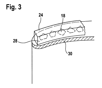
The molded article 24 is then fastened to a solder film 30, which has been cut
to shape in
advance and placed on the blade tip, along the skeleton line 26 of the blade
tip 16, as shown in
Fig. 3. Inductively heating the solder film 30 causes it to melt, and the hard
material particles
CA 02751406 2011-08-03
WO 2010/091659 PCT/DE2010/000104
6
18 sink into the molten material of the solder film 30, as shown in Figure 4.
In addition, the
plastic material 28 vaporizes and/or burns essentially without residue.
The plating 20 produced in this manner is securely fastened to the blade tip
16, wherein the
hard material particles 18 are arranged as desired along the skeleton line 26
of the blade tip 16.
A second embodiment of the method according to the invention provides an
alternative
production of the molded article 24. The hard material particles 18 are
introduced, for
example,
in a vessel 32, into a preferably thermoplastic plastic material 28 that
serves as adhesive, in
such a way that they lie as close to one another as possible, as shown in Fig.
5.
Using an optionally adapted injection molding tool 34, an elongated,
preferably wire-like,
formed body 36 is molded from the plastic/hard material particle mixture, as
shown in Fig. 6.
This wire-like formed body 36 is cut to a length that corresponds to the
distance between the
leading and trailing edges of the blade tip 16.
The wire-like formed body 36 is then shaped in a suitable tool to conform to
the shape of the
skeleton line 26 of the blade tip 16. The properties of the molded article 24
made of particle
composite material and formed in this manner correspond to those of the molded
article 24
produced according to the first embodiment. The molded article 24 is
accordingly fastened to
the blade tip 16 along the skeleton line 26 thereof as was described for the
first embodiment,
using a solder film 30 and inductive heating thereof
A length of the wire-like formed body 36 can also be produced in quantity in
advance and held
in storage wound onto a reel, for example. The wire-like formed body 36 can be
applied to a
blade tip 16 automatically, in that the wire-like formed body 36 is unwound
from the reel, and
adaptively placed on the blade tip 16, along the skeleton line 26 thereof, by
means of a touch or
optical control system. Placement can advantageously be combined with the
heating of the
solder (soldering) to form a single process step.
CA 02751406 2011-08-03
WO 2010/091659 PCT/DE2010/000104
7
According to a further developed aspect of the invention, with a suitable
geometry of the blade
tip 16, particularly with a largely uniform width over the entire chord length
of the blade tip
profile, the solder film 30 that has been cut to size can also be replaced by
a solder wire. The
solder wire can be unwound from a reel and placed on the blade tip 16 using
suitable devices
(as described above for the wire-like formed body 36 made of particle
composite material) and
fastened to the blade tip 16 by means of spot gluing. In a subsequent step,
the formed body 36
made of particle composite material is then placed on the solder wire, before
or as the solder
wire is heated.