Note: Descriptions are shown in the official language in which they were submitted.
CA 02751650 2011-08-17
-1..
TWIN ELEVATOR SYSTEMS
Rory S. Smith
Randolph W. Huff
Richard D, Peters
Bruce Powell
Gerhard Thunun
Field of the Invention
[00011 The present invention relates to systems and methods of deploying
elevator systems, in particular, the deployment of a plurality of
deployment schemes associated with twin elevator systems.
Backaround of the Invention
t00021 In multi-storey buildings, one of the main objectives is to
efficiently
transport passengers to various floors using an elevator system. In
designing, developing, and deploying elevator systems, particular
attention should be paid to the portion of the building core that is
dedicated to the elevator system. For example, as the number of
elevator shafts are increased to meet the demands of higher buildings,
maximizing real estate space as a commodity is also a main concern
that must be addressed. Therefore, the object is to try and minimize the
required number of elevator shafts that are deployed within an elevator
system, while also trying to effectively meet the transportation needs
of passengers and freight within the building. For example, a poorly
=
designed elevator system may cause unacceptable delays for
passengers trying to reach a desired floor. However, solutions to try
and reduce the number of shafts and improve service have included
higher elevator travel speeds, shorter door opening/clOsing times,
advanced control systems, express elevators, splitting buildings into
= zones, etc. These solutions, while relatively successful in addressing
some of the challenges, may not be acceptable by the user. These
CA 02751650 2011-08-17
- 2 -
reasons may include a feeling of unease when elevators accelerate,
doors quickly closing, or difficulties that may be experienced as the
result of using a complicated system, where passengers may have to
change one or several times to get to a desired floor.
[0003] Despite the mentioned optimization measures, it is evident that the
largest part or portion of the elevator shaft is not used when the
elevator car is in another part of the shaft. One solution attempting to
capitalize on this is the double-decker elevator. However, some of the
disadvantages of such a system are the large scale drives and power
supplies that become necessary for accelerating such a large mass.
Also, as the cars are semi-connected, the delays for passengers waiting
for other passengers to exit and enter the elevator may be more as a
result of two floors being simultaneously served. Moreover, the stories
of the building would have to be virtually equidistant, which is an
expensive objective to meet in a building.
[0004) It is therefore an object of the present invention to provide an
elevator
system that is capable of effectively maximizing an elevator shaft by
accommodating more than one independently controllable elevator car
within a shaft.
[0005] It is another object of the present invention to deploy various
elevator
schemes using more than one elevator car within each elevator shaft
based on different buildings, where each building co. mprises a different
number of floors and elevator shafts.
Brief Summary of the Invention
00i:06] The present invention provides elevator system architectures and
methods that employ the use of two elevator cars within a single
elevator shaft, where each of the two elevator cars move independently
of each other within the shaft.
CA 02751650 2011-08-17
-3-
100071 An aspect of the present invention according to the present
invention
provides an elevator system having at least two independently operable
elevator cars in each of a plurality of elevator shafts within a building.
The system comprises at least one first elevator shaft having a lower
first and a lower second region, where a first elevator car moves within
the lower first region and a second elevator car moves within the lower
second region. Both the first and second elevators are moveably
controlled independently of each other, where each elevator car moves
independently of the other in the first elevator shaft. The elevator
systena also comprises at least one second elevator shaft having an
upper first and an upper second region, where a third elevator car
moves within the upper first region and a fourth elevator car moves
within the upper second region. The third and fourth elevator are also
moveably controlled independently of each other, where each elevator
car moves independently of the other in the second elevator shaft.
[00081 Another aspect of the present invention according to the present
invention provides an elevator system within a building that comprises
at least one first elevator shaft that includes a lower first and a lower
second region. A first elevator car moves within the lower first region
and a second elevator car moves within the lower second region,
wherein the first and second elevator are moveably controlled
independently of each other. At least one second elevator shaft has a
lower sky lobby and an upper sky lobby separated from the lower sky
lobby by a plurality of mid-level floors, whereby a third elevator car
moves between a ground floor of the building and the lower sky lobby,
and a fourth elevator car moves between the ground floor and the
upper sky lobby. The third and fourth elevator are also moveably
controlled independently of each other,
00091 Yet another aspect of the present invention provides an elevator
system
having two elevator cars within each elevator shaft for providing goods
CA 02751650 2011-08-17
- 4 -
and passenger transportation to a plurality of floors of a building. The
elevator system comprises at least one elevator shaft comprising a
virtual landing region located above a top floor of the plurality of
floors of the building. A goods elevator car moves within the at least
one elevator shaft between a basement floor and the top floor
associated with the plurality of floors. A passenger elevator car moves
within the at least one elevator shaft between a ground floor associated
with the plurality of floors and the virtual landing, wherein the
passenger elevator car moves into the virtual landing for allowing
accessibility of the goods elevator car to the top floor. The goods
elevator car and passenger elevator car are moveably controlled
independently of each other within the at least one elevator shaft,
whereby each elevator car moves independently of the other in the at
least one elevator shaft.
[00101 According to another aspect of the present invention, an elevator
system comprises two elevator cars within each elevator shaft for
passenger transportation to a plurality of floors of a building. The
elevator system further comprises at least one elevator shaft
comprising a first region and a second region, where the first region
eXtends from a ground level to a plurality of sub-ground levels. The
second region extends from the ground level to a top floor of the
building, where a first and a second elevator car move within the at
least one elevator shaft. The first elevator car moves within the first
region and the second elevator car moves within the second region,
wherein the first and the second elevator cars are moveably controlled
independently of each other within the at least one elevator shaft.
[0011] According to yet another aspect of the present invention, a method
of
operating an elevator system comprises a first and a second
independently operable elevator car within each elevator shaft within a
building. The method comprises the steps of assigning the first elevator
CA 02751650 2011-08-17
- 5 -
to operate within a first region of the elevator shaft, and assigning the
second elevator to operate within a second regjon of the elevator shaft,
where the second region is located above the first region. The first and
the second elevator car are loaded from a ground floor level, where the
loading of the second elevator car from the ground floor is controlled
by moving the first elevator below the level of the ground floor to a
lower level zone.
[00121 In accordance with another aspect of the present invention, a method
is
provided for operating an elevator system comprising a first and a
second independently operable elevator car within. each at least one
elevator shaft of a building. The method comprises the steps of
providing passenger transportation between a ground floor level and a
top floor of the building using the first elevator car within the at least
one elevator shaft. Also provided is passenger transportation between a
sub-ground floor level and a top floor of the building using the second
elevator car within the at least one elevator shaft. The loading of the
first elevator car from the top floor is controlled by moving the second
elevator above the level of the top floor to a virtual landing region.
Biter Description of the Draxdosts
10013) Figure 1 illustrates an elevator system deployment scheme employing
two independently moving elevator cars operating within each elevator
shaft according to an aspect of the present invention, where the lower
floors are serviced by a first group of elevator cars, and the upper
floors are serviced by a second group via an express zone.
[0014] Figure 2 illustrates an elevator system deployment scheme employing
two independently moving elevator cars operating within each elevator
shaft according to an aspect of the present invention, where the upper
floors are serviced by two shuttle cars operating within the same
=elevator shaft.
CA 02751650 2011-08-17
- 6 -
[00151 Figure 3 illustrates an elevator system deployment scheme employing
two independently moving elevator cars operating within each elevator
shaft according to an aspect of the present invention, where an elevator
motion-free zone is established within each shaft.
[00161 Figure 4 illustrates an elevator system deployment scheme employing
two independently moving elevator cars operating within each elevator
shaft according to an aspect of the present invention, where the upper
floors are serviced by double deck shuttles for transporting passengers
to lobbies that provide access to the upper floors that utilize the two
independently moving elevator cars operating within each elevator
shaft.
[00171 Figure 5 illustrates an elevator system deployment scheme employing
two independently moving elevator cars operating within each elevator
shaft according to an aspect of the present invention, where an upper
floor virtual landing is provided.
[00181 Figure 6 illustrates an elevator system deployment scheme employing
two independently moving elevator cars operating within each elevator
shaft according to an aspect of the present invention, where a lower
ground level virtual landing is provided.
[0019] Figure 7 illustrates an elevator system deployment scheme employing
two independently moving elevator cars operating within each elevator
shaft according to an aspect of the present invention, where one of the
= two independently moving elevator cars services sub-ground level =
floors, and the other elevator car accordingly services the floors above
ground level.
Detailed_Descriotion of the Inveatiou
[00201 Figure 1 illustrates an elevator system deployment scheme 100
employing two independently moving elevator cars (Twin Cars)
CA 02751650 2011-08-17
- 7 -
operating within each elevator shaft according to an aspect of the
present invention, The system 100 according to the present invention
represents a zoned twin elevator system. Each elevator car or lift
operates within an elevator shaft, where each shaft is designated by a
lift number 102 (e.g., 1-12), Elevator shafts 1-12, as indicated by 104,
are illustrated at the bottom of deployment scheme 100, where a first
group of elevator shafts, indicated by 106, provide transportation
= services to a first region of floors within a building (e.g., floors 1-
2.0),
=
as indicated by 108. A second group of elevator shafts, indicated by
110, similarly provide transportation services to a second region of
floors with the building (e.g., floors 21-40), as indicated by 112.
[00211 Within the first
group of elevator shafts, indicated by 106, elevator
shaft 114 comprises a twin elevator system incorporating two elevator
cars that move independently of each other, where independent motion
is enabled by providing separate counter weight, rope, and traction
drive units for each elevator car. A first region 116 within shaft 114,
denoted by lighter colored circles, indicate the floors (i.e., floors 1-10)
that are serviced by a first elevator car (not shown) associated with the
twin elevator cars. A second region 118 within shaft 114, denoted by
the dark colored circles, indicate floors (i.e., floors 11-20) that are
serviced by a second elevator car (not shown). Passengers or uses
requiring transportation to floors in the first region 116 may enter the
first elevator car on a lower ground level 120 of the building, whereas
passengers or users traveling to the floors associated with the second
region 118 may enter the second elevator car from the upper ground
level 122. Access between the upper and lower ground levels may be
provided, for example, by a connecting stair case, a shuttle elevator,
and/or an escalator 124. All the other elevator shafts 126,128, 130,
132,134 within the first group of elevators 106 are identical to that of
elevator shaft 114, described above.
CA 02751650 2011-08-17
- 8 -
[00221 The number of
elevator shafts designated for each elevator group, and
the number of floors associated with each region (e.g., floors 1-10 in
the first region 1.16) are for purposes of illustration and not limitation,
and may vary according to various elevator system design factors (e.g.,
building size, traffic, etc.). Also, it may be possible to increase the
number of elevator cars operating within each shaft to more than two.
[00231 One or more elevator
system controllers (not shown) naay include
various safety and monitoring procedures for ensuring that the
independently moving elevator oars sharing a shaft do not come within
a certain range or distance of each other for collision avoidance and
safety pm-poses.
[00241 Within the second
group of elevator shafts, indicated by 110, elevator
shaft 140 also comprises a twin elevator system incorporating two
elevator cars that move independently of each other. A first region 142
within shaft 1.40, denoted by lighter colored circles, indicate the floors
(i.e., floors 21-30) that are serviced by a first elevator car (not shown)
associated with the twin elevator cars. A second region 144 within
shaft 140, denoted by the dark colored circles, indicate floors (i.e.,
floors 31.-40) that are serviced by a second elevator car (not shown).
Passengers or users requiring transportation to floors in the first region
142 may enter the first elevator car on a lower ground level 120 of the
building, whereas passengers or users traveling to floors associated
with the second region 144 may enter the second elevator car from
= upper ground level 122. As previously described, access between the
upper and lower ground levels may be provided, for example, by a
connecting stair case, a shuttle elevator, and/or an escalator 124. All
the other elevator shafts l46, 148, 150, 152, 154 within the second
group of elevators 110 are identical to that of elevator shaft 140,
described above. The second group of elevator cars 110 comprise a
CA 02751650 2011-08-17
- 9 -
express zone 158 over which the elevator cars do not stop until the
upper region floors (i.eõ floors 21-40) have been reached.
[00251 Use of two elevator cars within each shaft, and the provision of an
express zone 158, reduces the number of elevator shafts required in
comparison to systems employing single elevator cars operating within
each shaft for a given traffic or utilization factor. The express zone
facilitates an expedited service for passengers wishing to be
transported to the upper floors of the building, while simultaneously
providing the advantages of multiple elevator cars within each shaft.
[00261 Figure 2 illustrates an elevator system deployment scheme 200
employing two independently moving elevator cars (Twin Cars)
operating within each elevator shaft according to another aspect of the
present invention. The scheme 200 according to the present invention
represents a hybrid elevator system comprising a twin elevator scheme
202 and a split twin shuttle scheme 204. Elevator scheme 202 is
identical to that of region 106 shown in Figure 1, where shafts 1-5, as
indicated by 206, each include two elevator cars within each shaft for
servicing floors 1-20. The split twin shuttle scheme 204 comprises a
plurality of shafts 208 (i.e., shafts 6-8), where each shaft has two
elevator cars that travel between a ground level and a lower and upper
sky lobby 210, 212. A first elevator car (not shown) transports
passengers between a lower ground floor level 222 and the lower sky
lobby 210 (lighter colored circles). At the lower sky lobby 210, the
passengers may access a bank of elevators 214 that service the mid-
.
level floors of the building, as indicated by region 216. Similarly, a
second elevator car (not shown) transports passengers between an
upper ground floor level 224 and the upper sky lobby 212 (dark
colored circles). At the upper sky lobby 212, the passengers may
access another bank of elevators 218 that service the upper-level floors
of the building, as indicated by region 220.
CA 02751650 2011-08-17
- 10 -
(0027] As illustrated in Figure 2, elevator banks 214 and 218 are
accessible
from the upper level floors (i.e., floor 21 and 31, respectively). This
provides an advantage where the shafts for these elevator banks 214,
218 do not have to extend down to the ground floor level as the
elevator cars are operable from their respective sky lobbies.
Accordingly, elevator shafts 9-12, indicated by 226, are not required to
extend from floor 21 to the lower ground level 222. Similarly, elevator
=
shafts 13-16, indicated by 228, are not required to extend from floor 31
to the upper ground level 224. This provides an increase in building
core space, in addition to providing more efficient elevator traffic
management.
100281 Passengers requiring transportation to lower sky lobby 210 may enter
the first elevator car on the lower ground level 222 of the building,
whereas passengers traveling to upper sky lobby 212 may enter the
second elevator car from the upper ground level 224. Access between
the upper and lower ground levels 222, 224 may be provided, for
example, by a connecting stair case, a shuttle elevator, and/or an
escalator 230. Also, elevator ears associated with elevator shafts 1-5,
as indicated by 206, may be accessed from the lower or upper ground
levels 222, 224 depending on whether passengers require
transportation to the lower level floors, denoted by the lighter colored
circles, or the upper floors, as indicated by the dark colored circles.
(00291 Figure 3 illustrates an elevator system deployment scheme 300
comprising two independently moving elevator cars (Twin Cars)
=
operating within each elevator shaft according to an aspect of the
present invention. The system 300 according to the pre-sent invention
represents a zoned twin elevator system, where each zone has a
respective express region therebetween.
[00301 Each elevator car operates within an elevator shaft, where each
shaft is
designated by a lift or elevator number 302 (e.g., 1-12). Elevator shafts
CA 02751650 2011-08-17
- 11 -
1-12, as indicated by 304, axe illustrated at the bottom of deployment
scheme 300, where a first group of elevator shafts, indicated by 306,
provide transportation services to a first region of floors within a
building (e.g., floors 1-30), as indicated by 308, A second group of
elevator shafts, indicated by 310, similarly provide transportation
services to a second region of floors with the building (e.g., floors 11-
40), as indicated by 312.
(00311 Within the first group of elevator shafts, indicated by 306,
elevator
shaft 314 comprises a twin elevator system incorporating two elevator
cars that move independently of each other within the shaft.
Independent motion is enabled by providing separate counter weight,
rope, and traction drive units for each elevator car. Other known
methods known in the art of elevator motion and control may be
incorporated to achieve independent movement of the elevator cars. A
first region 316 within shaft 314, denoted by lighter colored circles,
indicates the floors (i.e., floors 1-10) that are serviced by a first
elevator car (not shown), and a second region 318 within shaft 314,
denoted by the dark colored circles, illustrates floors (i.e., floors 21-30)
that are serviced by a second elevator car (not shown). As illustrated in
the figure, an express region 319 is located between regions 316 and
318, which expedites the transportation of passengers to the upper
floors of the elevator cars operating within the first group of elevator
shafts indicated by 306. The express region 319 also simplifies the
safety and control capabilities of the elevator control system. This is
facilitated by the physical separation between any two elevator cars
operating in their designated regions within each shaft For example,
there is a ten floor separation between the first elevator car operating
within region 316 and the second elevator car operating within region
318. In such a scenario, the closest proximity between the cars
= operating in regions 316 and 318 is ten floors, which accounts for a
relatively safe distance between the cars. If either car violates this
CA 02751650 2011-08-17
- 12 -
distance, either or both elevator cars can be safely closed down using
less complex sensor and control programming.
100321 Passengers requiring transportation to floors in the first region
316 may
enter the first elevator car on a lower ground level 320 of the building,
whereas passengers or users traveling to the floors associated with the
second region 318 may enter the second elevator car from the upper
ground level 322. Access between the upper and lower ground levels
may be provided, for example, by a connecting stair case, a shuttle
elevator, and/or an escalator 324. All the other elevator shafts 326,
328, 330, 332, 534 within the first group of elevators 306 are identical
to that of elevator shaft 314, described above.
[00331 The number of elevator shafts designated for each elevator group,
and
the number of floors associated with each region (e.g., floors 1-10 in
the first region 316) are for purposes of illustration and not limitation,
and may vary according to various elevator system design factors (e.g.,
building size, traffic, etc.). Also, it may be possible to increase the
number of elevator cars operating within each shaft to more than two,
[0034] One or more elevator system controllers (not shown) may include
various safety and monitoring procedures for ensuring that the
independently moving elevator cars sharing a shaft do not come within
a certain range or distance of each other for collision avoidance and
safety purposes.
[00311 Within the second group of elevator shafts, indicated by 310,
elevator
shaft 340 also comprises a twin elevator system incorporating two
elevator cars that move independently of each other. A first region 342
within shaft 340, denoted by lighter colored circles, indicate the floors
(i.e., floors 21-30) that are serviced by a first elevator car (not shown)
associated with the twin elevator cars. A second region 344 within
shaft 340, denoted by the dark colored circles, indicate floors (i.e.,
CA 02751650 2011-08-17
- 13 -
floors 31-40) that are serviced by a second elevator car (not shown).
As illustrated in the figure, an express region 356 is also located
between regions 342 and 344, which expedites the transportation of
passengers to the upper floors of the elevator cars operating within the
first group of elevator shafts indicated by 310, The express region 356
also simplifies the safety and control capabilities of the elevator control
system. This is facilitated by the physical separation between any two
elevator cars operating in their designated regions within. each shaft.
100361 Passengers or users
requiring transportation to floors in the first region
342 may enter the first elevator car on a lower ground level 320 of the
building, whereas passengers or users traveling to floors associated
with the second region 344 may enter the second elevate\r car from
upper ground level 322. As previously described, access between the
upper and lower ground levels may be provided, for example, by a
connecting stair case, a shuttle elevator, and/or an escalator 324. All
the other elevator shafts 346, 348, 350, 352, 354 within the second
group of elevators 310 are identical to that of elevator shaft 340,
described above,
[0037) Figure 4 illustrates
a yet another hybrid elevator system deployment
scheme 400, which includes two independently raoving elevator cars
(Twin Cars) operating within each elevator shaft according to another
aspect of the present invention. The scheme 400 according to the
present invention represents a hybrid elevator system comprising a
= zoned twin elevator scheme 402, a split twin shuttle scheme 404, a
double deck elevator shuttle 406, and an upper and lower zoned twin
elevator scheme 408, 410. Elevator schane 402 is identical to that of
scheme 202 illustrated and described in connection with Figure 2,
where shafts 1-2, as inclicated by 412, each include two elevator cars
within each shaft for servicing floors 1-8.
CA 02751650 2011-08-17
- 14
(00381 The split twin shuttle scheme 404 is identical to that of scheme 204
illustrated and described in connection with Figure 2, and comprises a
plurality of shafts 414 (i.e., shafts 3-4), where each shaft has two
elevator cars that travel between a ground level and a lower mid-level
and upper mid-level sky lobby 416, 418, respectively. A first elevator
car (not shown) transports passengers between a lower ground floor
level 422 and the lower mid-level sky lobby 416 (lighter colored
= circles) via an express zone 417. At the lower mid-level sky lobby 416,
the passengers may access a bank of elevators 424 that service the
lower. mid-level floors of the building, as indicated by region 426.
Similarly, a second elevator car (not shown) transports passengers
between an upper ground floor level 423 and the upper mid-level sky
lobby 418 (dark colored circles) via express zone 417. At the upper
mid-level sky lobby 418, the passengers may access another bank of
elevators 430 that service the upper mid-level floors of the building, as
indicated by region 432.
100391 As illustrated in Figure 4, elevator banks 426 and 430 are
accessible
from the mid level floors (i.e., floor 9 and 18, respectively). This
provides an advantage, where the shafts corresponding to these
elevator banks 426, 430 do not have to extend down to the ground
floor level, as the elevator cars are operable from their respective sky
lobbies (i.e., floor 9 and 18, respectively). Accordingly, elevator shafts
5-6, indicated by 426, are not required to extend from floor 9 to the
lower ground level 422. Similarly, elevator shafts 7-8, indicated by
430, are not required to extend from floor 17 to the upper ground level
423. This provides an increase in building core space, in addition to
providing more efficient elevator traffic management.
[00401 Passengers requiring transportation to lower mid-level sky lobby 416
may enter the first elevator car on the lower ground level 422 of the
building, whereas passengers traveling to upper mid-level sky lobby
CA 02751650 2011-08-17
- 15 -
418 may enter the second elevator car from the upper ground level
423. Access between the upper and lower ground levels 422, 423 may
be provided, for example, by a connecting stair case, a shuttle elevator,
and/or an escalator 436, Also, elevator cars associated with elevator
shafts 1-2, as indicated by 412, may be accessed from the lower or
upper ground levels 422, 423 depending on whether passengers require
transportation to the lower level floors, denoted by the lighter colored
= ' circles, or the
upper floors, as indicated by the dark colored circles. ' = _
(0041) The double deck
elevator shuttle scheme 406 illustrated in Figure 4
comprises a plurality of shafts (i.e., 9-10), as indicated by 440. Each
shaft includes a double deck elevator car (not shown) which comprises
a lower deck elevator car coupled to an upper deck elevator car. When
the double deck elevator car is at any given floor, the upper deck
elevator car concurrently serves the floor immediately above the floor
served by the lower deck elevator car. The double deck elevator car
associated with each of the plurality of shafts 440, provides passenger
transportation between the upper and lower ground floor levels 422,
423, and a first and second upper-level lobby 442, 444, respectively.
100421 At the first and
second upper-level lobby 442, 444, elevator banks 446
and 448 associated with upper and lower zoned twin elevator schemes
408, 410 are accessible. The respective shafts within elevator banks
446 and 448, each include two independently moving first and second
elevator cars (i.e., twin system). Zoned twin scheme 408 comprises a
top down zoned twin system, whereby floor region 450B is serviced by
a first elevator car operating within each shaft (i.e., Lift No. 11-12) and
floor region 452B is, similarly, serviced by a second elevator car
operating within each shaft (i.e., Lift No. 11-12). Zoned twin scheme
410 comprises floor region 450A, which is serviced by a first elevator
car operating within each shaft (i.e., Lift No. 13-14) and floor region
CA 02751650 2011-08-17
- 16 -
452A is, similarly, serviced by a second elevator car operating within
each shaft (i.e., Lift No. 11-12) of the zoned twin system.
[00431 Passengers requiring access to floor regions 450B and 452A may
access elevator banks 446 and 448 by taking one of the double deck
elevator cars (i.e., Lift No, 9 or 10) from upper ground level 423 to the
second upper:level lobby 444. Similarly, floor regions 450A and 452B
may be accessed via elevator banks 446 and 448 by taking one of the
double deck elevator cars (i.e., Lift No. 9 or 10) from lower ground
level 422 to the first upper-level lobby 442. The upper and lower zoned
twin elevator schemes 408, 410 are accessed by the double deck
elevator shuttle scheme 406 and, thus, provide an efficientmeans of
traffic management, whereby passengers requiring service to the upper
floors of the building are transported via express zone 456 to the
upper-level lobbies 442, 444. This also enables the elevator shafts
within elevator banks 446 and 448 to extent only as far down as the
lowest floor for which they provide service. For example, the elevator
shafts associated with elevator bank 446 may only need to extend as
far "floor 28," which facilitates the use of core building space below
this floor (i.e., floor 28). Also, the shafts of elevator bank 448 may
only need to extend from the top region of the building to "floor 37."
Hence, the use of core building space below "floor 37" is mad made
available. The number of floors and elevator shafts indicated by
lift no.) illustrated in connection with Figure 4 are for purposes of
illustration and not of limitation. For example, the number of floors
and elevator shafts may be increased in accordance with traffic
management, elevator system design principles, and/or other, factors.
[00441 Figure 5 illustrates an elevator deployment scheme 500 for providing
a
combination of goods and passenger transportation according to an
aspect of the present invention. In the embodiment of Figure 5,
transportation of both goods and passengers is provided by two
CA 02751650 2011-08-17
-17-.
independently moving elevator cars operating within each shaft, as
indicated by 502. Each elevator shaft comprises a lower and an upper
elevator car, where transportation provided by the lower elevator car is
indicated by the lighter colored circles and service provided by upper
car is identified by the dark colored circles. Transportation between the
grotmd floor level and a floor inimediately below the top floor (i.e.,
15th floor), as indicated by 504, is provided by both the upper and
lower elevator cars moving within each shaft. Transportation to the
basement 506 is provided by the lower elevator car only. Also,
transportation to the top floor 508 (i.e., 16th floor) is normally provided
by the upper elevator car. However, if a virtual landing area 510 is
provided, the upper elevator may move into the virtual landing area
510, allowing the lower elevator car to service or provide
transportation to the top floor 508. The virtual landing may comprise a
location in the hoistway or elevator shaft, where one of the twin
elevator cars can be moved in order to make way for the other elevator
car operating within the same elevator shaft.
100451 For illustrative purposes, the lighter colored circles designate the
floors
that receive transportation services from the lower elevator cars within
each of elevator shafts 1-6, defined by 502. The lower elevator cars
may be used as a goods or services elevator. The darker colored circles
designate the floors that receive transportation service's from the upper
elevator cars within each of elevator shafts 1-6, defined by 502,
whereby the upper elevator cars may provide passenger transportation.
[00461 As both elevator cats within each elevator shaft have access to a
common set of floors within a building, the minimum permissible safe
distance between the upper and lower elevator cars may be a single
floor. For example, the lower elevator car may be on the 5th floor and
the upper elevator car may be directly above it on the 611 floor. The
control mechanisms for controlling and triabitaining a safe distance
CA 02751650 2011-08-17
- 18 -
between the upper and lower elevator cars may depend on the elevator
controller system (not shown) and sensory technology (not shown)
employed. For example, based on safety and other considerations, a
minimum safe distance of two or more floors may be required between
the elevator cars.
[0047] The elevator controller may also provide a priority based elevator
dispatching process, that assigns a higher priority to passenger
transportation relative to goods or services transportation. Therefore,
the controller system may ensure that the elevator shafts are mainly
free and not obstructed by the lower goods elevator cars during periods
when passenger traffic is high (e.g., 5pm in an office building),
[0048] Figure 6 illustrates an elevator deployment scheme 600 comprising a
zoned twin elevator system according to an aspect of the present
invention. The zoned twin elevator is identical to the zoned twin
system described and illustrated in connection with Figure 1, accept
that deployment scheme 600 comprises a single ground floor level 602
(i.e., no upper and lower ground floor level) and a virtual landing 604
that is located beneath ground level 602. Each of the elevator shafts,
indicated by 606, include two elevator cars (not shown) independent
operating within them. As previously described, each elevator operates
within a region or zone. For example, within each shaft (e.g., shaft
612), a first elevator car provides transportation between the ground
floor 602 and the lOth floor of the building, as indicated by region 608,
and designated by the lighter colored circles. Also within each shaft, a
second elevator ear provides transportation from the ground floor 602
to the upper floors of the building (i.e., floors 11-20), as indicated by
region 610, and designated by the darker colored circles.
[0049] As illustrated in Figure 6, both the first and second elevator cars
may
load passengers from the ground level 602. The first elevator cars
operating in region 608 may load passengers from their rear doors and
CA 02751650 2011-08-17
- 19 .
the second elevator cars operating in region 610 load passengers from
their front doors. At any given instant,. only one of the elevator cars
operating within each shaft can access the ground floor 602 for the
purpose of loading passengers. If, for example, the second elevator car
operating in region 610 is assigned to load passengers from the ground
floor 02, the first elevator car operating in region 608 must be
relocated to the virtual landing 604 in order to allow the second
elevator to access the ground floor 602.
[0050] If the first elevator car operating in region 608 is assigned to
load
passengers from the ground floor 602, the second elevator car should
be operating within region 610 or be located at a minimum safe
distance above the first elevator car in compliance with the safety
standards and mechanisms in place.
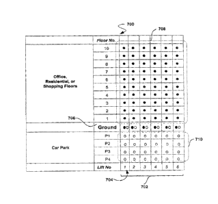
10051] Figure 7 illustrates an elevator deployment scheme 700 comprising a
zoned twin elevator system according to an aspect of the present
invention. Each of the elevator shafts, indicated by 702, include two
elevator cars (not shown) independent operating within them. As
previously described, each elevator operates within a region or zone.
For example, within each shaft (e.g., shaft 704), a first elevator car
provides transportation between the ground floor 706 and the top floor
of the building, as indicated by region 708, and designated by the dark
colored circles. Also within each shaft, a second elevator car provides
transportation from the ground floor 706 to the sub-ground level floors
of the building (i.e., floors P1-P4), as indicated by region 710, and
designated by the lighter colored circles. The sub-ground level floors,
indicated by 710, may, for exanaple, be parking levels underneath the
building. The floor levels located above ground level 706, may for
example, be residential apartments, offices, and/or commercial
shopping floors.
=
CA 02751650 2011-08-17
- 20 -
(0052) As illustrated and described in connection with Figure 6, elevator
deployment scheme 700 comprises a single ground floor level 702
(i.e., no tipper and lower ground floor level). Both the first and second
elevator cars within each shaft may load passengers from the ground
level 702. The first elevator cars operating in region 708 may load
passengers from their front doors and the second elevator cars
operating in region 710 (i.e., parking levels) may load passengers from
their rear doors. At any given instant, only one of the elevator cars
operating within each shaft can access the ground floor 702 for the
purpose of loading passengers. TA for example, the second elevator car
operating in region 710 is assigned to load passengers from the ground
floor 702 for the purpose of transporting them to the parking area, the
first elevator car operating in region 708 should remain operating at a
minimum safe distance from the second elevator car in region 708.
[0053] If the first elevator car operating in region 708 is assigned to
load
passengers from the ground floor 702, the second elevator ear should
be operating within region 710 and be located at a minimum safe
distance below the first elevator car. By operating two elevators within
a single shaft, more efficient use of the elevator shaft and, therefore,
more passenger transportation is facilitated. As illustrated in Figure 7,
while passengers are being transported to the upper floors, the elevator
shaft is simultaneously utilized for transporting our passengers to the
parking area. This deployment scheme 700 increases the traffic flow
significantly by allowing each of the twin elevator cars to operate in
two separate regions 708, 710 that have little or no overlap within each
shaft (e.g., shaft 702).
[oosq In addition to the embodiments of the aspects of the present
invention
described above, those of skill in the art will be able to arrive at a
variety of other arrangements and steps which, if not explicitly
described in this document, nevertheless embody the principles of the
CA 02751650 2013-07-29
-2 1 -
invention and fall within the scope of the appended claims. For example,
the ordering of method steps is not necessarily fixed, but may be capable
of being modified without departing from the scope of the present
invention.