Note: Descriptions are shown in the official language in which they were submitted.
CA 02751791 2011-09-06
PUMPING SYSTEM
TECHNICAL FIELD
[0001] The specification relates generally to pumping operations, and more
particularly to a fixed but movable pumping system for use in such operations.
BACKGROUND TO THE DISCLOSURE
[0002] Tailings ponds, or impoundments, can be used in mining operations and
other activities to collect refuse from the operations. Pump assemblies can be
used
to reclaim water from the tailings ponds for re-use or delivery to other
operations.
[0003] Tailings ponds experience changes in water level as new tailings and
reclaimed water, respectively, enter and leave the ponds. In addition, the
physical
geography of tailings ponds may vary as tailings build up along the shoreline.
Further, tailings ponds can be exposed to severe weather in some locations,
including wind, waves, and ice build-up. Thus, pump assemblies can be exposed
to
various conditions which may render management of the assemblies difficult and
may reduce pump uptime. In addition, the assemblies may need to be relocated
from time to time in response to the above conditions, which can further
reduce
uptime. Together, these difficulties can negatively affect the overall
performance of
the pump assembly.
SUMMARY
[0004] In a first aspect, embodiments are disclosed of a pumping system for
use
in a tailings pond, comprising: a pump support; and at least one mooring
element
coupled to the pump support, having an extended position for fixing the pump
support to a tailings pond bed, and a retracted position for permitting
movement of
the pump support towards a shore of the tailings pond; the at least one
mooring
element c onfigured for transitioning from the extended position to the
retracted
position when a distance from the shore to the pump support exceeds a pre-
determined threshold as a result of a change to tailings pond geometry, and
for
1
CA 02751791 2011-09-06
returning to the extended position following movement of the pump support to
reduce the distance below the threshold.
[0005] In certain embodiments, at least one pump is mounted to the pump
support.
[0006] In certain embodiments, the at least one mooring element is rigid.
[0007] In certain embodiments, the at least one mooring element comprises a
spud slidably supported by a spud pocket coupled to the pump support.
[0008] In certain embodiments, the pump support comprises at least one pump
barge releasably coupled to a header float, and wherein the at least one pump
is
mounted to the at least one pump barge.
[0009] In certain embodiments, the pump support comprises a plurality of pump
barges releasably coupled to the header float and wherein the at least one
pump
comprises a plurality of pumps, each of the plurality of pumps being mounted
to a
respective pump barge.
[0010] In certain embodiments, the at least one mooring element is coupled
to
the header float.
[0011] In certain embodiments, at least one walkway is coupled to the
header
float for connecting the header float to the shore.
[0012] In certain embodiments, at least one walkway comprises a flexible
floating
walkway.
[0013] In certain embodiments, the at least one walkway comprises a pair
of
walkways coupled to the header float at opposing ends of the header float.
[0014] In certain embodiments, an onshore end of each of the pair of walkways
is
configured to connect to a towing apparatus.
[0015] In certain embodiments, an inshore area of the tailings pond is
defined
between the shore, the walkways and the header float.
[0016] In certain embodiments, the at least one pump barge is coupled to
the
header float within the inshore area.
2
CA 02751791 2011-09-06
[0017] In certain embodiments, at least one of the pair of walkways is
configured
for docking one of the at least one pump barges within the inshore area when
the
one of the at least one pump barges is disconnected from the header float.
[0018] In certain embodiments, the system further comprises at least one
de-
icing apparatus for keeping the inshore area free of ice.
[0019] In certain embodiments, the at least one de-icing apparatus
comprises at
least one submersible rotary de-icer connected to the at least one pump barge.
[0020] In certain embodiments, the system further comprises an
electrical house
supported on the header float for supplying power to the at least one pump
barge.
[0021] In certain embodiments, the at least one mooring element comprises a
plurality of spuds slidably supported by a respective plurality of spud
pockets
coupled to an offshore side of the header float.
[0022] In certain embodiments, the at least one pump barge comprises a pontoon
body supporting the at least one pump, and a motor releasably operably coupled
to
the at least one pump.
[0023] In certain embodiments, the system further comprises at least one
header
pipe supported by the header float, wherein an outlet of the at least one pump
is
connected to the at least one header pipe.
[0024] In certain embodiments, the outlet is connected to the at least
one header
pipe via a discharge line releasably connected to the outlet and the at least
one
header pipe.
[0025] In certain embodiments, the system further comprises a moving apparatus
for transitioning the at least one mooring element between the extended and
retracted positions.
[0026] In certain embodiments, the at least one moving apparatus comprises
at
least one of a winch and a hydraulic cylinder.
[0027] In certain embodiments, the system further comprises an onshore crane
for manipulating the at least one pump barge.
3
CA 02751791 2011-09-06
[0028] In a second aspect, embodiments are disclosed of a pumping system for
use in a tailings pond, comprising:
a header float having an inshore side and an offshore side, the inshore and
offshore sides extending between opposing ends, the header float supporting at
least one header pipe on an upper surface thereof;
a pair of floating walkways coupled to the header float at the inshore side of
the header float adjacent to each end, each floating walkway extending
shoreward,
at least a portion of each floating walkway configured for resting onshore;
a plurality of spuds slidably coupled to the header float in one of a raised
position and a lowered position, the spuds configured to anchor the header
float to a
tailings pond floor in the lowered position; and
a plurality of pump barges connected to the header float along the inshore
side between the floating walkways.
[0029] In certain embodiments, the system of the second aspect may further
comprises any one of the features of the system of the first aspect.
[0030] Other aspects, features, and advantages will become apparent from the
following detailed description when taken in conjunction with the accompanying
drawings, which are a part of this disclosure and which illustrate, by way of
example,
principles of the inventions disclosed.
BRIEF DESCRIPTION OF THE DRAWINGS
[0031] The accompanying drawings facilitate an understanding of the various
embodiments.
[0032] Figure 1 depicts an isometric view of a fixed but movable pumping
system,
according to a non-limiting embodiment;
[0033] Figure 2 depicts an overhead plan view of the system of Figure 1,
according to a non-limiting embodiment;
4
CA 02751791 2011-09-06
[0034] Figure 3 depicts a partial overhead plan view of the system of
Figure 1,
according to a non-limiting embodiment;
[0035] Figure 4 depicts a pump barge of the system of Figure 1, according to a
non-limiting embodiment;
[0036] Figure 5 depicts the system of Figure 1 in an installed position,
according
to a non-limiting embodiment;
[0037] Figures 0-8 depict the movement of the system of Figure 1, according to
a
non-limiting embodiment;
[0038] Figure 9 depicts a partial isometric view of the system of Figure
1,
according to a non-limiting embodiment;
[0039] Figure 10 depicts a spud and spud pocket of the system of Figure 1,
according to a non-limiting embodiment; and
[0040] Figure 11 depicts a partial overhead plan view of the system of Figure
1,
according to another non-limiting embodiment.
DETAILED DESCRIPTION OF THE EMBODIMENTS
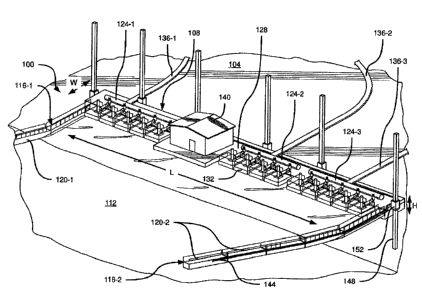
[0041] Referring to Figure 1, a fixed but movable pumping system 100 for
use in
an impoundment, or tailings pond, 104 is shown. The tailings pond 104 can
contain
waste products from a variety of processes. For example, the tailings pond 104
can
contain any one of, or any combination of, used process water, treated
wastewater
effluent, mineral flotation tailings, slurry and the like, resulting from
mining operations
and related activities. The pumping system 100 is used to reclaim water in the
tailings pond 104 from which sediment has settled out sufficiently. The water
reclaimed from the tailings pond 104 can be delivered, for example, to another
impoundment for further sedimentation, for reuse in the Mining operations,
related
activities or both, or any suitable combination of the above.
[0042] The pumping system 100 includes a pump support, to which at least one
pump can be mounted. In the present example, the pump support includes a
header
float and at least one pump barge, as will be discussed in greater detail
hereinbelow.
5
CA 02751791 2011-09-06
(0043) The pumping system 100 includes a header barge 108 (also referred to
herein as header float 108), which is a substantially rigid floating structure
which,
when in use, floats on the tailings pond 104 in proximity to the shore region
112 of
the tailings pond 104. The distance out from the shore 112 at which the header
float
108 floats on the tailings pond 104 when it is in use is not particularly
limited. In the
example shown in Figure 1, the distance from the shore 112 to the header float
108
is about 60 feet (18 metres), although it will become apparent herein that
this
distance can be varied.
[0044] The header float 108 can be constructed of any suitable material or
combination of materials, including steel and other metals, plastics,
composites
(such as fibreglass) and the like. The header float 108, in the present
example, is an
elongate, substantially rectangular float having a length, measured parallel
to the
shoreline and indicated as "L" in Figure 1, of about 240 feet (73 metres). The
header float 108 has a width 'W', measured perpendicularly to the length L, of
about
20 feet (6 metres), which does not include the widened central portion of
header
float 108, to be described below. The header float 108 also has a height, "H",
sufficient to provide about 2 feet (0.6 metres) of freeboard when it is
deployed in the
tailings pond 104. In the present example, the height H of header float 108 is
about
7 feet (2A metres). The above dimensions, as well as the substantially
rectangular
shape shown in Figure 1, are not particularly limiting, and the header float
108 can
be provided in any shape and size which satisfies the structural features of a
header
float, as discussed in greater detail below.
[0045] The header float 108 is accessible from the shore 112 via at least one
floating walkway 116. In the example shown in Figure 1, the system 100
includes
two walkways 116, labelled 116-1 and 116-2. At least a portion of each
floating
walkway 116 rests on the shore 112 when in use. A variety of configurations
are
possible for the floating walkways 116. In the present example, each floating
walkway 116 is a flexible floating walkway and comprises a plurality of
floating
walkway sections 120, labelled 120-1 and 120-2 in Figure 1. These sections 120
can be coupled end to end in any suitable manner. For example, the walkway
sections 120 can be coupled end to end by pintle connections (also referred to
as
6
CA 02751791 2011-09-06
pintle hitches). In other examples, the walkway sections 120 can be coupled by
cable or wire rope extending from one section 120 to another. Additionally,
one or
more marine buoys can be placed between connected sections 120 for shock
absorption purposes. In the present example, the sections 120 are coupled to
one
another in such a manner as to allow the walkways 116 to articulate in order
to
accommodate an upward slope of the share 112 region, extending away from the
tailings pond 104. Such articulation can be achieved by the use of hinged
connections between the sections 120. The sections 120 as shown in Figure 1
are
each about 40 feet (12 metres) in length. Thus, the walkway 116-2, which
consists
of five sections 120-2, has a total length of about 200 feet (61 metres) in
the present
example shown. It is contemplated, however, that the sections 120 can be
provided
in any other suitable length, or combination of lengths. In further
embodiments the
walkways 116 can comprise any suitable number of sections 120.
[0046] The header float 108 supports at least one header pipe 124 on an upper
surface 128 of the header float 108. The term "upper" as used herein refers to
the
orientation of surface 128 when the header float 108 is in the installed
position,
floating on the tailings pond 104. Thus, the upper surface 128 is the surface
of the
header float 108 which is substantially parallel to the surface of tailings
pond 104
and faces upwardly, away from tailings pond 104. In the present example, three
header pipes 124, labelled 124-1, 124-2 and 124-3, are supported on the header
float 108. Each header pipe 124 receives water from one or more pump barges
132
and transmits the received water to a respective discharge pipe 136. Thus,
three
discharge pipes 136-1, 136-2 and 136-3 are shown, each one corresponding
respectively to a header pipe 124-1, 124-2 and 124-3. The discharge pipes 136
carry the water dlownstream for further processing, as will be discussed
below.
[0047] A plurality of pump barges 132 are coupled to header float 108. Each
pump barge 132 comprises a discharge line, to be discussed below in greater
detail,
which is connected to one of the header pipes 124. In some examples, each pump
barge 132 can be connected to a header float 108 solely by way of the
connection
between the pump barge 132 and the respective header pipe 124. In other
examples, an additional coupling can be provided between each pump barge 132
7
CA 02751791 2011-09-06
and header float 108 for further stability. In the present example, fourteen
pump
barges 132 are provided (not all of these are labelled, to maintain legibility
in Figure
1). Specifically, five pump barges 132 are connected to header pipe 124-1,
four
additional pump barges 132 are connected to the header pipe 124-2, and five
further
pump barges 132 are connected to the header pipe 124-3. The example
arrangement shown in Figure 1 is not particularly limiting, and a wide variety
of
arrangements of pump barges 132 and header pipes 124 can be implemented,
depending on the pumping requirements to be satisfied by the system 100. For
example, if the discharge pipe 136-2 required a greater flow rate, the header
pipe
124-2 could be modified to accommodate a larger number of pump barges 132.
[0048] The header float 108 can also support, on the upper surface 128, an
electrical house 140. The electrical house 140 is supplied with electrical
power from
onshore facilities (not shown) by way of cabling 144 which is carried to the
header
float 108 on a walkway 116. In the example shown in Figure 1, the walkway 116-
2
includes a cable tray for the cabling 144. In other examples, it is
contemplated that
more than one walkway can be used to carry the cabling 144. The electrical
house
140 contains the required facilities to supply the pump barges 132 with
electrical
power. The electrical house 140 can also contain control mechanisms for
controlling
the operation (e.g. flow rate) of each pump individually. In other examples,
such
mechanisms can be located on the individual pump barges 132.
[0049] The pumping system 100 also includes at least one mooring element
coupled to the pump support. In the present example, the at least one mooring
element is coupled to header float 108 The at least one mooring element can be
a
rigid mooring element, such as a spud, as will be discussed in greater detail
below.
[0050] Also shown in Figure 1 there is depicted a plurality of spuds 148. Each
spud 148 is slidably supported within a spud pocket 152 coupled to the header
float
108, such that when header float 108 is in use (that is, deployed in tailings
pond
104), the spuds 148 are slidable between retracted (also referred to herein as
"raised") and extended (also referred to herein as "lowered") positions, with
the
lowered positions resulting in the spuds 148 being embedded within, or at
least
8
CA 02751791 2011-09-06
abutted against, the bottom of the pond 104. In the raised position, the spuds
148
do not engage the bottom of the pond 104, and thus allow the header float 108
to be
relocated within pond 104. The spud pockets 152 are coupled to the header
float
108 along one or more sides of said header float 108. The spud pockets 152 can
be
coupled to header float 106 in fixed permanent positions, for example by
welding or
other permanent fastening, or can be temporarily fixed in position along the
sides of
the header float 108. For example, the spud pockets 152 can themselves be
slidable along a rail (not shown) extending around the sides of header float
108.
[0051] In the example shown in Figure 1, six spuds 148 are provided with
the
header float 108. In the present example, the use of between four and six
spuds
148 is contemplated. However, any suitable number of spuds may be provided, to
accommodate various shapes and sizes of header float 108 and various operating
environments (e.g. wind and wave loading in the tailings pond 104). The
operation
of the spuds 148 will be discussed in greater detail below.
[0052] Turning to Figure 2, an overhead plan view of the pumping system 100 is
shown. From Figure 2 it can be seen that the header float 108 has an inshore
side
200, an offshore side 204, and opposing ends 208. The terms "inshore" and
"offshore" as used herein refer to the orientation of the header float 108
when
deployed in the tailings pond 104. Thus, the inshore side 200 is the side of
the
header float 108 which is closest to the shore 112 when the header float 108
is
deployed in the pond 104. The offshore side 204 is the side of the header
float 108
furthest from the shore 112 when the header float 108 is deployed in the pond
104.
While the inshore side 200 and the offshore side 204 are substantially
parallel to one
another and to the shore 112 in the present example, they need not be
substantially
parallel to one another or to the shore 112, so long as the inshore side 200
generally
faces the shore 112 when the header float 108 is deployed in the pond 104. In
the
present example, the ends 208 are substantially perpendicular to the sides
200, 204,
though this arrangement is also not strictly necessary.
[0053] The two walkways 116-1 and 116-2 are coupled to the header float 108
along the inshore side 200 adjacent to the ends 208. That is, the walkway 116-
1 is
9
CA 02751791 2011-09-06
coupled adjacent to one end 208, while the other walkway 116-2 is coupled
adjacent
to the opposite end 208. The nature of the coupling between the walkways 116
and
the header float 108 is not particularly limited. For example, the walkways
may be
coupled to the upper surface 128 at the side 200, or they may be coupled to a
side
surface (not visible in Figure 2) perpendicular to the upper surface 128, or
to both of
the above-mentioned surfaces. The walkways 116 need not be anchored or
otherwise connected to any structures on the shore 112, as is shown in Figure
2.
Rather, the portions of the walkways 116 which extend onto the shore 112 can
rest
on the shore 112 but remain movable, as will be discussed in greater detail
below.
[0054] As shown in Figure 2, when the header float 108 is deployed in the pond
104 and the walkways 116 are coupled to the header float 108, a substantially
enclosed inshore space 212 within pond 104 is defined by the header float 108,
the
walkways 116 (the portions of which lie between the header float 108 and the
shore
112, it will be recalled, float in tailings pond 104) and the shore 112. The
pump
barges 132 are coupled to the header float 108 within the inshore space 212.
In
other words, each one of the pump barges 132 is coupled to the header float
108
along the inshore side 200 and between the walkways 116. As with the walkways
116, the particular manner of coupling the pump barges 132 to the header float
108
is not particularly limited.
[0055] Cabling 144 is also shown in Figure 2 travelling along the walkway 116-
2
onto the header float 108 and to the electrical house 140. Additional cabling
(not
shown) is provided between the electrical house 140 and each pump barge 132
for
supplying power to the pump barges 132. It is contemplated that the cabling
144
originates from onshore facilities (not shown) before travelling onto the
walkway 116-
2 towards the header float 108.
[0056] Also shown in Figure 2 is the positioning of spuds 148 and the spud
pockets 152. Each of the six provided spuds 148 is mounted along the offshore
side
204 and the ends 208 of the header float 108. It is contemplated, however,
that
other arrangements can also be implemented. For example, one or more spuds 148
CA 02751791 2011-09-06
(and corresponding spud pockets 152) can be coupled to the header float 108
along
the inshore side 200 instead of the offshore side 204 or the ends 208.
[0057] The discharge pipes 136 each direct water from the pump barges 132 to a
transfer station 216 on the shore 112. The discharge pipes 136 can be
configured to
float on the surface of the tailings pond 104 as they travel from the header
float 108
to the shore 112 (as shown in Figure 5, to be discussed further below). In
other
examples, the discharge pipes 136 can travel underneath the surface of the
tailings
pond 104, such as along the bottom of the tailings pond 104. From the transfer
station 216, water can then be provided to further downstream facilities. In
some
examples, the transfer station 216 can be omitted and the discharge pipes 136
can
travel directly to the various downstream facilities to which water from the
tailings
pond 104 is to be delivered.
(0058] Turning now to Figure 3, a partial overhead view of the pumping system
100 is shown. As will be discussed in greater detail below, each pump barge
132
can be disconnected from the header float 108 independently of the other pump
barges 132. Thus, a first pump barge 132-1 is shown having recently been
disconnected from the header float 108 and floating within the space 212. A
second
pump barge 132-2 is positioned within the space 212 to be connected to the
header
float 108 in place of the pump barge 132-1. Thus, individual pump barges 132
can
be removed, added and replaced on the header float 108 without interrupting
the
operation of the remainder of the pumping system 100. The manipulation of the
pump barges 132 within the space 212 can be carried out by a crane 300
provided
on the shore 112 in proximity to the space 212. In the present example, the
crane
300 is located on the outside walkways 116 at a distance from the pond 104
which
allows the crane 300 to reach any particular pump barge 132 connected to the
header float 108 or floating within the space 212. In other examples, shore-
based
winches (not shown) can be used instead of, or in addition to, the crane 300
for
manipulating pump barges 132 within the space 212.
[00591 As is also shown in Figure 3, at least one of the walkways 116 can be
configured for docking one or more pump barges 132 within the inshore area 212
11
CA 02751791 2011-09-06
when the pump barge 132 is disconnected from the header float 108. In
particular, a
pump barge 132-3 is coupled to a dock 304 of the walkway 116-2 in order to
provide
access to the pump barge 132-3 from the walkway 116-2, for example to conduct
maintenance on the pump barge 132-3.
[0060] Referring now to Figure 4, a pump barge 132 is shown in greater
detail.
The pump barge 132 can be a pontoon-style barge, and thus includes a pontoon
body 400 of any suitable material or combination of materials, including steel
and
other metals, plastics, composites (such as fibreglass) and the like. In the
present
example, the pontoon body 400 is dimensioned in order to support the
components
of the pump barge 132 in the tailings pond 104 while maintaining at least
about two
feet (0.6 metres) of freeboard. It is contemplated that in other examples,
greater or
smaller levels of freeboard may be desirable, and the dimensions of the
pontoon
body 400 may be modified accordingly. The dimensions of body 400 are therefore
not particularly limited.
[0061] The body 400 of the pump barge 132 supports a pump 404, which can be
a vertical turbine pump ("VIP") having an inlet 408 extending downwardly from
a
lower surface of the body 400 into the pond 104 when the pump barge 132 is
deployed. Water from the pond 104 is drawn into the inlet 408 during the
operation
of the pump 404, and expelled from the pump 404 via an outlet 412, which is
connected to a flexible discharge line 416. The pump 404 is removably coupled
to a
flexible discharge line 416 at the outlet 412 by way of a quick disconnect
fitting (for
example, fittings such as those manufactured by Victaulic Company). A flexible
discharge line 416, in turn, is connected to one of the header pipes 124 (not
shown
in Figure 4) when the pump barge is deployed alongside the header float 108.
The
connection between the discharge line 416 and the header pipe 124 can also be
a
quick disconnect fitting. Thus, the pump barge 132 can be readily connected to
and
disconnected from the header float 108.
[00621 The pump 404 is driven by a motor 420 which is releasably operably
coupled to the pump 404 (that is, coupled to pump 404 in a releasable manner
which
permits the motor 420 to drive the pump 404). In the present example, the
motor
12
CA 02751791 2011-09-06
420 is supported by the pump 404 above and substantially coaxially with the
pump
404. However, it is contemplated that various arrangements of the pump 404 and
the motor 420 can be implemented to accommodate the specifications of the pump
404 and the motor 420. The nature of the motor 420 is not particularly
limited. In
the present example, the motor 420 is a 250HP motor with a quick disconnect
fitting
for connecting to the pump 404.
[00631 In operation, the flow rate of the pump 404 can be between about 2500
gallons per minute (gpm) and 6600 gpm in the present example. In other
examples,
it is contemplated that a wide variety of specifications for the pump 404 and
the
motor 420 can be selected depending on the particular operating environment of
the
pumping system 100. Other flow rates are therefore also contemplated.
[0064] The pump barge 132 can also include a skid frame 424 (e.g. a steel skid
frame) mounted on the lower surface of the body 400 for enabling the pump
barge
132 to rest and to move along a surface (e.g. the shore 112 or a transport
vehicle,
not shown) without damaging the body 400. The term "lower is used herein to
refer
to the surface of the body 400 (and more generally, to any surface discussed
herein)
which, when the pump barge 132 is deployed in the pond 104, it is
substantially
parallel to the surface of pond 104 and faces towards the bottom of pond 104.
The
skid frame 424 can be coupled to the body 400 by way of any suitable fasteners
or
combination of fasteners, including welds, bolts, screws and the like. In
other
examples, the skid frame 424 can be omitted.
[0065] Additionally, the pump barge 132 can include at least one de-icing
apparatus. In the present example, each pump barge 132 includes one or more
submersible rotary de-icers 428. Each de-icer 428 can be suspended from the
body
400, and includes a motor (for example, a 120V, 1HP motor) driving a propeller
(not
shown) for circulating water towards the surface of pond 104 in proximity to
the body
400 of the pump barge 132. In the present example, four de-icers 428 are
suspended from each pump barge body 400, though this number is not
particularly
limiting ¨ any suitable number of de-icers can be included. In some examples,
de-
icers can be omitted entirely (for example, in operating environments without
the risk
13
CA 02751791 2011-09-06
of ice formation, or where other de-icing means are provided) or coupled to
the
header float 108 rather than pump barges 132. The pump barge 132 can also
include a safety railing 432. it is also contemplated that the pump barge 132
includes one or more electrical connections (not shown) for receiving power
from the
6 electrical house 140 in order to power both the motor 420 and the de-
icers 428.
[0066] Turning now to Figure 5, the operation of the pumping system 100 will
be
discussed in greater detail. The pumping system 100 is shown installed in a
fixed
position in the tailings pond 104. Thus, the header float 108 is deployed in
the pond
104 in proximity to the shore 112 (at a selected first distance from shore
112), and
the walkways 116 (of which the walkway 116-2 is visible in Figure 5) are
coupled to
the header float 108 and resting partly on the shore 112. As shown in Figure
5, the
sections 120 of the walkway 116-2 are articulated such that a first section
120
coupled to the header float 108 floats in the pond 104 substantially parallel
to the
surface of the pond 104, while the remaining sections 120 rest on the shore
112
accommodating the slope of the shore 112 (which, in the present example, may
be a
slope of about 4:1).
[0067] As noted above, the pumping system 100 as shown in Figure 5 is in a
fixed position. That is, the spuds 148 are in the extended, or lowered,
position and
at least a portion of each spud 148 is embedded within the bed of the tailings
pond
104 to fix the header float 108 to the tailings pond bed. The spuds 148, in
the
present example, are about 75 to 90 feet (22.9 to 27.4 metres) in length,
though it is
contemplated that other spud lengths may be used to accommodate various
tailings
ponds 104. The depth to which the spuds 148 penetrate into the bottom of the
pond
104 is between 3 feet and 25 feet (1 to 7.5 metres), depending on the nature
of the
material on the bottom of the pond 104. In general, the harder the material,
the
smaller the penetration depth of the spuds 148. In the deployed position shown
in
Figure 5, the tailings pond 104 is at a first level, indicated as "PL" or
"Pond Level". In
the present example, PL is about 20 feet (6.1 metres), though it will now be
appreciated that this level is provided purely for illustrative purposes.
14
_ _
CA 02751791 2011-09-06
[00681 Turning to Figure 6, over time additional tailings 600 may build
up on the
bottom of the tailings pond 104. As shown in Figure 7, the result of such
build-up is
that the level PL increases over time to level PL'. In the present example, it
is
assumed that the level PL increases by about 15 feet (4,6 metres) per year,
though
it is contemplated that a wide variety of rates of increase are possible.
Thus, in the
present example, the level PL' is greater than the level PL by about 15 feet.
[0069] As a result of the increased level of the pond 104, the header float
108
and the pump barges 132 have risen with the surface of the pond 104, and due
to
the slope of the shore 112, are now located a second distance from that shore
112,
which is greater than the first distance shown in Figure 5. More generally,
changes
in the geometry of the tailings pond 104 (including, but not limited to, the
above-
mentioned increase in the level PL) can result in the distance between the
header
float 108 and the shore 112 exceeding a threshold distance beyond which it is
undesirable for the header float 108 to be located. A wide variety of
threshold
distances are contemplated. For example, the threshold distance can be double
the
first distance shown in Figure 5 (which may be the optimal or desired distance
between the shore 112 and the header float 108). In order to maintain the
distance
between the header float 108 and the shore 112, the header float 108 must
therefore
be moved. This is accomplished by raising or retracting (that is,
transitioning to the
retracted position), the spuds 148 from the bottom of the pond 104. The spuds
148
can be raised, for example, by winches or by a crane (not shown) mounted on
the
header float 108, and are shown in Figure 7 in the raised position.
[00701 Following the raising of the spuds 148 to the raised position,
the pumping
system 100 is moved such that the header float 108 and the pump barges 132 are
displaced along the surface of the pond 104. Such a displacement can be
accomplished by way of a towing apparatus, such as earth moving equipment
(e.g.
one or more bulldozers 704), coupled to the onshore end 700 of the walkways
116 in
order to pull walkways 116 up the shore 112, thereby pulling the header float
108
and the pump barges 132 along the surface of the pond 104 towards the shore
112.
In some examples, the action of the earth moving equipment can supplemented
with
CA 02751791 2011-09-06
winches (not shown) mounted to one of the header float 108 and the shore 112
and
coupled to the other of the header float 108 and the shore 112.
[00711 The system 100 is moved as described above until the header float 108
is
once again located at the first distance (that is, the distance shown in
Figure 5) from
the shore 112 or at least until the header float 108 is located at a distance
that is
below the threshold distance from the shore 112. The movement and final
placement of the pumping system 100 is shown in Figure 8. Once the movement is
completed, the spuds 148 can be released and transitioned to the lowered
position,
anchoring the header float 108 within the tailings pond 108. In the present
example,
the lowering of the spuds 148 is accomplished by free-fall, such that the
weight of
the spuds 148 drives the spuds 148 into the bottom of the tailings pond 104.
In
other examples, the lowering of the spuds 148 can be controlled, or assisted,
by a
winch or a crane (not shown).
[0072] The above procedure can be repeated as needed, or at scheduled
intervals, or a combination of both. For example, the pumping system 100 may
be
scheduled for moving and fixing in the above-described manner once per year,
and
may also be moved and fixed on an ad-hoc basis when the level of the tailings
pond
104 rises more quickly than anticipated, It is also contemplated that the
system 100
can be moved to accommodate decreases in the level PL of the pond 104. In such
instances, earth moving equipment can be used to push the walkways 116 down
shore 112, thus pushing the header float 108 and the pump barges 132 out into
the
pond 104. The movement of the system 100 away from the shore 112 may be
necessary in response to either or both of decreases in the level PL of the
pond 104,
and a build up of tailings on the shore 112, which effectively brings the
shore 112
closer to the header float 108.
[0073] In summary, therefore, also provided herein is a method of
relocating a
fixed but movable pumping system 100. The method includes raising the spuds
148
from a lowered position to a raised position, thus releasing the header float
108 from
the bottom of the tailings pond 104. The method also includes coupling a
towing
apparatus, including at least one piece of earth moving equipment, to one or
more of
16
CA 02751791 2011-09-06
the walkways 116. The method further includes, following the raising of the
spuds
148 and the coupling of the towing apparatus, displacing system 100 along the
shore 112 and the surface of the tailings pond 104 using the towing apparatus.
The
method further includes lowering the spuds 148 to the lowered position, in
which the
spuds 148 once again anchor the header float 108 within the tailings pond 104.
in
some examples, the method can also include raising and lowering the spuds 148
without moving the header float 108. Raising and lowering the spuds 148 in
place at
intervals more frequent than the interval at which the pumping system 100 is
moved
can reduce the hoisting forces associated with the suction effect when the
material
of the bottom of the pond 104 is soft
[00741 Referring now to Figure 9, a partial view of the system 100 is
provided in
which certain components of the system 100 are shown in greater detail.
Specifically, the discharge lines 416 of the pump barges 132 are seen as
connected
to the fittings 900 on the header pipes 124.
16 [0075] Referring to Figure 10, a detailed view of a spud 148 and a
corresponding
spud pocket 152 is shown. The spud pocket 152 includes a channel defined
therethrough, in which the spud 148 is supported and allowed to slide in
opposing
directions "A" and "B" between raised and lowered positions. The spud pocket
152
can include one or more rollers 1000 having axes of rotation perpendicular to
the
directions of travel of the spud 148. The rollers 1000 allow for reduced
friction
between the spud 148 and the spud pocket 152 during movement of the spud 148.
It is also contemplated that when the spuds 148 are in the lowered position
(and are
therefore fixed, or substantially fixed, to the bottom of the pond 104),
rollers 1000
allow the spud pockets, and by association the header float 108, to travel
upwards
and downwards along the spud 148 to accommodate the rise and fall of the
surface
of the tailings pond 104. The travelling of the header float 108 along the
spuds 148
can precede the situation illustrated in Figure 7 (e.g. before the level PL
has reached
the level PL'). In other words, the above-mentioned travelling can accommodate
certain variations in the level PL of pond 104 without requiring movement of
the
pumping system 100. In other examples, rollers 1000 can be omitted and each
spud
17
CA 02751791 2011-09-06
pocket 152 can provide at least one internal bearing surface upon which spud
148
can slide.
[0076] The raising of the spuds 148 is accomplished by way of a winch 1004
mounted on an upper surface 128 of the header float 108. The winch 1004 can be
coupled to a cable (not shown) which Is in turn is coupled to the spud 148,
and can
thus be used to raise the spud 148. The lowering of the spuds 148 in the
present
example can be accomplished by disengaging the winch 1004 such that the spud
148 enters free-fall in the direction "A". In other examples, the winch 1004
can be
used to moderate the descent of the spud 148, or additional equipment (not
shown)
can be used to assist the descent of the spud 148. For example, a hydraulic
apparatus (such as a hydraulic cylinder, not shown) may be connected to the
spud
148 and operated to drive the spud 148 into the bottom of the pond 104. In
some
examples, such a hydraulic apparatus may replace the winch 1004; that is, the
winch 1004 may be omitted entirely, and the hydraulic apparatus may be used to
both raise and lower the spud 148.
[0077] Certain advantages will now be apparent to those skilled in the art
from
the above description. For example, the coupling of the walkways 116 near the
ends
208 of the header float 108, and the coupling of pump barges 132 along the
inshore
side 204 of the header float 108, allow the pump barges 132 to be protected
from
heavy wind, waves, and moving ice, while also allowing for easy access to the
pump
barges 132 from shore (via crane 300, for example) for maintenance purposes.
Ready access to the pump barges 132 from the shore 112 allows maintenance and
replacement of the pump barges 132 at the header float 108 to be carried out
rapidly, reducing the pump downtime.
[0078] Another exemplary advantage provided by the pumping system 100 as
described above is that the construction (and eventual re-construction, in
response
to increases or decreases of the level PL of the pond 104) of concrete piles
on shore
112 and in the tailings pond 104 in order to anchor the pumping system 100 can
be
avoided.
18
CA 02751791 2011-09-06
[00791 A further exemplary advantage provided by the pumping system 100 is
that individual pump barges 132 can be replaced, removed and added to the
pumping system 100 as necessary, without affecting the remaining pump barges.
Thus, the overall performance of the pumping system 100 (for example, measured
in
terms of pumping capacity) can remain substantially consistent despite changes
to
the system 100, such as the replacement of some pump barges 132. An additional
exemplary advantage provided by the system 100 is that the pump barges 132 may
remain operational during the relocation of the pumping system 100, further
reducing
downtime. Other advantages may also occur to those skilled in the art.
[0080] Variations to the pumping system 100 as described above are also
contemplated. For example, in some variations, an electrical house 140 can be
omitted from the header float 108. In such examples, the electrical house 140
can
instead be located on the shore 112.
[0081] In other example variations of the pumping system 100, three or more
walkways 116 may be provided, for example when the header float 108 exceeds a
certain length in order to allow to ready access to all portions of the header
float 108
from the shore 112. In further variations, the walkways 116 can be omitted
entirely.
[0082] In additional variations, as shown in Figure 11, the dock 304 can
be
omitted from walkways 116. Further, an onshore crane 1100 can be provided
between the walkways 116, rather than the crane 300 which was provided outside
of
the walkways 116.
[0083] In further variations, the header pipes 124 can be omitted from
the header
float 108 and instead be provided on the shore 112. In such variations, the
discharge lines 416 from the pump barges 132 can extend to the shore 112
before
connecting to the header pipes 124.
[0084] In still further variations, the pump support of the pumping
system 100 can
be a single barge rather than the header float 108 and the pump barges 132. In
these variations, such a monolithic barge can support an electrical house such
as
the electrical house 140, as well as a pump house which contains at least one
pump
mounted to the monolithic barge. The walkways 116, header pipes 124, spuds
148,
19
CA 02751791 2014-04-07
de-icers 428 and the like can be connected to the monolithic barge or omitted,
as
described above.
[0085] In the foregoing description of certain embodiments,
specific terminology
has been resorted to for the sake of clarity. However, the disclosure is not
intended
to be limited to the specific terms so selected, and it is to be understood
that each
specific term includes other technical equivalents which operate in a similar
manner
to accomplish a similar technical purpose. Terms such as "left" and right",
"front"
and "rear", "above" and "below" and the like are used as words of convenience
to
provide reference points and are not to be construed as limiting terms.
[0086] In this specification, the word "comprising" is to be understood in
its "open"
sense, that is, in the sense of "including", and thus not limited to its
"closed" sense,
that is the sense of "consisting only of'. A corresponding meaning is to be
attributed
to the corresponding words "comprise", "comprised" and "comprises" where they
appear.
[0087] The scope of the claims should not be limited by the preferred
embodiments set forth above, but should be given the broadest interpretation
=
consistent with the description as a whole.
[0088] Also, the various embodiments described above may be implemented in
conjunction with other embodiments, e.g., aspects of one embodiment may be
combined with aspects of another embodiment to realize yet other embodiments.
Further, each independent feature or component of any given assembly may
constitute an additional embodiment.