Note: Descriptions are shown in the official language in which they were submitted.
WASTE CONTAINER WITH IMPROVED LATCH
100011 Continue to [0002].
BACKGROUND
[0002] Waste containers, such as for trash, recycling, or organic waste
(compost),
etc., often attract the interest of animals, such as rodents, dogs, raccoons,
etc. Many containers
include lids that latch, but some animals can pry under the lid and force the
container open.
[0003] For areas where the collection trucks include cart lifters, the
containers might
become damaged if they are lifted and dumped while latched.
SUMMARY
[0004] A waste container includes a body having a base and a side wall
extending
upward from the base to define a container interior. A lid is hingeably
secured to an upper
portion of the side wall. A latch assembly selectively secures the lid to the
side wall, the latch
assembly including a rotatable latch portion having a latch member selectively
interlocking with
a hook portion.
100051 In an independent feature, the body includes a lip projecting
outward from the
upper portion of the side wall and an outer rib protrudes upward from the lip.
The outer rib is
outward of the lid, to prevent animals from prying under the lid.
1
CA 2751829 2017-08-16
CA 02751829 2011-09-07
BRIEF DESCRIPTION OF THE DRAWINGS
[0006] Figure 1 is a front perspective view of a waste container
according to one
embodiment.
[0007] Figure 2 is a rear perspective view of the container of Figure 1.
[0008] Figure 3 is a top view of the container.
[0001] Figure 4 is a front view of the container.
[0002] Figure 5 is a side view of the container.
[0003] Figure 6 is an exploded view of the container.
[0004] Figure 7 is an interior perspective view of half of the container
body.
[0005] Figure 8 is an exterior perspective view of the container body
half of Figure 7.
[0006] Figure 9 is a perspective view of the lid and latch assembly of
Figure 1 in an
unlocked position.
[0007] Figure 10 is a perspective view of the lid and latch assembly of
Figure 1 in a
locked position.
[0008] Figure 11 is a perspective view of the lid without the latch
assembly.
[0009] Figure 12 is a bottom perspective view of the lid of Figure 11.
[0010] Figure 13 is a top view of the lid of Figure 11.
[0011] Figure 14 is a bottom perspective view of the upper and lower
latch portions.
[0012] Figure 15 is a perspective view of the upper latch portion.
[0013] Figure 16 is a perspective view of the lower latch portion
engaging the body.
[0014] Figure 17 is a perspective view of the lower latch portion and
body of Figure
16 in an unlocked position.
[0015] Figure 18 is a perspective view of the lower latch portion.
2
[0016] Figure 19 is a bottom perspective view of the lower latch
portion.
10017] Figure 20 is a bottom perspective view, broken away, of the
container with the
latch assembly in the locked position.
[0018] Figure 21 is a perspective view of an upper portion of an
alternate body that
could be used in the container of Figures 1-20.
100191 Figure 22 shows the body of Figure 21 with the lid and latch
assembly.
[0020] Figure 23 is a section view through the lid and body of Figure
22.
[0021] Figure 24 is an exploded, bottom perspective view of an
alternative upper
latch portion and alternative lower latch portion.
[0022] Figure 25 is a perspective view of the lower latch portion of
Figure 24.
[0023] Figure 26 is a bottom perspective view, broken away, of the
container with the
alternative latch assembly of Figure 24 in the locked position.
DETAILED DESCRIPTION OF A PREFERRED EMBODIMENT
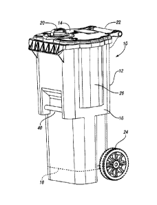
[0024] A container, such as a roll out cart 10, according to one
embodiment of the
present invention is shown in Figures 1 and 2. The roll out cart 10 generally
includes a container
body 12 and a lid 14 pivotably connected to the container body 12 for
selectively providing
access to an interior of the container 12. The container body 12 includes a
side wall 16
extending upwardly from a base 18 to define the container interior. A latch 20
selectively
prevents the lid 14 from opening. In Figure 1, the latch 20 is shown in the
latched (locked)
position, in which the lid 14 cannot be opened.
[0025] The roll out cart 10 may include a handle 22 and wheels 24 to
facilitate
moving the roll out cart 10. The side walls 16 of the container body 12
includes expanded
3
CA 2751829 2017-08-16
CA 02751829 2011-09-07
portions 26 (one is shown in Figure 1 and the other is shown in Figure 2) to
facilitate the roll out
cart 10 being grasped by cart lifters. The roll out cart 10 may further
include a grab bar 40 at a
front of the container body 12 to further facilitate use with handling
equipment, such as a cart
lifter.
[0026] Figure 3 is a top view of the roll out cart 10. The latch 28 is
rotatable relative
to the lid 14. Locked indicia 30 and unlocked indicia 32 may be molded into
the upper surface
of the lid. When the handle 28 of the latch 20 is rotated into alignment with
the locked indicia
30, this indicates that the latch 20 is locked and the lid 14 cannot be
opened. When the handle 28
of the latch 20 is rotated into alignment with the unlocked indicia 32, this
indicates that the latch
20 is unlatched and the lid 14 can be opened.
[0027] Figure 4 is a front view of the roll out cart 10. Figure 5 is a
side view of the
roll out cart 10.
[0028] Figure 6 is an exploded view of the roll out cart 10. The latch
20 includes the
handle 28 as part of an upper latch portion 21. A pair of hinge pins 34
pivotably connect the lid
14 to the handle 22, which is integrally molded with the container body 12.
The latch 20 further
includes a generally disc-shaped lower latch portion 36 below the lid 14 and
secured to the upper
latch portion 21 via a lock pin 38. The grab bar 40, wheels 24 and wheel axle
42 are also shown
in Figure 6.
[0029] Figure 7 is a perspective view of half of the container body 12.
As shown, the
grab bar 40 does not extend into the interior of the container body 12. As a
result, there are no
holes through the side wall 16 or base 18, which prevents leakages. The
corners of the side walls
16 include large blends to make it easier for waste to empty out and to make
the container body
4
CA 02751829 2011-09-07
12 easier to clean. A lower rear portion of the container body 12 includes a
reinforced area
which carries the axle for the wheels 24.
[0030] Figure 8 is an external view of thc half of the container body of
Figure 7.
[0031] Figure 9 is a perspective view of the lid 14, showing the latch
20 rotated to the
unlocked position, in which the handle 28 is aligned with the unlocked indicia
32. The latch 20
further includes a pair of indicators 44, which are aligned with the handle
28, to further provide
an indication of the position of the latch 20 relative to the indicia 30, 32.
[0032] Figure 10 shows the lid 14 with the latch 20 rotated such that
the handle 28
and indicators 44 are aligned with the locked indicia 30.
[0033] Figure 11 shows the lid 14 with the latch 20 removed. The lid 14
includes a
raised inner annular portion 50 circumscribing an opening through the lid 14.
A second outer
annular portion 48 is lower than the inner annular portion 50 but higher than
the surrounding
portions of the lid 14. The raised annular portions 48, 50 assist in
preventing water and dirt from
intruding into the latch area.
[0034] Figure 12 is a bottom perspective view of the lid 14. The lid 14
includes a
lower annular portion 51 protruding downwardly around the opening through the
lid 14. An
outer lip 52 protrudes downwardly around the periphery of the lid 14. An inner
lip 53 protrudes
downwardly and is spaced inwardly of the outer lip 52. The spaced apart
peripheral lips 52, 53
add strength to the lid 14 and help reduce odor from leaving the interior of
the roll out cart 10.
100351 Figure 13 is a top view of the lid 14 with the latch removed.
[0036] Figure 14 is bottom perspective view of the upper portion 21 of
the latch 20.
The upper portion 21 of the latch 20 includes a lower annular portion 54 and a
shaft 56
CA 02751829 2011-09-07
protruding downwardly of the lower annular portion 54. An opening 58 for
receiving the locking
pin 38 is formed near a lower end of the shaft 56.
[0037] Figure 15 is an upper perspective view of the upper portion 21
of the latch 20.
[0038] Figure 16 shows the container body 12 with the lower portion 36
of the latch
20 in position in the locked position. Referring to Figure 18, the lower
portion 36 is generally
disc-shaped and includes large diameter portions 60 and small diameter
portions 62. Notches are
defined between the large diameter portions 60, outward of the small diameter
portions 62. In
this example, the large diameter portions together occupy approximately 2/3 of
the
circumference of the lower latch portion 36, while the two opposed small
diameter portions 62
together comprise approximately the remaining 1/3 of the circumference of the
lower latch
portion 36 (approximately 60 each). Alternatively, a single small diameter
portion 62 could be
provided. Further, alternatively, the larger diameter portions 60 and small
diameter portions 62
could have different relative sizes, depending upon the application or
depending upon user
preferences.
[0039] Sweeper ribs 70 protrude upwardly between adjacent larger
diameter portions
60 and small diameter portions 62. The sweeper ribs 70 extend radially
outwardly from an upper
generally cylindrical portion 66 having an opening formed therein, which is
complementary to
the shaft 56 of the upper latch portion 21. The sweeper ribs 70 clean out
waste that may get into
the latch area during rotation of the handle 28. A latch member 64 protrudes
downwardly and
radially inwardly from an outer periphery of the larger diameter portions 60
of the lower latch
portion 36. As shown, the latch member 64 may be arcuate.
[0040] As shown in Figure 19, a lower annular portion 72 protrudes
downwardly of
the lower latch portion 36, and includes a central opening therethrough
complementary in shape
6
CA 02751829 2011-09-07
to the shaft 56 of the upper latch portion 21. The lower annular portion 72
further includes a
transverse opening for receiving the latch pin 38.
[0041] As shown in Figure 17 and 20, a forward facing hook 68 is formed
adjacent an
upper edge of the container body 12. The hook 68 engages the latch member 64
of the latch
lower portion 36 thus, latching the lid 14 to the container body 12. The latch
assembly includes
the upper latch portion 21, lower latch portion 36 and hook 68. As also shown
in Figure 20, the
shaft 56 of the upper latch portion 21 is received through the opening in the
lid 14 and through
the opening in the lower annular portion 72 in the lower latch portion 36 and
secured there with
the locking pin 38.
[0042] In use, a user places waste in the container body 12 and rotates
the handle 28
of the latch 20 about an axis generally transverse to the lid 14 to the locked
position, in which the
handle 28 is aligned with the locked indicia 30. This latches the lid 14 to
the container body 12
as shown in Figure 20. This prevents rodents or other animals from accessing
the contents of the
roll out cart 10. The latch assembly is more durable and resistant to being
pried open than
previous latches. On waste pick-up day, the user can wheel the roll out cart
10 to the curb and
then rotate the handle 28 of the latch 20 to the unlocked position, where the
hook 68 on the
container body 12 would be aligned with one of the smaller diameter portions
62 of the lower
latch portion 36. When the driver of the waste truck arrives, the driver can
see whether the lid 14
is locked or unlocked. If the lid 14 is unlocked, the driver can use the cart
lifter on the truck (e.g.
using the grab bar 40 and/or portions 26 of the side walls 16) to lift the
roll out cart 10 and dump
the contents into the truck. If the driver sees that the handle 28 of the
latch 20 is still in the
locked position, the driver will not attempt to dump the cart 10 while the lid
is latched.
7
CA 02751829 2011-09-07
100431 Figures 21-23 illustrate an alternative container body 112 for
use with the lid
14 of Figures 1-20. Referring to Figure 21, the container body 112 includes a
side wall 116 and
an upper lip including an upper lip wall 176 extending outwardly from an
uppermost edge of the
side wall 116 and a flange 178 extending downwardly from an outermost edge of
the upper lip
wall 176. The lip includes an apron portion 180 projecting forwardly and
downwardly from the
front of the container body 112 in front of the hook 168. An inner rib 182
projects upwardly
from an inner periphery of the upper lip wall 176. An outer rib 184 projects
upwardly from the
side edges of each outer periphery of the upper lip wall 176. The outer rib
184 is taller than the
inner rib 182. The outer rib 184 extends generally from the handle 122 to the
apron portion 180.
[0044] Figure 22 shows the lid 14 of Figures 1-20 on the alternative
container body
112. Figure 23 is a section view through one side of the container body 112
and lid 14.
Referring to Figures 22 and 23, the outer lip 52 of the lid 14 contacts the
upper lip wall 176 of
the container body 112 between the inner rib 182 and the outer rib 184. The
inner lip 53 of the
lid 14 is received inward of the inner rib 182.
[0045] In use, the outer rib 184 prevents rodents from being able to pry
under the lid
14. The outer rib 184 is not necessary near the handle 122 because that is
where the lid 14 is
attached to the container body 112. Similarly, the outer rib 184 is not
necessary near the latch 28
because the lid 14 is also attached to the container body 112 there.
100461 An alternate latch 220 is shown in Figures 24-26. The latch 220
includes an
upper latch portion 221 and a lower latch portion 236. The upper latch portion
221 includes a
handle 228 and indicators 244. The upper latch portion 221 includes a pair of
snap-fit connector
legs 256 extending downward to a pair of snap-tabs 258.
8
CA 02751829 2011-09-07
[0047] The lower latch portion 236 is generally disc-shaped and includes
large
diameter portions 260 and small diameter portions 262. In this example, the
large diameter
portions together occupy approximately 2/3 of the circumference of the lower
latch portion 236,
while the two opposed small diameter portions 262 together comprise
approximately the
remaining 1/3 of the circumference of the lower latch portion 236
(approximately 60 each).
Alternatively, a single small diameter portion 262 could be provided. Further,
alternatively, the
larger diameter portions 260 and small diameter portions 262 could have
different relative sizes,
depending upon the application or depending upon user preferences.
[0048] A latch member 264 protrudes downwardly and radially inwardly
from an
outer periphery of the larger diameter portions 260 of the lower latch portion
236. A center
recess 272 is formed in the center of the lower latch portion 236, and
includes a pair of connector
openings 273 therethrough complementary to the connectors 256 of the upper
latch portion 221.
[0049] Referring to Figure 25, sweeper ribs 270 protrude upwardly
between adjacent
larger diameter portions 260 and small diameter portions 262. The sweeper ribs
270 extend
radially outwardly from an upper generally cylindrical portion 266 having ribs
267 formed
therein that are complementary to the connectors 256 of the upper latch
portion 221. The ribs
267 are adjacent the connector openings 273. The sweeper ribs 270 clean out
waste that may get
into the latch area during rotation of the handle 228.
[0050] In Figure 26, the alternative latch 220 is shown on the container
with the lid
14 and body 112 (of course, it could also be used with body 12). The hook 168
engages the latch
member 264 of the latch lower portion 236 thus, latching the lid 14 to the
container body 112.
As also shown in Figure 26, the connectors 256 (one shown) of the upper latch
portion 221 are
9
received through the opening in the lid 14 and through the openings 273 in the
lower latch
portion 236 and secured there by the snap-tabs 258.
100511 In
accordance with the provisions of the patent statutes and jurisprudence,
exemplary configurations described above are considered to represent a
preferred embodiment of
the invention. However, it should be noted that the invention can be practiced
otherwise than as
specifically illustrated and described without departing from its scope. For
example, although
the lid and latch are shown in use with a waste container with wheels and a
handle, the lid and
latch could be used with a container without wheels or a handle.
CA 2751829 2017-08-16