Note: Descriptions are shown in the official language in which they were submitted.
CA 02751851 2016-04-20
ENDOSCOPIC FORCEPS WITH REMOVABLE HANDLE
BACKGROUND OF THE INVENTION
[0003] The embodiments are related generally to medical devices, and more
particularly
to devices and methods useful in minimally invasive procedures, such as
natural orifice
translumenal endoscopic surgery (NOTES).
[0004] During minimally invasive surgeries, surgical tools are
introduced into the body to
carry out the desired treatments at a target location in the body. Minimally
invasive
procedures are desirable because such procedures can reduce pain and provide
relatively
quick recovery times as compared with conventional open medical procedures.
Many
minimally invasive procedures are performed with an endoscope, with the
surgical tools being
positioned within one or more tool or accessory channels in the endoscope.
Such procedures
permit a physician to position, manipulate, and view medical instruments and
accessories
inside the patient through a small access opening in the patient's body, such
as insertion of
medical instruments and accessories through a natural body orifice to a
treatment region.
Many of these procedures employ the use of a flexible endoscope during the
procedure.
Flexible endoscopes often have a flexible, steerable articulating section near
the distal end
that can be controlled by the user by utilizing controls at the proximal end.
Minimally
invasive therapeutic procedures to treat diseased tissue by introducing
medical instruments to
a tissue treatment region through a natural opening of the patient are known
as Natural Orifice
Translumenal Endoscopic Surgery (NOTES).
[0005] Some flexible endoscopes are relatively small (1 mm to 3 mm in
diameter), and
may have no integral tool or accessory channel. Other endoscopes have one or
more tool or
accessory channels having a diameter ranging from 2.0 to 6.0 mm for the
purpose of
introducing and removing medical devices and other accessory devices to
perform the
treatment within the patient. As a result, the accessory devices used by a
physician can be
limited in size by the diameter of the accessory channel of the scope used.
1
CA 02751851 2016-04-20
[0006] One drawback of using a tool or accessory in the endoscope
channel is that when
the endoscope is removed, the tool or accessory must also be removed with it.
In some
procedures, particularly procedures involving multiple operations such as
endoscopic suturing
of the gastric wall, it may be necessary to leave the tool or accessory in
place while removing
the endoscope.
[0007] It would be desirable to provide an endoscopic tool that can
remain in place when
the endoscope is removed. It also desirable to provide improved methods of
using such a tool.
And it would further be desirable to provide a simple closure device to close
transgastric
tracts or ports after performing NOTES.
BRIEF SUMMARY OF THE INVENTION
[0008] In a first aspect, there is described a forceps system for use
with an endoscope,
comprising: an elongated body extending from a proximal end and a distal end
having one or
more internal lumens; an actuator slidably positioned within a first lumen of
the elongate
body; an actuatable device removeably coupled to a first end of the actuator
near the distal
end; and a handle removeably coupleable to the proximal end of the body, the
removable
handle having a forceps actuator operatively engageable with a second end of
the actuator so
as to control the actuatable device when the handle is coupled to the body;
and further
comprising an actuator wire locking mechanism provided in the elongate body
configured to
lock the actuator wire within the first lumen to lock the actuatable device in
fixed position
while the handle is removed.
[0010] In many embodiments, the forceps actuator is configured to move
the actuatable
jaws from a first position to a second position.
[0011] In many embodiments, the forceps actuator is configured to
rotate the actuatable
jaws.
[0012] In many embodiments, the actuatable jaws may be removed and
replaced by
another actuatable device, including at least one of: a snare, magnetic tool,
a biopsy cup, a
hook, or other suitable actuatable device.
2
CA 02751851 2016-04-20
[0013] In many embodiments, the forceps may be configured to make an
electrical
connection with an RF device to deliver RF energy at the distal actuatable
device.
[0014] Locking the actuator wire also locks the actuatable device.
[0015] In many embodiments, one of the lumens is a guide wire lumen.
[0016] In many embodiments, the body and actuatable device are configured
to slide
within a tool or accessory channel of the endoscope.
[0016a] There is also described a method comprising advancing an endoscope
into an
internal surgical site via a natural orifice (i.e. transgastric, transvaginal,
or transanal),
advancing jaws and a first end of an elongate flexible body of a forceps
through a tool channel
of the endoscope into the site, grasping a tissue with the forceps, removing a
proximal handle
from a second end of the elongate body of the forceps, retracting the
endoscope out of the site
over the elongate body while the forceps grasps the tissue, and replacing the
handle on the
forceps while the forceps grasps the tissue.
[0017] There is also described a method for resection of an appendix
using natural orifice
translumenal endoscopic surgery (NOTES). The method comprises creating a first
port from a
patient's stomach into the peritoneal cavity, advancing an endoscope orally
into the stomach,
through the first port into the peritoneal cavity, advancing a forceps with a
removable handle
through a tool channel of the endoscope into the peritoneal cavity, grasping
the appendix at
the base with the forceps and locking the forceps, removing the handle from
the forceps,
retracting the endoscope out of the mouth, leaving the forceps in place,
replacing the handle
on the forceps, creating a second port from the stomach into a peritoneal
cavity, advancing the
endoscope orally into the stomach, through the second port into the peritoneal
cavity,
advancing an endoscopic snare with electrocautery connection through the tool
channel of the
endoscope, placing the snare around the appendix, advancing an endoscopic
grasper in a
second tool channel and grasping the appendix, resecting the appendix with an
electrocautery
machine coupled to the snare, and removing the appendix while withdrawing the
endoscope
and grasper.
3
CA 02751851 2016-04-20
[0018] The method further comprises manipulating the forceps to assist
in placing the
snare around the appendix.
[0019] The method further comprises placing endoscopic clips around
the base of the
appendix prior to resection.
[0020] The method further comprises closing the first and second ports
using appropriate
means.
[0021] The method further comprises creating a first port and/or
second port is done with
an RF catheter.
[0022] There is also described a closure device for temporarily
closing a transgastric tract.
The closure device comprises a catheter having a proximal end and a distal
end, an inflation
lumen within the catheter, and an inflatable balloon removeably coupled to the
distal end, the
balloon having a pressure valve in fluid communication with the inflation
lumen such that the
balloon remains inflated once uncoupled from the catheter, the balloon being
sized to
temporarily close the transgastric tract when inflated.
[0023] The balloon has an antibiotic coating.
[0024] The balloon is made of a material that allows it to shrink in
size as the transgastric
tract closes.
[0025] The balloon is made of biodegradable material to promote
natural passage through
the gastric lumen as the healing progresses.
[0026] The balloon is made of silicon or polyurethane.
[0027] The device may comprise a single or double balloon closure
device.
[0028] The balloon closure device comprises an inflatable anchor on a
peritoneal side.
[0029] The balloon closure device may comprise a narrow inflatable
portion, shaped to
follow the shape of the transgastric cut.
[0030] The balloon closure device may deliver medication ot speed up the
healing
process.
4
CA 02751851 2016-04-20
[0031] The balloon closure device may contain a biocompatible
sealant.that may be
dispersed over the incision site and/or used to keep the anchor on the
peritoneal side inflated.
[0032] There is also described a method of closing a transgastric
tract. The method
comprises advancing a closure device to the transgastric tract, positioning of
an inflatable
balloon on a first end of the closure device across the transgastric tract,
and inflating the
balloon to seal the transgastric tract.
[0033] The method further comprises uncoupling the inflated balloon
from the closure
device and withdrawing the closure device.
[0034] Advancing the closure device to the transgastric tract comprises
positioning an
endoscope proximate the transgastric tract and advancing the closure device
through a tool
channel of the endoscope.
[0035] The method further comprises removing the balloon once the
transgastric tract has
healed.
[0036] The method further comprises a device that is designed to
deflate and naturally
pass through the gastric lumen as the wound site heals.
[0037] There is also described a transluminal crossing device
comprising an elongated
flexible body extending from a proximal end to a distal end. A tissue
penetrating tip is
disposed at the distal end so as to form a penetration in a wall of a body
lumen. An
expandable structure is disposed proximally of the tip, and the expandable
structure has a
small-profile configuration suitable for advancement of the expandable
structure into the
penetration. The expandable structure is expandable from the small profile
configuration to a
large-profile configuration, with that expansion being suitable for expanding
the penetration
when the wall surrounds the expandable structure.
[0038] The radially expandable structure comprises a mechanism having a
plurality of
arms. Expansion of the mechanism comprises deploying the arms radially from
along the
body. Alternative embodiments may make use of a radially expandable structure
comprising a
balloon coupled to an inflation lumen of the body. Regardless, the expandable
structure may
also include a plurality of radially oriented blades disposed so that the
blades radially incise
5
CA 02751851 2016-04-20
tissue of the wall during the expansion. The wall will typically comprise a
stomach wall, and
the blades may inhibit or limit tearing of muscle or other tissue of the wall.
The expandable
structure may expand the penetration radially at least in part via dilation,
with or without such
blades.
BRIEF DESCRIPTION OF THE DRAWINGS
[0039] FIG. 1A shows one embodiment of a forceps system with a
removable handle.
[0040] FIG. 1B shows an alternative embodiment of a distal jaw for use
in a forceps
system with a removable handle.
[0041] FIGs. 2A-2D show a forceps system with a removable handle used in a
Natural
Orifice Translumenal Endoscopic Surgery (NOTES) to resect an appendix.
[0042] FIGs. 3A-3B show one embodiment of a closure device compatible
for use with
natural orifice translumenal endoscopic surgery (NOTES) to close a tract or
port once the
surgery or procedure is done.
[0043] FIG. 4 shows using the closure device of FIGs. 3A-3B to close a
transgastric tract
or port.
[0044] FIGs. 5A-5D show two embodiments of double balloon closure
devices.
[0045] FIGs. 6A-6D show two embodiments of single balloon closure
devices.
[0046] FIGs. 6E-6G show alternative embodiments of single and double
balloon closure
devices.
[0047] FIG. 7 shows one embodiment of a closure device catheter for use
with a balloon
closure device.
6
CA 02751851 2011-08-08
WO 2010/093951 PCT/US2010/024135
[0048] FIGs. 8A-8C show two embodiments of a Balloon Translumenal Crossing
Device.
[0049] FIGs. 9A-9B show one embodiment of a Mechanical Translumenal Crossing
Device.
DETAILED DESCRIPTION OF THE INVENTION
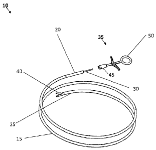
[0050] FIG. IA shows one embodiment of a forceps system 10 that may be used in
one or
more of the methods disclosed below. The forceps system 10 includes a flexible
body 15 with
a proximal end 20 and a distal end 25. The flexible body 15 may be sized to
fit within a tool
channel or lumen of an endoscope. The flexible body 15 may also include other
lumens, such
as a guide wire lumen to allow tracking to a specific site over a guide wire.
The guide wire
lumen may also be used to direct the tool to a surgical site without the use
of an endoscope. An
actuator 30 extends through the body 15 and is removeably coupleable to a
handle 35 near the
proximal end 20 and an actuatable jaw 40 near the distal end 25. The
actuatable jaw 40 may be
a pair of opposed jaws, and depending on their configuration, the forceps
system may be biopsy
forceps, grasping forceps, and hemostatic forceps. In some embodiment, the
actuatable jaw 40
may be removed and replaced by other actuatable tools, such as snares, magnet
tool, biopsy
cup, hook, or other suitable tools.
[0051] The handle 35 includes an attachment portion 45 and a forceps actuator
50. The
attachment portion 45 is removeably coupled to the distal end 20 of the body
with, for example,
a set screw through the attachment portion 45 engaging the distal end 20. The
forceps actuator
50 is operatively engageable to the actuator 30. In one embodiment, the
actuator 30 has screw
threads on the end and the forceps actuator 50 engages the threads. When
operatively engaged,
the forceps actuator 50 is configured to control the actuatable jaws by moving
the actuator in
and out. In addition, the forceps actuator 50 may also be configured to rotate
the actuatable jaw
40 up to 360 degrees by rotating the actuator 30. A pull wire (not shown) may
also be included
to articulate the distal end 25 of the body along with the actuatable jaw 40.
In use, when the
forceps system 10 is within a tool channel of an endoscope and the handle 35
is uncoupled
from the body 15, the endoscope can be withdrawn without removing the forceps
system10.
The forceps jaw 40 may be locked with a forceps lock prior to removal of the
handle. The
forceps lock may be a set screw through the body 15 that engages and locks the
actuator 30 in
place. Locking the actuator 30 may also lock the actuatable jaw 40 in a fixed
position. The
7
CA 02751851 2011-08-08
WO 2010/093951 PCT/US2010/024135
forceps lock may also serve the purpose of an RF connection to the actuatable
jaw (and other
actuatable tools).
[0052] FIG. 1B shows an alternative embodiment for the actuatable jaw 40. In
this
embodiment, the actuatable jaw comprises one or more microblades 55 to create
precise
incisions in both endoscopic and NOTES surgery. The attached microblades allow
better
control over the size of the incision and thus permit easier fitting of
correspondingly-sized
balloon closure devices. The micro blades are mechanically limited and can
help prevent
uncontrolled incisions that other types of cutting devices may not, such as an
RF needle knife.
[0053] The body 15 is made of a flexible and low friction material, such as
PTFE, stainless
coil, or a combination of both. The body 15 and actuatable jaw 40 (and other
actuatable tools)
are sized to be compatible with a 2.8 mm tool channel on an endoscope. The
length of the
forceps may be between 1 and 3 meters.
[0054] In many of the embodiments, the forceps system 10 may be used for
general
peritoneal exploration and tissue resection using NOTES approach with a
flexible endoscope to
perform a procedure, as will be described in more detail below. The endoscope
may also
include steering mechanisms that are used to steer the distal portion of the
endoscope. The
endoscope may include one or more tool channels that extend through the
endoscope and
provide an opening through which surgical instruments, such as the forceps
system 10, may be
inserted.
[0055] In one embodiment, a method of using a forceps system 10 includes
advancing an
endoscope into an internal surgical site, advancing jaws 40 and a first end
25of an elongate
flexible body 10 of the forceps system through a tool channel of the endoscope
into the site,
grasping a tissue with the forceps, removing a proximal handle 35 from a
second end 20 of the
elongate body 15 of the forceps, retracting the endoscope out of the site over
the elongate body
while the forceps grasps the tissue, and replacing the handle 35 on the
forceps while the forceps
grasps the tissue.
[0056] Other instruments may also be advanced through the endoscope tool
channel, such as
an RF catheter, to create a port or transgastric tract from the stomach into
the peritoneal cavity.
The flexible endoscope may be of the type that is typically used by
gastroenterologists in
8
CA 02751851 2011-08-08
WO 2010/093951
PCT/US2010/024135
treating the upper gastrointestinal tract and in accessing the esophagus or
stomach. The
endoscope allows the physician to visualize while performing procedures. The
flexible
endoscope may use fiber optics or a charge coupled device (CCD) mounted at the
distal end of
the endoscope to generate images.
[0057] During procedures through the mouth, the patient may be given a numbing
agent that
helps to prevent gagging. The endoscope is then passed through the mouth, into
the stomach
and through the port into the peritoneal cavity.
[0058] The endoscope may be used in locating a desired tissue site in the
stomach. A
transgastric tract is created through the stomach wall at the desired tissue
site. The transgastric
tract may be made using a RF catheter, RF guide wire, an endoneedle, or other
suitable
instrument. The size of the transgastric tract depends on the size of the
device to go through,
and have a diameter from 0.014" to 0.250".
[0059] The method disclosed below is directed toward Natural Orifice
Translumenal
Endoscopic Surgery (NOTES) from within the stomach into the peritoneal cavity.
In one
example, the resection and removal of the appendix using NOTES. In another
example, the
removal of a gallbladder using NOTES. The disclosed methods are shown as
examples, as
other combinations of devices may be combined to accomplish the same outcome.
Example 1 ¨ Resection of Appendix Using NOTES
[0060] Figs. 2A-2D show one embodiment using Natural Orifice Translumenal
Endoscopic
Surgery (NOTES) through the stomach to remove an appendix. Some of the
equipment that
may be used in this embodiment includes an endoscope, RF catheter, guide wire,
forceps with
removable handle, fluoroscope, endoscopic snare with electrocautery
connection,
electrocautery machine coupled to the snare, endoscopic grasper and closure
devices.
[0061] One embodiment of the method includes the following steps:
1. Placing an endoscope 100 into the mouth 105 of a patient 110 until it is
inside the
stomach lumen 115.
2. Locating and creating a first transgastric tract or port 120 with a RF-
Balloon
Translumenal Crossing Device and RF guide wire. Dilating the balloon to
maximum
9
CA 02751851 2011-08-08
WO 2010/093951 PCT/US2010/024135
pressure for at least 30 seconds and then crossing into the peritoneal cavity.
Removing
the RF guide wire and replacing with a 0.035" guide wire across the stomach
wall.
3. Pushing the endoscope 100 through the first transgastric tract 120 into the
peritoneal
cavity to an internal surgical site, in this case the appendix 125.
4. Inspecting the peritoneum to verify appendicitis using the endoscope 100.
5. Removing the RF-Balloon Translumenal Crossing Device and tracking a forceps
system
130 with removable handle 135 over the guide wire and grasping the appendix
125 with
actuatable jaw 140 at the base near the colon. Locking the actuatable jaw 140
of
forceps system 130, removing the handle 135 from the forceps and retracting
the
endoscope 100 out of the mouth, leaving the forceps system 130 in place.
Replacing
the handle 135 on to the forceps system 130 (Fig. 2C).
6. Replacing the endoscope 100 back into the lumen of the stomach and
determining a
second site such that it facilitates resection of the appendix. Dilating a
second
transgastric tract or port 145 using the RF-Balloon Translumenal Crossing
Device on
the stomach wall.
7. Placing endoclips around the base of the appendix to seal prior to
resection.
8. Placing an endoscopic snare with electrocautery connection 150 through the
endoscope
tool channel and around the appendix 125. Begin resection using an
electrocautery
machine coupled to the snare. The actuatable jaw 140 of forceps system 130 may
be
manipulated to assist in placing the snare around the appendix.
9. Placing an endoscopic grasper in a second endoscope tool channel and
grasping the
appendix prior to completing the resection. Removing the appendix through the
second
transgastric tract or port created for the endoscope. The removal of the
appendix may
be done while removing the endoscope.
10. Inspecting for bleeding and leaks.
11. Closing the two transgastric tracts 120, 145 using appropriate means.
Example 2 ¨ Endoscopic Gallbladder Removal Using NOTES
[0062] One embodiment of the method includes the following steps:
CA 02751851 2011-08-08
WO 2010/093951 PCT/US2010/024135
1. Place an endoscope into the stomach and dilate a tract using the RF-Balloon
Translumenal Crossing Device at an appropriate location on the stomach wall.
Remove
the RF wire from the balloon and place a guide wire across the dilated site.
2. After dilating, cross into the peritoneal cavity with the endoscope.
3. Inspect the peritoneum and verify the location of the gallbladder. Remove
the balloon
and track the handleless grasper with the right angle clamp tip over the wire
and clamp
the cystic duct.
4. Remove the handle from the endoscopic clamp tool and remove the endoscope.
Reattach the handle.
5. Place the endoscope back into the lumen of the stomach and determine a
working port
for the endoscope such that it facilitates resection and removal of the
gallbladder.
Dilate a large tract using the RF-Balloon Translumenal Crossing Device and
place a
guide wire across the transgastric tract. Remove the balloon crossing device.
6. Attach endoclips to the cystic duct away from the common bile duct.
7. Place grasper through the endoscope. Using the grasper to manipulate the
cystic duct,
apply RF energy to the endoscopic clamp tool placed initially and dissect the
cystic
duct.
8. Release the endoscopic clamp tool and use the grasper tool in the endoscope
to direct
the clamp tool around the cystic artery. Remove the grasper.
9. Using a similar technique place endoscopic clips around the cystic artery.
10. Once the clips are attached replace the endoscopic grasper into the tool
channel to
manipulate and resects the cystic artery by applying RF energy to the
endoscopic clamp.
11. Place an endoscopic RF tool with hook tip into the tool channel and
dissect the
gallbladder off the liver bed.
12. Remove the gallbladder carefully through the working port.
13. Close the initial transgastric site and the working port using appropriate
means.
[0063] FIGs. 3A-3B show one embodiment of a closure device 200 compatible for
use with
natural orifice translumenal endoscopic surgery (NOTES) to close a
transgastric tract or port
once the surgery or procedure is complete. The closure device 200 includes a
catheter 205 with
a flexible body 210 having an inflation lumen 215. A balloon 220 is removeably
coupled to the
distal end of the catheter 205, the balloon 220 having a valve 225 in fluid
communication with
11
CA 02751851 2011-08-08
WO 2010/093951 PCT/US2010/024135
the inflation lumen 215. An inflation device 230 is in fluid communication
with the inflation
lumen 215 to inflate the balloon 220. The valve 225 may be designed to close
and seal once it
is disconnected from the inflation lumen 215. The catheter 205 and balloon 220
may have an
antibiotic coating. The balloon 220 may be made from a compliant material,
such as silicon or
polyurethane. The closure device 200 may be sized to fit within a tool channel
of an endoscope
for delivery of the balloon to the tract or port. As shown in Fig. 3B, once in
place across the
transgastric tract, balloon 220 is inflated to close the tract 250; the
catheter 205 is then
uncoupled and removed, leaving the inflated balloon 220 in place.
[0064] In one embodiment shown in FIG. 4, balloon 220 may be used as a
temporary closure
device to close a transgastric tract or port 250 created in the mucosa 255 and
stomach wall 260
between the stomach 265 and peritoneum 270. The balloon 220 is delivered to
the tract 250 on
catheter 205. The delivery may be done through a tool channel of an endoscope.
As the
mucosa 255 and stomach wall 260 healing progresses, the fibers tighten and
tract opening
becomes smaller, and the balloon 220 changes shape (dotted lines). Once the
healing is
complete, the balloon 220 may be deflated and removed.
[0065] FIGs. 5A, 5B, 5C, and 5D show embodiments of a double balloon closure
device 300
having a peritoneal side balloon 305 and a gastric lumen side balloon 310
joined by a narrow
inflatable portion 315. The balloon closure device 300 is sized to close a
transgastric tract or
port, such as tract 250 discussed above. The narrow inflatable portion 315 may
have a diameter
between 5mm to 50mm and a length between lmm and 24mm. The narrow inflatable
portion
315 may be shaped to follow the general shape of the incision; thus the cross
sectional shape of
the narrow portion 315 may be circular, as shown in FIG. 5D or ovoid (or
otherwise elongate)
as shown in FIG. 5C. The diameters of balloons 305 and 310 are greater than
the diameter of
the narrow inflatable portion 315. Device 300 also includes an inflation valve
320 for inflating
the balloons. The inflation valve may have dual self-sealing rings separated
by an adhesive
chamber. The components of the closure device 300, such as the valve 320
and/or body
portions 305, 310, 315, may be biodegradable to allow timed deflation.
[0066] FIGs. 6A, 6B, 6C and 6D show embodiments of a balloon closure device
400 having
a peritoneal side balloon 405 and a gastric lumen side disk 410 joined by a
narrow inflatable
portion 415 coupled to an inflation valve 420 for inflating the balloons. The
balloon closure
12
CA 02751851 2011-08-08
WO 2010/093951
PCT/US2010/024135
device 400 is sized to close a transgastric tract or port, such as tract 250
discussed above. The
narrow inflatable portion 415 may have a diameter between 5m to 50mm and a
length between
lmm and 24mm. The narrow inflatable portion 415 may be shaped to follow the
general shape
of the incision; thus the cross sectional shape of the narrow portion 315 may
be circular, as
shown in FIG. 6D or ovoid (or otherwise elongate) as shown in FIG. 6C. The
diameter of
balloon 405 and/or disk 410 is greater than the diameter of the narrow
inflatable portion 415.
The inflation valve may have dual self-sealing rings separated by an adhesive
chamber. The
components of the closure device 400, such as the valve 420 and/or body
portions 405, 410,
415, may be biodegradable to allow timed deflation.
[0067] In some embodiments, the single balloon or dual balloon closure devices
may contain
one or more structures to dispense medication, bio glue or fibrin type sealant
to promote or
accelerate healing. FIG. 6E shows a dual balloon closure 428 with a structure
430 that delivers
medication, bio glue or fibrin type sealant, or biomaterial plug. Structure
430 communicates
with the delivery catheter through a lumen of the structure that connects the
valve on the
balloon to the proximal port on the delivery catheter. Medication (for
example, antibiotics or
other types of medication that increase the healing process), bio glue or
fibrin type sealant may
be injected into the structure through the proximal port to dispense sealant
around the incision
and over the balloon in the peritoneal cavity.
[0068] As shown in FIG. 6F for a single balloon closure device , in other
alternative
embodiments, the single balloon or dual balloon closure devices 435 may
comprise concentric
balloons on the peritoneal side. The inner balloon 440 may communicate through
a lumen 470
with an inflation port 460 to form an anchor on the peritoneal side. The outer
balloon 450 may
be perforated and comprise a second channel in communication with the delivery
catheter to
dispense medicine, bio glue or sealant through the perforations so as to fill
some or all of the
remaining gaps in between the closure device and the incision site through the
stomach wall
and to effectively seal and/or cover up the incision site.
[0069] As shown in FIG. 6G for a single balloon closing device, in other
alternative
embodiments, the single or double balloon closure devices on the peritoneal
side comprise
anchoring balloons that are perforated 430. The perforated balloons desirably
contain a type of
biocompatible sealant, capable of solidification within a short amount of
time. Thus, a
13
CA 02751851 2011-08-08
WO 2010/093951 PCT/US2010/024135
biocompatible type of sealant, such as fibrin, may be both be dispersed over
the incision site
and used to keep the anchor inflated on the peritoneal side once it
solidifies.
[0070] FIG. 7 shows one embodiment of a closure device catheter 500 for use
with the
balloon closure devices. The catheter 500 includes a flexible shaft 505 having
a proximal end
510 and a distal end 515. The shaft 505 may be compatible with a gastric
endoscopic tool
channel. An inflation lumen 520 extends through the shaft 505 and is coupled
to an inflation
port 525 on the proximal end. The distal end 515 is configured to engage a
valve of the balloon
to inflate it. In some embodiments, the distal end 515 is configured to pierce
through a closure
balloon device to inflate the balloon and then seal the piercing using an
optional adhesive
dispensing lumen 530 coupled to an adhesive lumen port 535. The catheter 500
may also have
a guide wire port 540 and guide wire lumen 545 for tracking the catheter 500
over a guide wire.
[0071] FIG. 8A shows one embodiment of a Balloon Translumenal Crossing Device
600
having a balloon 605 on a distal end for creating and dilating a transgastric
cut 610 in a
stomach wall 615 made by a fixed needle 620 at the tip of the catheter body
630 to facilitate
initial incision prior to dilation. It is to be noted that Balloon
Translumenal Crossing Device
600 may optionally be equipped with a removable RF wire 622 or an
electrocautery blade (not
shown) within a guide wire lumen 625 incorporated within the catheter body 630
for the
purpose of creating and dilating a trasngastric cut 610. As shown in FIG 8B,
the balloon 605
may be inflated with enough pressure to dilate the transgastric cut 610
opening in the stomach
wall 615, creating a working port or transgastric tract. In other embodiments,
the balloon 605
may be inflated to create space within the peritoneal cavity 635. The balloon
605 may be
formed of either a compliant or non-compliant material such as, e.g.,
polyurethane,
polyethylene, polyester or a rubber material such as silicone, depending on
the use of the
catheter. Once the RF wire 622, needle 620, or electrocautery blade is
removed, the lumen
625 may be used to place a guide wire across the transgastric cut 610. A
handle 640 on the
proximal end of the catheter 600 may also removable to allow removal of an
endoscope
without removing the catheter. The catheter 600 may also serve as a guide rail
for an
endoscope or any other tool with an appropriate lumen. As shown in Fig. 8C,
the balloon may
comprise microblades 605 that cut stomach muscle tissue and thus minimize the
tearing of the
muscle tissue.
14
CA 02751851 2011-08-08
WO 2010/093951 PCT/US2010/024135
[0072] FIG. 9A shows an embodiment of a Mechanical Translumenal Crossing
Device 700
having deployable dilator arms that dilate the transgastric cut 710 opening in
the stomach wall.
A spring-loaded laparoscopical surgery knife 710 or other tissue penetrating
structure is
released by a trigger 720 located on the handle 730. Once the initial cut or
opening is formed
or finished, and a distal end of the crossing device is advanced into the
initial opening, a
plunger 740 is used to deploy the dilator arms 750 to dilate the transgastric
cut. FIG. 9B shows
the Mechanical Translumenal Crossing Device with its dilator arms deployed.
Advantageously, the elongate bodies or catheters of the tissue penetrating and
dilating
structures may be sufficiently flexible for transgastric (and other NOTES)
procedures.
[0073] Although the foregoing invention has been described in some detail by
way of
illustration and example, for purposes of clarity of understanding, it will be
obvious that
various alternatives, modifications and equivalents may be used and the above
description
should not be taken as limiting in scope of the invention which is defined by
the appended
claims.