Note: Descriptions are shown in the official language in which they were submitted.
CA 02751949 2011-09-12
JCO5006EPEPT
CARTON WITH OPENING
FOR DISPLAYING PRODUCT
FIELD OF THE INVENTION
[0001] The present invention relates to secondary packaging for a primary
package or
container or other type of article. More particularly, the present invention
relates to a
secondary packaging with a window not only through which the primary packaging
or
container or other type of article is visible but also through which a portion
of the primary
packaging or container or other type of article projects. Even more
particularly, the present
invention relates to a secondary packaging with a window and additional
support structure
for the primary package or container or other type of article, the support
structure being
formed integrally with and as an extension of the wall panels of the secondary
packaging.
BACKGROUND OF THE INVENTION
[0002] Many variants of cardboard or plastic boxes for a primary package (the
package
that directly contains the product being sold, such as a cream, lotion,
cosmetic, shampoo, or
therapeutic or skin care product) or container or other type of article
(hereinafter "product"
for the sake of simplicity without intent to limit) have been proposed,
capable of holding the
product therein in position for efficient storage and presentation at a retail
location. Of such
boxes, there also are many variants which include open windows through which
the product
is visible, and may even project, for an added visual effect. Such windowed
boxes either
support the product on the bottom wall of the box, or may support the product
in a raised
position. Raising of the product not only results in a unique visual effect,
but also provides
additional surface area on the front of the box (e.g., not only above and
along the sides, but
also below the window) for providing information or other indicia (e.g.,
branding) related to
the product.
[0003] One particular variant of a windowed box is described in European
patent EP
1 502 862, incorporated herein in its entirety by reference as if fully
disclosed herein (and
sharing a common inventor with the present invention), in which a box is
provided with
windows on the front wall as well as the right and left sides thereof. The
inventive box has
right and left side walls formed to have bellows or gussets which themselves
form strips
that extend inwardly into the box to provide a support for the tub or pot to
be held within
and displayed by the box. A panel or flap formed from the front wall is folded
inwardly to
rest on the strips formed by the left and right side walls. The tub or pot is
supported on the
flap and may be affixed to the flap and thereby stabilized against undesired
movement.
1
CA 02751949 2011-09-12
JCO5006EPEPT
Thus, the main surface (typically front) of the tub or pot, which bears the
information or
markings (hereinafter "indicia" for the sake of convenience without intent to
limit) that the
manufacturer desires to be always presented for viewing by the consumer, may
be
maintained in an appropriate position for viewing by the consumer through the
front
window of the box. The tub or pot thereby is held in a raised position,
projects somewhat
from the box, and is maintained in a desired orientation so that indicia
thereon are
maintained in position for ready viewing by consumers. The gusseting of the
left and right
side walls of the box in combination with the windows in the left and right
side walls result
in a portion of the tub or pot projecting through the windows of the left and
right side walls
in addition to the window in the front wall.
[0004] It will be appreciated that the above-described box is particularly
suitable for a
tub or pot having a great enough diameter such that sufficient box material
remains to
support the tub or pot despite the windows in the right and left side walls as
well as in the
front wall. It would be desirable to form a box that is narrower than the
prior art box and
thus which does not have windows in the right and left side walls, yet which
provides such
benefits of raising the product therein for viewing, allowing at least a
portion of the product
to project through a window in the box, and maintaining the product in a
desired orientation
for consumer viewing of indicia on the product.
SUMMARY OF THE INVENTION
[0005] In accordance with the principles of the present invention, a box
configured to
contain and to display a product is provided with a window through which a
portion of the
product projects for enhanced display and viewing. In addition, the product is
supported in
a raised position in the box, and support structures are formed to project
from the side walls
of the box to provide upper and lower supports for the product to restrain the
product from
axial movement in the box. Preferably, the box is formed from a single blank
such that
additional inserts for stabilizing the product within the box are not needed
and not provided.
[0006] Additional features may be provided to further stabilize the product
from
movement within the box. For instance, a flap may be provided for fixing the
product in
place relative to the box. Additional flaps or fins may be provided to
stabilize the product
within the window and / or to reinforce the box strength along the window.
Bellows in the
side walls may be formed to stabilize the product against lateral shifting
within the box.
2
CA 02751949 2011-09-12
JCO5006EPEPT
[0007] These and other features and advantages of the present invention will
be readily
apparent from the following detailed description of the invention, the scope
of the invention
being set out in the appended claims.
BRIEF DESCRIPTION OF THE DRAWINGS
[0008] The detailed description will be better understood in conjunction with
the
accompanying drawings, wherein like reference characters represent like
elements, as
follows:
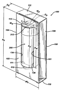
[0009] FIGURE 1 is a perspective view of an exemplary box formed in accordance
with
principles of the present invention with a product held therein and displayed
through the
window thereof;
[0010] FIGURE 2 is an enlarged view of an exemplary support structure formed
in
accordance with principles of the present invention and illustrated in
isolation with bottom
of a product to be supported thereby shown in phantom;
[0011] FIGURE 3 is an exemplary blank from which a box in accordance with
principles of the present invention may be formed;
[0012] FIGURE 4 is a second exemplary blank from which a box in accordance
with
principles of the present invention may be formed;
[0013] FIGURE 5 is a perspective view showing a preliminary step in assembling
the
blank of FIGURE 3 into a box in accordance with principles of the present
invention;
[0014] FIGURE 6 is a perspective view showing another step in assembling the
blank
of FIGURE 3 into a box in accordance with principles of the present invention;
and
[0015] FIGURE 7 is a perspective view showing a further step in assembling the
blank
of FIGURE 3 into a box in accordance with principles of the present invention.
DETAILED DESCRIPTION OF THE INVENTION
[0016] An exemplary box 100 formed in accordance with principles of the
present
invention is illustrated in FIGURE 1 with product 200 displayed in and
projecting at least in
part through an opening or window 101 within at least one wall of box 100. In
the
exemplary embodiments of FIGURES 1-7, window 101 is formed in only one wall,
the
front wall 102, of box 100. It will be appreciated that an additional window
may be
provided in any or all of left side wall 104, right side wall 106, or back
wall 108 of box 100.
However, in accordance with one aspect of the present invention, box 100 is
formed to
3
CA 02751949 2011-09-12
JCO5006EPEPT
contain and to display a relatively narrow product 200 and therefore the
structural integrity
of box 100 may be compromised if more than one window is provided.
[0017] Box 100 is formed in accordance with principles of the present
invention to
provide stability to product 200, particularly in the case product 200
projects at least
somewhat outside box 100 through window 101, and even more particularly when
product 200 is displayed elevated above bottom wall 110. Box 100 furthermore
may be
designed in accordance with principles of the present invention to provide
stability to
product 200 in the case product 200 is positioned within box 100 spaced below,
and thus
not abutting and stabilized by, top wall 112. Such stabilizing features will
now be
described in conjunction with the exemplary embodiment illustrated in FIGURES
1-4. In
accordance with one aspect of the present invention, box 100 is formed from a
single piece
of material (e.g., cardboard, paperboard, or the like) shaped and configured
and provided
with grooves, cut-outs, preliminary cut-outs, fold lines, and lines of
weaknesses
(perforations or nicks or score lines) and the like so that no additional
separate material or
element is necessary to provide the stabilizing functionality desired of the
inventive box.
Exemplary blanks from which such box may be formed are illustrated in FIGURES
3 and 4,
which will be described in further detail below. It will be appreciated that
features of box
blank 300 of FIGURE 3 forming elements of exemplary box 100 are designated
with the
same reference numbers increased by 200 and redundant description is omitted.
Similarly,
features of box blank 400 of FIGURE 4 forming elements of a box formed in
accordance
with principles of the present invention are designated with the same
reference numbers as
the features of box blank 300 increased by 100 and redundant description is
omitted.
[0018] Referring now to FIGURE 1, exemplary box 100 is illustrated in an
assembled
closed configuration with product 200 therein extending in part through window
101. The
overall external shape of box 100 is in the form of a parallelepiped with a
height Hb greater
than width Wb or depth Db such that box 100 is generally considered a tall and
narrow box
for a tall and narrow product such as a canister-like container (e.g., a
cylindrical bottle).
For instance, the proportions of box 100 preferably are such that height Hb is
at least about
2 times and more preferably 2.5 times greater than width Wb or depth Db. As
such, box 100
has preferably only one window, as additional windows cannot readily be
accommodated
given the relative width Wb or depth Db of box 100. The wall in which window
101 is
provided (in the exemplary embodiment of FIGURES 1-7, front wall 102)
preferably is
substantially planar. In addition, window 101 preferably is positioned spaced
apart from
the edges of the wall in which window 101 is formed so that the material of
such wall
4
CA 02751949 2011-09-12
JCO5006EPEPT
borders all sides of window 101 (e.g., to permit indicia to be provided on the
wall in which
window 101 is formed surrounding all sides of window 101). However, other
configurations are well within the scope of the present invention. Also as
noted above, it
will be appreciated that window 101 preferably is spaced from bottom wall 110
so that a
product displayed therein is elevated above bottom wall 110. Window 101 has a
height HH,
selected to substantially equal the height Hp of product 200 to be displayed
therein and to
project therethrough. Window 101 has a width WH, selected to be less than
width Wp of
product 200 to be displayed therein so that product 200 may project only
partially
therethrough but is prevented from completely passing through window 101
because of the
differences in widths between window 101 and product 200. As may be
appreciated, such
dimensions of window 101 contribute to stabilization of product 200 within box
100 by
virtue of the tight fit of product 200 therein, in the axial direction (along
height Hp) as well
as the lateral direction (along width Wp).
[0019] Product 200 is further stabilized within box 100 by virtue of depth Db
of box 100
being selected to substantially equal depth Dp of product 200. Such
stabilization by virtue
of the dimensions of box 100 relative to the dimensions of product 200 is
further enhanced
by the provision of uniquely formed side walls 104, 106. In particular, as in
EP 1 502 862,
side walls 104, 106 preferably are pulled inwardly to have a bellow or gusset
configuration.
More particularly, side walls 104, 106 preferably each include a vertical fold
line 105, 107,
respectively, along which side walls 104, 106 are folded inwardly so that a
central region of
each of side walls 104, 106 projects inwardly into box 100 towards product
200.
Preferably, the inner surface of the inwardly directed central regions of each
of side
walls 104, 106 abuts a side of product 200 so that the bellowed or gusseted
side walls 104,
106 together provide lateral stabilization to product 200. The formation of
side walls 104,
106 to be bellowed or gusseted not only provides lateral stability, but also
reduces depth Db
of box 100 to be less than depth Dp of product 200 so that product 200
projects at least
somewhat outside of box 100 through window 101. As may be appreciated, side
walls 104,
106 present, initially, a box that readily receives the full width Wp and
depth Dp of
product 200, yet may be folded inwardly to the gusseted or bellowed
configuration to
present a smaller box depth Db and to cause object 200 to project through
window 101.
[0020] In contrast with EP 1 502 862, as noted above, side walls 104, 106 of
box 100 of
the present invention preferably do not have windows therein. As such, side
walls 104, 106
do not provide upper and lower strips as in EP 1 502 862 to provide support to
the bottom
and top of product 200. Instead, as may be seen with reference to FIGURE 2, an
extension,
5
CA 02751949 2011-09-12
JCO5006EPEPT
such as in the form of a tab, is formed in at least one, and preferably both
(as may be
appreciated with reference to FIGURES 3 and 5-7, of side walls 104, 106 to
provide upper
and / or lower support to product 200. Preferably, at least one upper
extension and at least
one lower extension extends from at least one, and preferably both, of side
walls 104, 106.
In the embodiment of FIGURES 1-7, the upper and lower supports preferably are
formed as
extensions of the panels forming box 100. As such, no additional material is
needed to
support product 200 within box 100 and assembly of box 100 is simplified
(since an extra
step of inserting a support element is unnecessary).
[0021] Exemplary box 100 preferably is formed from a single blank, such as
exemplary
box blank 300 illustrated in FIGURE 3 or exemplary box blank 400 illustrated
in
FIGURE 4. Box blanks 300 and 400 are single monolithic blanks with a series of
panels
separated along fold lines about which the panels may be folded to form box
100.
Exemplary box blank 300 is illustrated in FIGURE 3 as including at least left
side wall
panel 304 (preferably formed by two portions 304a, 304b coupled along fold
line 305, along
which left side wall panel 304 is folded to form the above-described gusseted
or bellowed
configuration), front wall panel 302, right side wall panel 306 (preferably
formed by two
portions 306a, 306b coupled along fold line 307, along which right side wall
panel 306 is
folded to form the above-described gusseted or bellowed configuration), back
wall
panel 308, and left side wall interior panel 309, consecutively arranged and
laterally
integrally interconnected with one another along vertical fold lines. Panels
304, 302, 306,
309, and 305 are folded along their respective fold lines to form left side
wall 104 (upon
overlapping of panels 304 and 309, which may optionally be secured with a
strip 303 of
adhesive or the like), front wall 102, right side wall 106, and back wall 108
of box 100.
Support extensions of exemplary box 100 are formed as cut-outs from one of
side
walls 104, 106 and extensions from the other of side walls 104, 106. More
particularly,
with reference to the exemplary embodiment of FIGURES 2 and 5-7, left side
wall 104 is
formed from a left side wall panel 304 of box blank 300 overlapped with (and
over) left side
wall interior panel 309. As such, bottom left support extension 114 is formed
from an
extension 314 of left side wall interior panel 309 (specifically, an extension
along the free
vertical edge of left side wall interior panel 309), such as in the form of a
tab. Bottom left
support extension 114 preferably has a height substantially equal to the
distance of bottom
edge 111 of window 101 from bottom wall 110 of box 100 to reach and provide
support to
bottom 210 of product 200. Right side wall 106 is formed from right side wall
panel 306,
which is surrounded by wall panels 302, 308 that respectively form front wall
102 and back
wall 108. As such, right side wall 106 does not present a free edge from which
a support
6
CA 02751949 2011-09-12
JCO5006EPEPT
extension may be formed. Instead, bottom right support extension 116 is formed
from a
cut-out in right side wall panel 306 positioned and configured to form an
extension, such as
in the form of a tab, which projects inwardly into box 100 to provide support
to
product 200, as illustrated in FIGURE 2. Bottom right support extension 116
preferably has
a height substantially equal to the distance of the bottom edge 111 of window
101 from
bottom wall 110 of box 100 and thus the height of bottom left support
extension 114,
thereby reaching and providing support to bottom 210 of product 200
(illustrated in
phantom in FIGURE 2) positioned in and extending partially out of window 101.
It will be
appreciated that bottom right support extension 116 preferably extends from
right side wall
panel portion 306b at an angle with respect to right side wall panel portion
306a. Bottom
left side support extension 114 similarly extends at an angle with respect to
left side wall
panel portion 304b. In combination, bottom left support extension 114 and
bottom right
support extension 116 support the bottom 210 of product 200 so that product
200 may be at
the proper height to project at least in part through window 101.
[0022] Top support extensions may be provided in box 100 in a manner similar
to the
manner in which lower support extensions are provided. Top left support
extension 124
preferably is formed from an extension 324 of left side wall interior panel
309 (specifically,
an extension along the free vertical edge of left side wall interior panel
309), such as in the
form of a tab, having a height substantially equal to the distance of the top
edge 113 of
window 101 from top wall 112 of box 100, thereby reaching and providing
support to
top 212 of product 200. And, top right support extension 126 is formed from a
cut-out in
right side wall panel 306 positioned and configured to form an extension, such
as in the
form of a tab, having a height substantially equal to the distance of the top
edge 113 of
window 101 from top wall 112 of box 100 and thus the height of top left
support
extension 124, thereby reaching and providing support to top 212 of product
200.
Preferably, top right support extension 126 extends at an angle with respect
to right side
wall 106. In combination, top left support extension 124 and top right support
extension 126 support top 212 of product 200 so that product 200 may be at the
proper
height to project at least in part through window 101.
[0023] It will thus be appreciated that support extensions 114, 116, 124, and
126
contribute to stabilization of product 200 within box 100 without requiring a
secondary
support structure to be inserted within box 100. Moreover, support extensions
114, 116,
124, and 126 are readily formed in box blank 300 and readily assembled during
assembly of
box blank 300 into box 100 (as described in further detail below) to provide
the desired
7
CA 02751949 2011-09-12
JC05006EPEPT
support to product 200 without requiring complex assembly steps. Exemplary box
blank 400 illustrated in FIGURE 4 has similar panels and other features as
provided in
exemplary box blank 300 of FIGURE 3 providing substantially similar functions.
Accordingly, a detailed description of exemplary box blank 400 is omitted,
reference being
made to the description of exemplary box blank 300 as applicable to exemplary
box
blank 400.
[0024] Box 100 formed in accordance with principles of the present invention
may be
provided with additional features to enhance and / or to increase stiffness
and structural
stability of box 100. Such features preferably also contribute to the ability
of box 100 to
maintain its structural integrity (i.e., resistance to being crushed or
damaged or otherwise
altered in a manner that affects the appearance of box 100) during packing,
shipping, and
handling, as well as maintaining an undamaged appearance on shelf.
[0025] In accordance with one aspect of the present invention, as described
above,
box 100 and product 200 are selected so that at least a portion of product 200
projects
outwardly from box 100 through window 101. As such, the portion of front wall
102 below
bottom edge 111 of window 101 may be susceptible to tearing upon axial
movement or
jolting of product 200 against window 101. In accordance with one embodiment
of the
present invention, a bottom reinforcing flap 140 is formed along front wall
102 (see
FIGURES 5-7) from blank flap 340 folded in along bottom edge 111 of window 101
and
against the interior surface of front wall 102. Preferably, bottom reinforcing
flap 140 is
adhered or otherwise secured to the interior surface of front wall 102. As
such, bottom
reinforcing flap 140 in conjunction with the lower portion of front wall 102
below
window 101 create a double-wall area that reinforces window 101 against forces
generating
by supporting product 200.
[0026] In accordance with a separate and independent feature of the present
invention,
an top support flap 142 may be formed along front wall 102 (see FIGURES 5-7)
from blank
flap 342 folded along top edge 113 of window 101. Top support flap 142 may
function to
stabilize product 200 within box 100, such as against upward movement or
against rotation.
As such, top support flap 142 may provide the functions provided by the lower
flap 24 of
EP 1 502 862. If desired, a glue dot 143 advantageously may be utilized to
secure
product 200 to top support flap 142 thereby securing product 200 against
rotation relative to
box 100. Undesired or accidental rotation of product 200 relative to box 100,
which would
have the undesired effect of concealing markings on product 200 intended for
ready
8
CA 02751949 2011-09-12
JCO5006EPEPT
viewing by consumers, is thus substantially prevented in a particularly
reliable and
inexpensive and simple manner.
[0027] A combination of the above-described wall reinforcement provided by
bottom
reinforcing flap 140 and product stabilization provided by top support flap
142 may be
provided by a modification to the box blank used to form box 100, such as the
modification
embodied in exemplary box blank 400 of FIGURE 4. An top reinforcing flap 442'
is
formed in blank 400 similar to blank flap 342 (forming top support flap 142),
except instead
of being folded to be substantially perpendicular to front wall 102 to provide
top support to
the top end of product 200, top reinforcing flap 442' is folded inwardly to be
secured to the
interior surface of front wall 102 to provide reinforcement to the upper
region of front
wall 102 above window 101. As such, top reinforcing flap 442' is similar in
function to
bottom reinforcing flap 140 described above (such bottom reinforcing flap
preferably
similarly being provided in box blank 400 to reinforce front wall 102 below
window 101).
Stabilization of top 212 of product 200 may be provided by an top support flap
442 similar
to top support flap 342 formed in box blank 300, except formed from back wall
panel 308
rather than from front wall panel 302. More specifically, exemplary box blank
400
provides an top support flap 442 by means of a cut-out in back wall panel 408.
Top support
flap 442 is folded inwardly into the box formed from box blank 400 similar to
the manner
in which top support flap 342 of box blank 300 is folded to provide similar
support to the
top of product 200.
[0028] An additional feature which may be provided to strengthen box 100 and /
or to
stabilize product 200 within box 100 is one or more lateral support flaps or
fins along the
sides of window 101. In the exemplary embodiment of FIGURES 1-7, left lateral
fin 144
and right lateral fin 146, respectively extend from left edge 134 and right
edge 136 of
window 101, inwardly into box 100. Lateral fins 144, 146 improve rigidity of
box 100 by
permitting distribution of lateral forces from product 200 against box 100
over at least a
portion of the surface of lateral fins 144, 146 instead of merely along edges
134, 136.
Contact of product 200 with a greater extent of material -- at least a portion
of the surface of
lateral fins 144, 146, in contrast with an edge of box material at edges 134,
136 -- provides
increased frictional forces against product 200 and thus reduction of movement
of
product 200 relative to box 100.
[0029] Another arrangement that may be provided to strengthen box 100 and / or
to
stabilize product 200 within box 100 is the presence of tabs 152, 154, 156,
158 (such as
triangular tabs as illustrated in, e.g., FIGURES 6 and 7) extending at the top
and bottom
9
CA 02751949 2011-09-12
JC05006EPEPT
ends of side wall panels 304, 306 to fold into box 100 with top wall panel 310
and bottom
wall panel 312. Thus, at the bottom edge of box 100, tabs 154, 158 are folded
inwardly to
lie substantially parallel to and along bottom wall 110 of box 100. Similarly,
at the top
edge of box 100, tabs 152, 156 are folded inwardly to lie substantially
parallel to and along
top wall 112 of box 100. When folded within box 100, tabs 152, 154, 156, 158
abut against
bottom wall 110 and top wall 112 and tuck-in flaps 360, 362, thereby providing
lateral
stabilization to box 100. Tabs 152, 154, 156, 158 may be dimensioned to
maintain or at
least contribute to maintaining the desired bellowed or gusseted configuration
of side
walls 104, 106. One manner of achieving such effect is by forming each of tabs
152, 154,
156, 158 as an extension from a panel portion 304a, 304b, 306a, 306b of a
respective side
wall panel 304, 306. Preferably, a single tab is formed along each side wall
104, 106 on
only one of the two portions 304a, 304b, 306a, 306b forming the bellow or
gusset
configuration so that the tab does not unduly interfere with access to product
200 within
box 100.
[0030] Yet another feature that may be provided in a box formed in accordance
with
principles of the present invention in combination or independently of the
above-described
features is an extended top tuck-in flap 360 having a length selected to
extend from top
wall 112 to top edge 132 of window 101 and thus to top 212 of product 200 to
support
product 200. In an embodiment providing an top support flap, top tuck-in flap
360 may
function to hold the top support flap in place to stabilize top 212 of product
200.
[0031] Assembly of box 100 formed of blank 300 is illustrated in FIGURES 5-7
(it
being appreciated that assembly of blank 400 into box 100 is substantially the
same as
assembly of blank 300). Briefly, left side wall interior panel 309 is folded
toward the
interior surface of back wall panel 308 of blank 300, as illustrated in FIGURE
5. Back wall
panel 308 is then folded toward front wall panel 302 and left side wall panel
portion 304a is
adhered to strip 303 on left side wall interior panel 309, thereby achieving a
flattened
configuration, as FIGURE 6, which may be shipped for further assembly at
another location
if desired. The flattened configuration may be "popped" open, as known to
those of
ordinary skill in the art, into the configuration illustrated in FIGURE 7,
causing bottom left
support extension 114, bottom right support extension 116, top left support
extension 124,
and top right support extension 126 to extend inwardly into box 100 into
position to support
a product 200 to be inserted therein. Folding of top wall panel 310 and top
tuck-in flap 360
and bottom wall panel 312 and bottom tuck-in flap 362 to form, respectively,
bottom
CA 02751949 2011-09-12
JCO5006EPEPT
wall 110 and top wall 112 of box 100 may be understood by one of ordinary
skill in the art
such that illustration of such steps is deemed unnecessary.
[0032] It will be appreciated that a box 100 formed with one or more of the
above-
described features provides and efficient and effective manner of displaying
an product 200
in a secure and stable manner through an open window 101 formed in at least
one of the
walls of box 100. Box 100 provides a consumer with a particularly clear and
direct view of
the contents of box 100, particularly specific features and / or markings on
or other details
of product 200. In addition, the consumer can readily touch product 200,
enabling a
privileged and direct contact with product 200. The configuration of a box 100
with a
window through which a portion of product 200 to be contained within box 100
projects
results in a box having a relatively small volume and outer dimensions
compared with
product 200 itself. Such compact size or outer dimensions of box 100 permits a
larger
number of such boxes to be packed in a given shipping carton or placed on a
given area on a
retail shelf. Moreover, the reduced size of box 100 requires less material and
thus is less
costly than a more conventional closed-walled box.
[0033] Thus, in accordance with the principles of the present invention, a box
is
provided with a window through which a product is displayed and may be
projected, such
box providing positional stabilization of the product with respect to the box
to inhibit and to
substantially prevent relative movement of the product with respect to the
box. In contrast
with the box disclosed in EP 1 502 862, a box formed in accordance with the
principles of
the present invention is dimensioned to correspond to a product that is not
sufficiently wide
to permit formation of windows in the side walls of the box that may
themselves provide
some support and may form support structure (in the form of strips) for the
product.
Instead, the present invention provides integrally formed support structures
that extend from
the side walls of the box without compromising the integrity of the side walls
and thus
without weakening the box structure.
[0034] It will be appreciated that the directional references "top" or "upper,
"bottom" or
"lower," "front," and "rear" or "back" do not limit the respective panels to
such orientation,
but merely serve to distinguish these panels from one another. It will also be
appreciated
that separate and independent aspects of the present invention have been
described, each, at
least alone, having unique benefits which are desirable for, yet not critical
to, the present
invention. Accordingly, the various features described herein may be used
singly or in any
combination thereof. Therefore, the present invention is not limited to only
the
embodiments specifically described herein.
11
CA 02751949 2011-09-12
JCO5006EPEPT
[0035] The exemplary embodiment illustrated in the figures has several
separate and
independent inventive features, which each, at least alone, has unique
benefits which are
desirable for, yet not critical to, the present invention. Therefore, the
various separate
features of the present invention need not all be present in order to achieve
at least some of
the desired characteristics and / or benefits of the present invention. One or
more separate
features may be combined, or only one of the various features need be present
in a box
formed in accordance with the principles of the present invention. Moreover,
throughout
the present application, reference numbers are used to indicate a generic
element or feature
of the present invention. The same reference number may be used to indicate
elements or
features that are not identical in form, shape, structure, etc, yet which
provide similar
functions or benefits. Additional reference characters (such as letters, as
opposed to
numbers) may be used to differentiate similar elements or features from one
another.
[0036] While the foregoing description and drawings represent exemplary
embodiments
of the present invention, it will be understood that various additions,
modifications and
substitutions may be made therein without departing from the spirit and scope
of the present
invention. In particular, it will be clear to those skilled in the art that
the present invention
may be embodied in other specific forms, structures, arrangements,
proportions, and with
other elements, materials, and components, without departing from the spirit
or essential
characteristics thereof. One skilled in the art will appreciate that the
invention may be used
with many modifications of structure, arrangement, proportions, materials, and
components
and otherwise, used in the practice of the invention, which are particularly
adapted to
specific environments and operative requirements without departing from the
principles of
the present invention. For example, the size or dimensions of the elements may
be varied.
The presently disclosed embodiments are therefore to be considered in all
respects as
illustrative and not restrictive, the scope of the invention being indicated
by the appended
claims, and not limited to the foregoing description.
12