Note: Descriptions are shown in the official language in which they were submitted.
CA 02752130 2011-08-10
WO 2010/093756 PCT/US2010/023841
-1-
DETECTION OF PARAMETERS IN CARDIAC OUTPUT
RELATED WAVEFORMS
BACKGROUND
[0001] Many of the parameters that can be determined from cardiac
output related waveforms, e.g., peripheral pressure waveforms, are important
not only for diagnosis of disease, but also for "real-time," i.e., continual,
monitoring of clinically significant changes in a subject. Various methods
exist
to identify and/or calculate these parameters based on analysis of various
features in cardiac output related waveforms. Few hospitals are without
equipment that employ these methods to monitor one or more cardiac output
related parameters in an effort to provide a warning that a subject's
condition is
changing.
SUMMARY
[0002] Methods for detecting parameters in cardiac output related
waveforms are described. The methods include methods for detecting
individual heart beat cycles in a cardiac output related waveform, methods for
detecting an error in an assigned starting point for an individual heart beat
cycle
in a cardiac output related waveform, methods for detecting a dichrotic notch
for an individual heart beat cycle in a cardiac output related waveform, and
methods for detecting an error in an assigned dichrotic notch for an
individual
heart beat cycle in a cardiac output related waveform.
[0003] The methods for detecting individual heart beat cycles in a
cardiac output related waveform include providing cardiac output related
waveform data and calculating a first derivative function for the waveform
data.
The order of the data for the first derivative function is then reversed in
time.
Next the amplitude of the first derivative function is compared to a threshold
value, with the threshold value being a percentage of the maximum amplitude in
13537-1 ECC-6188 PCT
CA 02752130 2011-08-10
WO 2010/093756 PCT/US2010/023841
-2-
the first derivative function. The start of a heart beat cycle is then
determined
by identifying the first time the first derivative function equals zero
immediately
after the point (i.e., prior in time) at which the amplitude of the first
derivative
function is greater than the threshold value in the reversed time order data.
The
first time the first derivative function equals zero indicates the beginning
of a
heart beat cycle.
[0004] The methods for detecting an error in an assigned staring point
for an individual heart beat cycle in a cardiac output related waveform
include
providing cardiac output related waveform data for an individual heart beat
cycle, the individual heart beat cycle having a predetermined starting point,
and
determining a maximum value of the cardiac output related waveform data.
Next a first point in the cardiac output related waveform is determined, the
first
point being the first point on the cardiac output related waveform prior to
the
maximum value that has a value equal to one-half the maximum value. The
portion of the heart beat cycle between the starting point and the first point
is
then searched for a local maximum. If a local maximum is found, the portion of
the heart beat cycle between the first point and the local maximum is searched
for a local minimum point, and the starting point for the individual heart
beat is
reassigned to the local minimum point.
[0005] The methods for detecting a dichrotic notch for an individual
heart beat cycle in a cardiac output related waveform include providing
cardiac
output related waveform data for an individual heart beat cycle, the
individual
heart beat cycle having a previously determined starting time point, and
calculating a first derivative function for the waveform data. Next a first
time
point and a second time point are determined from the first derivative
function,
the first time point being the first zero crossing after the starting time
point for
the first derivative function and the second time point being the second zero
crossing after the starting time point for the first derivative function. A
second
derivative function is also calculated for the waveform data and a third time
13537-1 ECC-6188 PCT
CA 02752130 2011-08-10
WO 2010/093756 PCT/US2010/023841
-3-
point and a fourth time point are determined from the second derivative
function, the third time point being the first zero crossing after the second
time
point for the second derivative function and the fourth time point being the
second zero crossing after the second time point for the second derivative
function. Then the portion of the second derivative function between the third
time point and the fourth time point is searched for a local maximum, the
local
maximum occurring at a fifth time point. The fifth time point corresponds to
the time point at which the dichrotic notch is located in the cardiac output
related waveform data for the individual heart beat cycle.
[0006] The methods for detecting an error in an assigned dichrotic notch
for an individual heart beat cycle in a cardiac output related waveform
include
providing cardiac output related waveform data for an individual heart beat
cycle, the individual heart beat cycle having a previously determined
dichrotic
notch time point, a previously determined starting time point, a previously
determined cardiac output maximum point, and a previously determined ending
time point, and calculating a first derivative function for the waveform data.
Then all the local maximums between the cardiac output maximum point and a
search time point in the first derivative function are determined, the search
time
point being starting time point plus two-thirds the time between the starting
time
point and the ending time point. If more than one local maximum is found, the
dichrotic notch is assigned to the time point at the second local maximum.
DESCRIPTION OF DRAWINGS
[0007] Fig. 1 shows a flow chart illustrating an example of logic for
detecting individual heart beat cycles in cardiac output related waveforms.
[0008] Fig. 2A shows an arterial pressure waveform taken over several
heart beat cycles.
[0009] Fig. 2B shows the first derivative function of the arterial pressure
waveform shown in Fig. 2A.
13537-1 ECC-6188 PCT
CA 02752130 2011-08-10
WO 2010/093756 PCT/US2010/023841
-4-
[0010] Fig. 3 shows a flow chart illustrating an example of logic for
verifying the number of individual heart beat cycles in cardiac output related
waveforms.
[0011] Figs. 4A-D show examples of cardiac output waveforms in
which arrhythmia is occurring.
[0012] Fig. 5 shows a flow chart illustrating an example of logic for
detecting an error in an assigned staring point for an individual heart beat
cycle
in a cardiac output related waveform.
[0013] Fig. 6A shows an arterial pressure waveform taken over several
heart beat cycles in which the initiation of heart beat cycles have been
incorrectly identified.
[0014] Fig. 6B shows the relevant points of a heart beat cycle for the
application of methods for detecting an error in an assigned staring point for
an
individual heart beat cycle in a cardiac output related waveform.
[0015] Fig. 7 shows a flow chart illustrating an example of logic for
detecting a dichrotic notch for an individual heart beat cycle in a cardiac
output
related waveform.
[0016] Fig. 8A shows an arterial pressure waveform taken over several
heart beat cycles.
[0017] Fig. 8B shows the first derivative function of the waveform from
Fig. 8A.
[0018] Fig. 8C shows the second derivative function of the waveform
from Fig. 8A.
[0019] Fig. 9 shows a flow chart illustrating an example of logic for
detecting an error in an assigned dichrotic notch for an individual heart beat
cycle in a cardiac output related waveform.
[0020] Fig. IOA shows an arterial pressure waveform taken over several
heart beat cycles.
[0021] Fig. I OB shows the first derivative function of the waveform
from Fig. 10A.
13537-1 ECC-6188 PCT
CA 02752130 2011-08-10
WO 2010/093756 PCT/US2010/023841
-5-
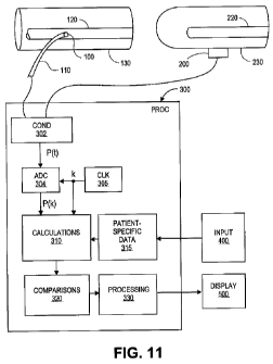
[0022] Fig. 11 is a block diagram showing the main components of a
system to implement the methods described herein.
DETAILED DESCRIPTION
[0023] Methods for detecting parameters in cardiac output related
waveforms are described. Specifically, the methods described herein include
detecting individual heart beat cycles in a cardiac output related waveform,
detecting an error in an assigned starting point for an individual heart beat
cycle
in a cardiac output related waveform, detecting a dichrotic notch for an
individual heart beat cycle in a cardiac output related waveform, and
detecting
an error in an assigned dichrotic notch for an individual heart beat cycle in
a
cardiac output related waveform. The individual heart beat cycles and the
dichrotic notch in a cardiac output related waveform, in addition to
themselves
being important parameters for a clinician, form the basis for the calculation
of
many other cardiac output related parameters, thus, the initial accurate
identification of heart beat cycles and dichrotic notch forms the basis for a
clinician to appropriately provide treatment to a subject.
[0024] As used herein, the phrase cardiac output related waveform is
used to indicate a signal related to, e.g., proportional to, derived from, or
a
function of, cardiac output. Examples of such signals include, but are not
limited to, peripheral arterial and central aortic pressure and/or flow, pulse
oxymetry waveforms, impedance plethysmography waveforms, and Doppler
waveforms. The term peripheral arterial pressure is intended to mean pressure
measured at any point in the arterial tree, e.g., radial, femoral, or
brachial, either
invasively or non-invasively. If invasive instruments are used, in particular,
catheter-mounted pressure transducers, then any artery is a possible
measurement point. Placement of non-invasive transducers will typically be
dictated by the instruments themselves, e.g., finger cuffs, upper arm pressure
cuffs, and earlobe clamps. Peripheral arterial pressure increases the further
away from the heart the measurement is taken. Regardless of the specific
13537-1 ECC-6188 PCT
CA 02752130 2011-08-10
WO 2010/093756 PCT/US2010/023841
-6-
instrument or measurement used, the data obtained will ultimately yield an
electric signal corresponding (for example, proportional) to cardiac output.
[0025] The method for detecting individual heart beat cycles in cardiac
output related waveforms as disclosed herein is shown as a flow chart in Fig.
1
and involves providing cardiac output related waveform data (10), and
calculating a first derivative function for the waveform data and reversing
the
time order of the data(20). The amplitude of the first derivative function is
compared to a threshold value (30), i.e., a percentage of the maximum
amplitude in the first derivative function. The start of a heart beat cycle is
determined by identifying the first time the first derivative function equals
zero
immediately after the point at which the amplitude of the first derivative
function is greater than the threshold value in the reversed time order data
(40),
i.e., the first time the first derivative function equals zero indicates the
beginning of a heart beat cycle (50).
[0026] Fig. 2A is an example of an arterial pressure waveform taken
over several heart beat cycles. The individual heart beat cycles are indicated
by
dots near the waveform minimum values. Applying the method for detecting
individual heart beat cycles just described involves calculating the first
derivative function, which for the waveform shown in Fig. 2A is shown in Fig.
2B (note the first derivative function is not shown in Fig. 2B as reversed in
time
order). Next the first derivative function is compared to a threshold value,
which is shown in Fig. 2B for the purpose of this example as a thick line.
Next,
the first zero crossing immediately after (shown as prior in time to) the
point at
which the amplitude of the first derivative function is greater than the
threshold
value is located. The first zero crossing for the portion of the first
derivative
function indicated by a dashed line is noted in Fig. 2B. For a derivative
function as shown in Fig. 2B, the choice of a threshold crossing on the rising
or
descending portion of the first derivative function peak does not impact the
identification of the first zero crossing prior to the peak. The identified
zero
13537-1 ECC-6188 PCT
CA 02752130 2011-08-10
WO 2010/093756 PCT/US2010/023841
-7-
crossing time is the time at which the individual heart beat cycle began (see
dashed arrow pointing from Fig. 2B to Fig. 2A). To calculate the next heart
beat cycle, the first derivative function is searched for the next point at
which
the amplitude of the first derivative function is greater than the threshold
value
and the process is repeated. The method can be repeated until the end of the
provided waveform is reached (or indefinitely if data is continuously
provided,
e.g., in real-time monitoring).
[0027] The waveform data can be filtered to remove high and low
frequency noise prior to taking the calculating the first derivative waveform.
A
high-pass filter, for example, can be used to suppress baseline drift and to
eliminate the effect of respiration in the subject. A high-pass filter useful
with
the methods described herein could achieve zero-phase distortion by using
forward and reverse digital filtering techniques to retain the same phase as
the
input signal. Anther parameter for a high-pass filter useful with the methods
described herein includes a low frequency (e.g., 0.25 Hz) cut-off frequency to
remove baseline drift and respiration. For further example, a low-pass filter
can
be used to smooth the waveform signal prior to calculating the first
derivative.
A low-pass filter can reduce the effect of any rapid time-domain transitions
and/or variations in the arterial pulse pressure signal. A finite impulse
response
filter can be used to limit time delay in the low-pass filtering operation.
The use
of low- and high-pass filters to aid in the processability of data is well
known to
those of skill in the art.
[0028] A common problem in detecting the cardiac beat cycles in
cardiac output-related waveforms is heart rate irregularities. Examples of
such
heart rate irregularities include, but are not limited to, the occurrence of
premature atrial or ventricular contractions, arrhythmia, and atrial
fibrillation.
Heart rate irregularities typically include premature beats, which could occur
at
any time. These premature beats typically generate less volume and lower
pressure than the main beats. The lower volume and pressure of these beats
13537-1 ECC-6188 PCT
CA 02752130 2011-08-10
WO 2010/093756 PCT/US2010/023841
-8-
causes the appearance of small beats in the signal of all cardiac output
related
waveforms. The small beats generated by the premature cardiac contractions
have very similar amplitude and frequency characteristics as the pressure
reflections that could occur during the diastolic phase or during the late
systolic
phase of the cardiac output related waveform making these beats hard to
differentiate from pressure reflections. For example, if lower thresholds are
used to detect the small beats generated by premature cardiac contractions,
large
pressure reflections could be erroneously counted as cardiac cycles.
[0029] To overcome the potential for counting pressure reflections as
cardiac cycles, the method for detecting individual heart beat cycles in
cardiac
output related waveforms as described above can be repeated at different
threshold levels to verify the number of heart beat cycles detected. To verify
the
number of heart beat cycles (as shown in Fig. 3), the method is performed as
described above using a first threshold (10), then performed a second time
using
a second (lower) threshold value (20). Next, the number of heart beats
detected
using the different threshold values is compared (30). If the ratio of the
number
of heart beat cycles using the first threshold value to the number of heart
beat
cycles using the second threshold value is less than 65%, but the number of
beats per minute above 150 is not greater than 35% of the beats per minute
detected then using the heart beat cycles determined using the second
threshold
value as the actual number of heart beat cycles (40). If the ratio of the
number
of heart beat cycles using the threshold value to the number of heart beat
cycles
using the second threshold value is less than 65% and the number of beats per
minute above 150 is greater than 35% of the beats per minute detected then
using the heart beat cycles determined using the first threshold value as the
actual number of heart beat cycles (50). If the ratio of the number of heart
beat
cycles using the first threshold value to the number of heart beat cycles
using
the second threshold value is not less than 65%, then using the heart beat
cycles
determined using the second threshold value as the actual number of heart beat
13537-1 ECC-6188 PCT
CA 02752130 2011-08-10
WO 2010/093756 PCT/US2010/023841
-9-
cycles (60). The method can be repeated using additional pairs of first
threshold
and second (lower) threshold values.
[0030] The choice of a threshold value for use in the method to detect
individual heart beat cycles depends upon a variety of factors. Examples of
threshold values useful with the methods described herein include 0.8, 0.75,
0.7,
0.65, 0.6, 0.55, 0.5, 0.45, 0.4, 0.35 and 0.3. Examples of pairs of threshold
and
lower threshold values useful with these methods include various combinations
of these threshold values, such as, 0.75 and 0.6 or 0.6 and 0.3. Other
threshold
values and pairs of threshold values can be useful depending on the
circumstances. Figs. 4A-4D show examples of cardiac output waveforms in
which arrhythmia is occurring. Each of these waveforms represent very
challenging situations of beat detection from cardiac output related
waveforms.
The present method was used to successfully detect the beats shown with the
dots. Figs. 4A-4D demonstrate the excellent performance of this method in
very challenging conditions.
[0031] Also described herein (and shown as flow chart in Fig. 5) is a
method for detecting an error in an assigned staring point for an individual
heart
beat cycle in a cardiac output related waveform. Examples of situations in
which an assigned starting point may be incorrectly assigned include
arrhythmia
conditions or tachycardia conditions, in which large pressure reflections
occur
during the diastolic phase of the waveform and the next cardiac cycle starts
before the end of the reflection of the diastolic phase of the previous
cardiac
cycle. In these cases the beginning of a heart beat cycle contains a small
peak
like that shown in Figs. 6A and 6B. In these types of situations, standard
beat
detection methods can erroneously detect the beginning of the beat before the
small peak at the minimum point of the diastolic phase of the previous cycle
rather than after the peak, where the true start of the beat is located. Such
an
incorrect detection of the beginning of a beat could cause significant errors
in
the determination of other cardiac parameters based on the waveform being
13537-1 ECC-6188 PCT
CA 02752130 2011-08-10
WO 2010/093756 PCT/US2010/023841
-10-
analyzed. The method for detecting an error in an assigned starting point for
an
individual heart beat cycle (as shown in Fig. 5) includes providing cardiac
output related waveform data for an individual heart beat cycle with a
predetermined starting point (10). Next a maximum value of the cardiac output
related waveform data is determined (20) and a first point is found (30). The
first point being the first point on the cardiac output related waveform prior
to
the maximum value that has a value equal to one-half the maximum value.
Then the portion of the heart beat cycle between the starting point and the
first
point is searched for a local maximum (40). If a local maximum is found
between the starting point and the first point, the portion of the heart beat
cycle
between the first point and the local maximum is searched for a local minimum
point (50), and the starting point for the individual heart beat is reassigned
as
the local minimum point (60). If a local maximum is not found between the
starting point and the first point, the current starting point for the beat is
retained
(70). The method may further include finding the starting point of the next
individual heart beat, which will also be the ending point for the current
individual heart beat cycle.
[0032] To further illustrate this method, Fig. 6A shows a waveform in
which the beginning of each heart beat cycle has been incorrectly detected
(see
the dots at the local minimums). Fig. 6B shows the relevant points of a heart
beat cycle for the application of this method, i.e., k is the predetermined
starting
point for the heart beat cycle (k+1 is the beginning of the next heart beat
cycle),
s is the maximum value of the cardiac output related waveform data, h is the
first point on the cardiac output related waveform prior to the maximum value
that has a value equal to one-half the maximum value, l is the local maximum
between the starting point and the first point, and d is the correct start of
the
heart beat cycle as calculated using the method.
[0033] Further described herein (and shown in a flow chart in Fig. 7) is
a method for detecting a dichrotic notch for an individual heart beat cycle in
a
13537-1 ECC-6188 PCT
CA 02752130 2011-08-10
WO 2010/093756 PCT/US2010/023841
-11-
cardiac output related waveform. This method includes providing cardiac
output related waveform data for an individual heart beat cycle with a
previously determined starting point (10) and calculating a first derivative
function for the waveform data (20). Next a first time point (the first zero
crossing after the starting time point for the first derivative function) and
a
second time point (the second zero crossing after the starting time point for
the
first derivative function) are determined from the first derivative function
(30).
A second derivative function is also calculated for the waveform data (40).
Then a third time point (the first zero crossing after the second time point
for
the second derivative function) and a fourth time point (the second zero
crossing
after the second time point for the second derivative function) are determined
from the second derivative function (50). Next the portion of the second
derivative function between the third time point and the fourth time point is
searched for a local maximum, the local maximum occurring at a fifth time
point (60). Finally, the fifth time point is assigned to be the dichrotic
notch.
The functions used in this method can be filtered as described above.
[0034] To further illustrate this method, Fig. 8 shows cardiac output data
analyzed using this method. Specifically, Fig. 8A shows a waveform with three
indicated heart beat cycles (dots at local minima), Fig. 8B shows the first
derivative function of the waveform shown in Fig. 8A, and Fig. 8C shows the
second derivative function of the waveform shown in Fig. 8A. Point 1 of Fig.
8A is the start of the heart beat cycle being analyzed and dashed line 2
between
Figs. 8A and 8B shows the starting time point for the heart beat cycle in the
first
derivative function and also occurs just prior to the first time point (i.e.,
the first
zero crossing after the starting point) in the first derivative function.
Point 3 in
Fig. 8B shows the second time point in the first derivative function (i.e.,
the
second zero crossing after the starting time point). Dashed line 4 shows where
the second time point is transferred to the second derivative function shown
in
Fig. 8C to start the search for the third time point (i.e., the first zero
crossing
13537-1 ECC-6188 PCT
CA 02752130 2011-08-10
WO 2010/093756 PCT/US2010/023841
-12-
after the second time point in the second derivative function) and point 5 in
Fig.
8C is the third time point. Point 6 in Fig. 8C is the fourth time point (i.e.,
the
second zero crossing after the second time point in the second derivative
function). Point 7 in Fig. 8C (i.e., the fifth time point) is the local
maximum
between the third time point and the second time point. The time of the fifth
point is shown to be transferred back to the waveform of Fig. 8A where the
time
point indicates the position of the dichrotic notch (shown at point 9).
[0035] Additionally described herein (and shown in a flow chart in Fig.
9) is a method for detecting an error in an assigned dichrotic notch for an
individual heart beat cycle in a cardiac output related waveform. These types
of
errors commonly occur in dichrotic notch detection when large reflected waves
are present in the signal around the dichrotic notch location. This method
includes providing cardiac output related waveform data for an individual
heart
beat cycle with a previously determined dichrotic notch time point, a
previously
determined starting time point, a previously determined cardiac output
maximum, and a previously determined end time point (10), and calculating a
first derivative function for the waveform data (20). Next, all the local
maximums between the cardiac output maximum point and a search time point
in the first derivative function are determined (30). The search time point is
determined by adding the starting time point and two-thirds of the time
interval
between the starting time point and the ending time point. If more than one
local maximum is found, the dichrotic notch is reassigned to the time point at
the second local maximum (40). If only one local maximum is found, the
dichrotic notch remains the previously determined dichrotic notch (50).
[0036] To further illustrate this method, Fig. 10 shows cardiac output
data analyzed using this method. Specifically, Fig. 1 OA shows a waveform with
about three heart beat cycles (and two local minima that could be the
dichrotic
notch) and Fig. 1 OB shows the first derivative function of the waveform shown
in Fig. I OA. Point 10 of Fig. 10A is the start of the heart beat cycle being
13537-1 ECC-6188 PCT
CA 02752130 2011-08-10
WO 2010/093756 PCT/US2010/023841
- 13 -
analyzed and dashed line 20 between Figs. 1 OA and I OB shows the starting
time
point for the analysis of the first derivative function. Dashed line 30
indicates
the search time point which is two-thirds the time interval between the
starting
point and the ending point 40, thus the period between dashed line 20 and
dashed line 50 indicates the search window for finding local maximums in the
first derivative function. Two local minimums MI and M2 are found in the
search window. Because more than one local maximum was found, the
dichrotic notch is assigned to the second local minimum M2, which corresponds
to point 60 in Fig. 10A.
[0037] Fig. 11 shows the main components of a system that can be used
to implement the methods described herein for detecting individual heart beat
cycles in a cardiac output related waveform, detecting an error in an assigned
starting point for an individual heart beat cycle in a cardiac output related
waveform, detecting a dichrotic notch for an individual heart beat cycle in a
cardiac output related waveform, and detecting an error in an assigned
dichrotic
notch for an individual heart beat cycle in a cardiac output related waveform.
The methods may be implemented within an existing patient-monitoring device,
or it may be implemented as a dedicated monitor. As is mentioned above, a
cardiac output related waveform, or some other input signal proportional to,
derived from, or a function of cardiac output, may be sensed in either or,
indeed,
both, of two ways: invasively and non-invasively. For convenience, the system
is described as measuring arterial blood.
[0038] Fig. 11 shows both types of pressure sensing for the sake of
completeness. In most practical applications of the methods described herein,
either one or several variations will typically be implemented. In invasive
applications of the methods described herein, a conventional pressure sensor
100 is mounted on a catheter 110, which is inserted in an artery 120 of a
portion
130 of the body of a human or animal patient. The artery 120 is any artery in
the arterial system, such as, for example, the femoral, radial or brachial
artery.
13537-1 ECC-6188 PCT
CA 02752130 2011-08-10
WO 2010/093756 PCT/US2010/023841
-14-
In the non-invasive applications of the methods described herein, a
conventional
pressure sensor 200, such as a photo-plethysmographic blood pressure probe, is
mounted externally in any conventional manner, for example using a cuff
around a finger 230 or a transducer mounted on the wrist of the patient. Fig.
I 1
schematically shows both types.
[0039] The signals from the sensors 100, 200 are passed via any known
connectors as inputs to a processing system 300, which includes one or more
processors and other supporting hardware and system software (not shown)
usually included to process signals and execute code. The methods described
herein may be implemented using a modified, standard, personal computer, or
may be incorporated into a larger, specialized monitoring system. For use with
the methods described herein, the processing system 300 also may include, or
is
connected to, conditioning circuitry 302 which performs normal signal
processing tasks such as amplification, filtering, or ranging, as needed. The
conditioned, sensed input pressure signal P(t) is then converted to digital
form
by a conventional analog-to-digital converter ADC 304, which has or takes its
time reference from a clock circuit 305. As is well understood, the sampling
frequency of the ADC 304 should be chosen with regard to the Nyquist criterion
so as to avoid aliasing of the pressure signal (this procedure is very well
known
in the art of digital signal processing). The output from the ADC 304 will be
the discrete pressure signal P(k), whose values may be stored in conventional
memory circuitry (not shown).
[0040] The values P(k) are passed to or accessed from memory by a
software module 310 comprising computer-executable code for implementing
one or more aspects of the methods as described herein. The design of such a
software module 310 will be straight forward to one of skill in the art of
computer programming. Additional comparisons and/or processing as used by
a method can be performed in additional modules such as 320 and 330.
13537-1 ECC-6188 PCT
CA 02752130 2011-08-10
WO 2010/093756 PCT/US2010/023841
-15-
[0041] If used, signal-specific data such as a previously determined
dichrotic notch time point, a previously determined starting time point, and a
previously determined end time point can be stored in a memory region 315,
which may also store other predetermined parameters as needed. These values
may be entered using any known input device 400 in the conventional manner.
[0042] As illustrated by Fig. 11, the results may be ultimately displayed
on a conventional display or recording device 500 for presentation to and
interpretation by a user. As with the input device 400, the display 500 will
typically be the same as is used by the processing system for other purposes.
[0043] Exemplary embodiments of the present invention have been
described above with reference to block diagrams and flowchart illustrations
of
methods, apparatuses, and computer program products. One of skill will
understand that each block of the block diagrams and flowchart illustrations,
and combinations of blocks in the block diagrams and flowchart illustrations,
respectively, can be implemented by various means including computer
program instructions. These computer program instructions may be loaded onto
a general purpose computer, special purpose computer, or other programmable
data processing apparatus to produce a machine, such that the instructions
which execute on the computer or other programmable data processing
apparatus create a means for implementing the functions specified in the
flowchart block or blocks.
[0044] The methods described herein further relate to computer program
instructions that may be stored in a computer-readable memory that can direct
a
computer or other programmable data processing apparatus, such as in a
processor or processing system (shown as 300 in Fig. 11), to function in a
particular manner, such that the instructions stored in the computer-readable
memory produce an article of manufacture including computer-readable
instructions for implementing the function specified in the blocks illustrated
in
Fig. 11. The computer program instructions may also be loaded onto a
13537-1 ECC-6188 PCT
CA 02752130 2011-08-10
WO 2010/093756 PCT/US2010/023841
- 16-
computer, the processing system 300, or other programmable data processing
apparatus to cause a series of operational steps to be performed on the
computer, the processing system 300, or other programmable apparatus to
produce a computer-implemented process such that the instructions that execute
on the computer or other programmable apparatus provide steps for
implementing the functions specified in the blocks. Moreover, various software
modules 310, 320, and 330 can be used to perform the various calculations and
perform related method steps described herein also can be stored as computer-
executable instructions on a computer-readable medium in order to allow the
methods to be loaded into and executed by different processing systems.
[0045] Accordingly, blocks of the block diagrams and flowchart
illustrations support combinations of means for performing the specified
functions, combinations of steps for performing the specified functions, and
program instruction means for performing the specified functions. One of skill
will understand that each block of the block diagrams and flowchart
illustrations, and combinations of blocks in the block diagrams and flowchart
illustrations, can be implemented by special purpose hardware-based computer
systems that perform the specified functions or steps, or combinations of
special
purpose hardware and computer instructions.
[0046] The present invention is not limited in scope by the embodiments
disclosed herein which are intended as illustrations of a few aspects of the
invention and any embodiments which are functionally equivalent are within the
scope of this invention. Various modifications of the methods in addition to
those shown and described herein will become apparent to those skilled in the
art and are intended to fall within the scope of the appended claims. Further,
while only certain representative combinations of the method steps disclosed
herein are specifically discussed in the embodiments above, other combinations
of the method steps will become apparent to those skilled in the art and also
are
intended to fall within the scope of the appended claims. Thus a combination
of
13537-1 ECC-6188 PCT
CA 02752130 2011-08-10
WO 2010/093756 PCT/US2010/023841
-17-
steps may be explicitly mentioned herein; however, other combinations of steps
are included, even though not explicitly stated. The term "comprising" and
variations thereof as used herein is used synonymously with the term
"including" and variations thereof and are open, non-limiting terms.
13537-1 ECC-6188 PCT