Note: Descriptions are shown in the official language in which they were submitted.
CA 02752192 2011-08-10
WO 2010/092499 PCT/IB2010/050340
1
MOTION DETECTION SYSTEM AND METHOD WITH NULL POINTS
The technical field of this disclosure is motion detection systems and
methods,
particularly, motion detection systems and methods with null points.
Wireless communication and control networks are becoming increasingly popular
for
home automation, building automation, healthcare infrastructure, low power
cable-less links,
asset control, and other applications. One benefit of such networks is the
ability to locate a
network device or tag. For example, lighting commissioning personnel can
quickly identify a
specific wireless device, so installation costs can be reduced. Expensive
equipment may be
tagged, and tracked in and around a building, allowing staff to easily locate
the tagged
equipment when needed for use, for calibration, or in an emergency. Tagged
equipment can
also generate an alarm when moved beyond specified boundaries.
Although a number of methods are available to determine locations of mobile
devices,
such as asset tags, or fixed devices, such as lights or control units, all
require that one device
transmit a message and another device receive the message. Unfortunately,
transmitting and
receiving messages requires power. In battery powered devices, battery life is
directly
affected by the amount of time spent transmitting or receiving messages. This
is particularly
true for applications requiring real time location information, such as small
form factor/high
volume asset tags, for which battery capacity is limited. Precise location
must be sacrificed
for available battery capacity.
One approach has been to equip each asset tag with a mercury switch or an
accelerometer, which is used to determine whether the asset tag is moving. The
rate of
transmitting messages and the time spent receiving messages is reduced when
the
accelerometer indicates that the asset tag is not moving. Unfortunately,
equipping each asset
tag with a mercury switch or accelerometer increases the number of parts,
increasing the cost,
assembly time, and complexity of the asset tag.
One problem encountered in range estimation for wireless communication and
control
networks is the presence of null points in the signal field. Original signals
and reflected
signals cancel each other at the null points. Because range estimation often
depends on the
orderly, regular decay of signal strength to determine distance, the null
points are anomalies
in the signal field and create errors in range estimation. The presence of
null points is
undesirable in range estimation and requires corrective measures for accuracy.
CA 02752192 2011-08-10
WO 2010/092499 PCT/IB2010/050340
2
It would be desirable to have a motion detection system and method with null
points
that would overcome the above disadvantages.
One aspect of the present invention relates to a motion detection method
including
transmitting a signal; detecting the signal at a first device; determining
whether signal
strength of the detected signal is less than an expected signal strength;
transmitting at least
one additional signal; detecting the at least one additional signal at the
first device;
determining whether signal strength of the detected at least one additional
signal is less than
the expected signal strength; and determining that the first device is in a
null point when the
signal strength of the detected signals is less than the expected signal
strength for a
predetermined number of the detected signals.
Another aspect of the present invention relates to a motion detection system
including
a first device operable to transmit a signal; a second device operable to
detect the signal; and
a processor operable to determine whether signal strength of detected signals
at the second
device is less than an expected signal strength, and operable to determine
that the second
device is in a null point when the signal strength of the detected signals is
less than the
expected signal strength for a predetermined number of the detected signals.
Yet another aspect of the present invention relates to a motion detection
method
including transmitting a first signal; detecting the first signal at a
plurality of first devices;
determining a greatest signal strength of the first signal detected by the
plurality of first
devices; determining that one of the plurality of first devices is in a null
point when signal
strength of the detected first signal at the one of the plurality of first
devices is less than the
greatest signal strength less a predetermined signal strength offset;
transmitting a second
signal; detecting the second signal at the plurality of first devices;
determining that the one of
the plurality of first devices is in the null point when signal strength of
the detected second
signal at the one of the plurality of first devices is less than the greatest
signal strength less
the predetermined signal strength offset; and determining that the one of the
plurality of first
devices is stationary when the one of the plurality of first devices is in the
null point for the
first signal and the second signal.
The foregoing and other features and advantages of the invention will become
further
apparent from the following detailed description of the presently preferred
embodiments,
read in conjunction with the accompanying drawings. The detailed description
and drawings
are merely illustrative of the invention, rather than limiting the scope of
the invention being
defined by the appended claims and equivalents thereof.
CA 02752192 2011-08-10
WO 2010/092499 PCT/IB2010/050340
3
FIG. 1 is a schematic diagram of a motion detection system in accordance with
the
present invention;
FIG. 2 is a block diagram of a radio frequency (RF) unit for use with a motion
detection system and method in accordance with the present invention;
FIG. 3 is a block diagram of a motion detection system in accordance with the
present
invention; and
FIG. 4 is a flowchart of a motion detection method in accordance with the
present
invention.
FIG. 1 is a schematic diagram of a motion detection system in accordance with
the
present invention. In this example, a transmitter transmits a signal detected
by a receiver,
which determines when the receiver is in a null point and stationary with
respect to the
transmitter. Referring to FIG. 1, in one embodiment, the motion detection
system 20
includes a transmitter 30 and a receiver 40. The transmitter 30 transmits a
source signal 32
including source troughs 34 at which the source signal 32 is a minimum. The
receiver 40 is
operable to detect signals at the carrier frequency of the source signal 32.
In some
embodiments, the transmitter 30 can transmit signals over a range of carrier
frequencies and
the receiver 40 detects signals over a range of carrier frequencies, so the
motion detection
system 20 can shift carrier frequencies during operation. The source signal 32
reflects from
an interfering object 50 as a reflected signal 52 including reflected peaks 54
at which the
reflected signal 52 is a maximum. Superposition of the source signal 32 and
the reflected
signal 52 results in variations in signal strength about the transmitter 30
and receiver 40.
Null points 36 occur when a source trough 34 intersects with a reflected peak
54. The signal
strength at the null points 36 is minimal because the source signal 32 and
reflected signal 52
cancel each other.
Interference between the source signal 32 and the reflected signal 52 creates
the null
points 36. The null points 36 tend to be small in size (typically a few
centimeters or less for a
2.4 GHz signal), which makes the position of the null point sensitive to even
a very small
movement of the transmitter 30, the receiver 40, and/or the interfering object
50. When the
receiver 40 is located in a null point, a very small movement of the receiver
40 moves the
receiver 40 out of the null point. In addition, an object moving into the area
around the
transmitter 30, interfering object 50, or the receiver 40 can interfere with
the source signal 32
and/or the reflected signal 52, causing the null point to move or disappear.
Once a receiver is
identified as being in a null point, the receiver can be determined to be in a
null point and
CA 02752192 2011-08-10
WO 2010/092499 PCT/IB2010/050340
4
stationary with respect to the transmitter when the signal strength of the
detected signal is
less than the expected signal strength for a predetermined number of detected
signals.
The transmitter 30 and/or the receiver 40 can be fixed or moveable as desired
for a
particular application. In one embodiment, the motion detection system 20
includes a
number of transmitters and/or receivers. The transmitters and/or receivers are
located within
an area, i.e., the transmitters and/or receivers are located to communicate
with each other and
establish a field including null points. The transmitter 30 and the receiver
40 can be
combined in a single radio frequency (RF) unit when there are a number of
transmitters
and/or receivers. The transmitter 30 and the receiver 40 can communicate using
any desired
protocol, such as a ZigBee protocol operating on top of the IEEE 802.15.4
wireless standard,
WiFi protocol under IEEE standard 802.11 (such as 802.1 lb/g/n), Bluetooth
protocol,
Bluetooth Low Energy protocol, or the like. In one embodiment, the
transmitters and/or
receivers can be arranged in a predetermined pattern, such as approximate
collocation of at
least three transmitters and/or receivers to assure that the area of interest
is covered by the
source and reflected signals.
Approximate collocation as defined herein as arrangement of at least three
transmitters and/or receivers so that at least two of the transmitters and/or
receivers are
unobstructed at any time, even when one of the transmitters and/or receivers
is obstructed.
Approximate collocation assures that at least two of the transmitters and/or
receivers are
available to process the signal even when an interfering object, such as a
metal plate, wall,
person, or other object, is near one of the transmitters or receivers and
obstructs the signal to
another transmitter or receiver. This assures that the motion detection system
has sufficient
information to estimate an expected signal strength when the expected signal
strength is
based on current or prior signals. In one embodiment, the approximately
collocated
transmitters and/or receivers are arranged along a line. In another
embodiment, the
approximately collocated transmitters and/or receivers are enclosed within a
single enclosure.
In the example of FIG. 1, the transmitter 30 and the receiver 40 are located
in the
middle of an open space, so the line-of-sight signal strength of a message
received from the
receiver 40 at the transmitter 30 as the source signal 32 along a first signal
path is a certain
value X. When a metal plate, wall, person, or other reflective object is
positioned near the
transmitter 30 and receiver 40 as an interfering object 50, a second signal
path is created from
the transmitter 30 to the receiver 40, i.e., the signal path from the
transmitter 30 to the
interfering object 50 and from the interfering object 50 to the receiver 40.
The path length of
CA 02752192 2011-08-10
WO 2010/092499 PCT/IB2010/050340
the first and second signal paths are different. At some points, the source
signal 32 and the
reflected signal 52 combine positively, producing a signal larger than the
certain value X
(perhaps even twice X). At other points, the source signal 32 and the
reflected signal 52 are
out of phase, producing a signal smaller than the certain value X (perhaps
even a null signal).
5 The receiver 40 is in a null position with respect to the transmitter 30
when the signal at the
receiver 40 is at or near a null. Those skilled in the art will appreciate
that FIG. 1 is a
simplification of the situation typically present for a motion detection
system. Typically, a
number of reflecting objects, such as several walls, are present at any
location, so the null
points occur in a varied and irregular pattern. The null points are very
small, e.g., a few
centimeters or less for a 2.4 GHz signal, making them useful for detecting
small motions
and/or lack of motion.
FIG. 2 is a block diagram of a radio frequency (RF) unit for use with a motion
detection system and method in accordance with the present invention. In this
example, the
RF unit can be a transmitter, a receiver, or a transmitter and receiver, and
can be moveable or
fixed. The motion detection system includes a first device, such as a
transmitter, operable to
transmit a signal; a second device, such as a receiver, operable to detect the
signal; and a
processor operable to determine whether signal strength of detected signals at
the second
device is less than an expected signal strength, and operable to determine
that the second
device is in a null point when the signal strength of the detected signals is
less than the
expected signal strength for a predetermined number of the detected signals.
In one
embodiment, the second device is one of a number of second devices, the
expected signal
strength is the greatest signal strength detected by the number of second
devices, and the
second device is determined to be in the null point when the signal strength
of the detected
signal at the one of the number of second devices is less than the expected
signal strength less
a predetermined signal strength offset for the predetermined number of
detected signals.
The RF unit 70 includes memory storage 72, a processor 74, a transmitter
portion 76,
and a receiver portion 78. The memory storage 72 can be any memory storage
suitable for
storing data and/or instructions. The memory storage 72 exchanges information
with the
processor 74, which controls operation of the RF unit 70. The transmitter
portion 76 and
receiver portion 78 communicate wirelessly with other RF units and/or central
control
centers, and can include antennas. The transmitter portion 76 can receive data
and
instructions from the processor 74, and transmit a signal from the RF unit 70.
In one
embodiment, the transmitter portion 76 is responsive to a command signal from
the processor
CA 02752192 2011-08-10
WO 2010/092499 PCT/IB2010/050340
6
74 to reduce transmission frequency when the processor 74 determines the
receiver is in a
null point and stationary with respect to the transmitter. Transmission
frequency is defined
herein as how often the transmitter transmits and is independent of the
carrier frequency. The
receiver portion 78 can receive a signal from outside the RF unit 70, and
provide data and
instructions to the processor 74. In one embodiment, the receiver portion 78
is responsive to
a command signal from the processor 74 to reduce reception frequency when the
processor
74 determines the receiver is in a null point and stationary with respect to
the transmitter.
Reception frequency is defined herein as how often the receiver receives and
is independent
of the carrier frequency. Reducing the transmission and/or reception frequency
conserves
power and extends battery life. The receiver needs to receive less often when
the transmitter
sends less often, so the receiver can be turned off when no signal is
expected.
The RF unit 70 can operate as a transmitter, a receiver, or a transmitter and
receiver.
In one embodiment, the transmitter portion 76 can be omitted and the RF unit
70 operated as
a receiver. In another embodiment, the receiver portion 78 can be omitted and
the RF unit 70
operated as a transmitter. In one embodiment, the RF unit 70 operates under
the ZigBee
communications protocol operating on top of the IEEE 802.15.4 wireless
standard. Those
skilled in the art will appreciate that the RF unit 70 can operate under any
wireless protocol
desired for a particular application. In other embodiments, the RF unit 70
operates under the
WiFi protocol under IEEE standard 802.11 (such as 802.1 lb/g/n), Bluetooth
protocol,
Bluetooth Low Energy protocol, or the like. When the RF unit 70 is both a
transmitter and
receiver, the receiver portion 78 can be turned off when the receiver portion
78 does not
expect and/or need to receive a signal. The RF unit can be associated with
another object,
such as a lighting fixture, lighting control unit, asset to be tracked, a
medical patient, or any
other object. The RF unit can also control and/or monitor the associated
object.
The RF unit 70 can send and receive signals at a single carrier frequency or
at a
number of carrier frequencies. Wavelength changes with carrier frequency, so
the locations
of the null points are different at different carrier frequencies. In one
embodiment, the
processor 74 can switch operation of the RF unit 70 between different carrier
frequencies, so
that the transmitter portion 76 is operable to transmit the signal at
different carrier
frequencies. Different null points can be found at different locations for
different carrier
frequencies by switching carrier frequencies for the RF units in the motion
detection system.
The processor 74 can be operable to determine that a receiver is in a null
point when the
CA 02752192 2011-08-10
WO 2010/092499 PCT/IB2010/050340
7
signal strength of the detected signal is less than the expected signal
strength for a
predetermined number of detected signals at at least one of the different
carrier frequencies.
The processor 74 can be operable to allow the motion detection system to take
a
predetermined action when the receiver is determined to be in a null point and
stationary with
respect to the transmitter. In one embodiment, the processor 74 is operable to
measure the
time the receiver is determined to be in a null point and stationary with
respect to the
transmitter. The processor 74 can also be operable to initiate an alarm when
the time the
receiver is determined to be in a null point and stationary with respect to
the transmitter is
greater than a predetermined time. In another embodiment, the processor 74 is
operable to
detect an increase of the signal strength of the detected signal when the
receiver is
determined to be in a null point and stationary with respect to the
transmitter. Such an
increase can indicate the presence of a body near the transmitter and/or
receiver which
changes the location of the null point.
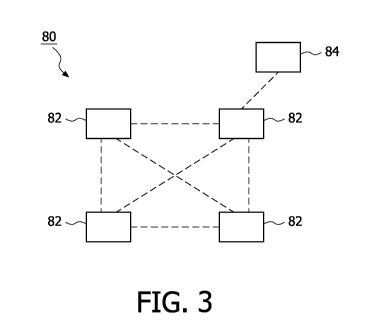
FIG. 3 is a block diagram of a motion detection system in accordance with the
present
invention. In this example, the motion detection system 80 includes a number
of RF units 82
in communication with each other as indicated by the dashed lines. In one
embodiment, at
least some of the RF units 82 communicate with each other wirelessly. In
another
embodiment, at least some of the RF units 82 are hard wired to communicate
with each other.
At least one of the RF units 82 can also be in communication with an optional
control unit
84. In another embodiment, the optional control unit 84 can be included in one
of the RF
units 82. The relative position of the RF units 82 and reflecting objects in
their vicinity
results in null points around the motion detection system 80. The RF units 82
can be fixed or
moveable as desired for a particular application. In one embodiment, at least
some of the RF
units 82 are contained in a single housing.
FIG. 4 is a flowchart of a motion detection method in accordance with the
present
invention. The method 100 includes transmitting a signal 102, such as
transmitting a signal
from a transmitter; detecting the signal at a first devicel04, such as a
receiver; determining
whether signal strength of the detected signal is less than an expected signal
strength 106;
transmitting at least one additional signal 108, such as transmitting at least
one additional
signal from the transmitter; detecting the at least one additional signal at
the first device 110;
determining whether signal strength of the detected at least one additional
signal is less than
the expected signal strength 112; and determining that the first device is in
a null point 114
when the signal strength of the detected signals is less than the expected
signal strength for a
CA 02752192 2011-08-10
WO 2010/092499 PCT/IB2010/050340
8
predetermined number of the detected signals. The method 100 can be carried
out with a
motion detection system as described in FIGS. 1-3 above.
Referring to FIG. 4, the first device, such as a receiver, can be one of a
number of
first devices, the expected signal strength can be the greatest signal
strength detected by the
first devices, so that one of the first devices is determined to be in the
null point and
stationary with respect to the transmitter when the signal strength of the
detected signal at the
one of the first devices is less than the expected signal strength less a
predetermined signal
strength offset for the predetermined number of detected signals. In one
example, the
predetermined signal strength offset is 15 dB. In another embodiment, the
transmitting a
signal comprises transmitting a signal from at least one of a number of second
devices, such
as a number of transmitters; the first device, such as a receiver, is one of a
number of first
devices; and each of the first devices is associated with one of the second
devices as a radio
frequency (RF) unit. Those skilled in the art will appreciate that there are
different ways to
determine the expected signal strength. In one embodiment, the expected signal
strength is
based on previous values of the detected signal strength, such as the previous
value, an
average of a number of the previous values, or a time weighted average of the
previous
values. In one embodiment, the expected signal strength is calculated by
modeling the
motion detection system and its surroundings. In one embodiment, the
predetermined
number of detected signals can be a predetermined number of consecutive
detected signals.
The method 100 can further include taking a predetermined action when the
first
device, such as a receiver, is determined to be in a null point and stationary
with respect to
the second device, such as a transmitter. In one embodiment, the predetermined
action is
reducing transmission frequency for the second device when the first device is
determined to
be in a null point. Reducing transmission frequency conserves power at the
transmitter. In
another embodiment, the predetermined action is reducing reception frequency
for the first
device when the first device is determined to be in a null point. Reducing
reception
frequency conserves power at the receiver. In another embodiment, the
predetermined action
is measuring a time the first device is determined to be in the null point,
and optionally
initiating an alarm when the time measured is greater than a predetermined
time. Measuring
the time permits analysis of the time a tracked movable component attached to
either the
transmitter or receiver spends at a fixed location. This can be used to study
how long a part
is in an assembly station or how long a medical patient is resting quietly in
bed. Initiating an
alarm provides notice of a condition of concern when the movable component has
not moved
CA 02752192 2011-08-10
WO 2010/092499 PCT/IB2010/050340
9
for a predetermined time, such as when the part has not moved from the
assembly station or
the medical patient has not been active.
The method 100 can further include detecting an increase of the signal
strength of the
detected signal when the first device is determined to be in the null point.
When the receiver
is determined to be in the null point and stationary with respect to the
transmitter, an increase
in signal strength can indicate the presence of a body near the transmitter
and/or receiver
which changes the location of the null point. The motion detection system can
be used as an
occupancy detector when the receiver is in a fixed position with respect to
the transmitter.
The transmitting at least one additional signal 108 can further include
transmitting
signals of different carrier frequencies. The null points are at different
locations at different
carrier frequencies, so a receiver can be in a null point with respect to the
transmitter at one
carrier frequency and not in a null point with respect to the transmitter at a
different carrier
frequency. Shifting signals over a number of carrier frequencies can find
different null points
at different carrier frequencies, which can then be used to determine when the
receiver is in a
null point and stationary with respect to the transmitter. In one embodiment,
the transmitting
is performed a number of times at a carrier frequency, then the transmitting
is performed a
number of times at another carrier frequency different from the original
carrier frequency.
In another embodiment, the carrier frequency is changed after each signal
transmission, so that the signal is transmitted at a first carrier frequency,
then a second carrier
frequency, then a third carrier frequency, et cetera. The transmitting can be
performed for a
predetermined number of carrier frequencies to determine the expected signal
strength. For
example, the expected signal strength can be the highest signal strength
detected for the
different carrier frequencies. In another example, the expected signal
strength can be a
statistical product of the signal strengths detected over the predetermined
number of carrier
frequencies, such as the average of the signal strengths detected over the
predetermined
number of carrier frequencies. When the detected signal strength at one of the
carrier
frequencies is less than the expected signal strength less a predetermined
signal strength
offset, that carrier frequency can be identified as being associated with a
null point. For an
example using five as the predetermined number of carrier frequencies, the
sequential signal
strengths detected for different carrier frequencies could be -10, -11, -40, -
5, and -10. The
expected signal strength can be the highest signal strength detected, i.e., -
5. The carrier
frequency with a detected signal strength of -40 indicates a carrier frequency
associated with
a null point, because the detected signal strength of -40 is less than the
expected signal
CA 02752192 2011-08-10
WO 2010/092499 PCT/IB2010/050340
strength of -5 less a predetermined signal strength offset, such as -15. The
detected signal
strength at the carrier frequency associated with a null point can be checked
for a
predetermined number of detected signals to determine whether the receiver is
in a null point
and stationary with respect to the transmitter. Those skilled in the art will
appreciate that null
5 points can occur for one receiver and transmitter pair at multiple carrier
frequencies.
One implementation of the method uses two signals as the predetermined number
of
detected signals for which it is determined that the receiver is stationary
with respect to the
transmitter. The method includes transmitting a first signal, such as
transmitting a first signal
from a transmitter; detecting the first signal at a number of first devices,
such as a number of
10 receivers; determining a greatest signal strength of the first signal
detected by the number of
first devices; and determining that one of the number of first devices is in a
null point when
signal strength of the detected first signal at the one of the number of first
devices is less than
the greatest signal strength less a predetermined signal strength offset. The
method further
includes transmitting a second signal, such as transmitting a second signal
from the
transmitter; detecting the second signal at the number of first devices, such
as the number of
receivers; and determining that the one of the number of first devices is in
the null point
when signal strength of the detected second signal at the one of the number of
first devices is
less than the greatest signal strength less the predetermined signal strength
offset. The one of
the number of first devices can be determined to be stationary when the one of
the number of
first devices is in the null point for the first signal and the second signal.
Those skilled in the
art will appreciate that the predetermined number of detected signals can be
selected to any
number as desired for a particular application considering such factors as
interference,
environment, the selected predetermined signal strength offset, the number of
approximately
collocated receivers available, the degree of control over carrier frequency
(e.g., the number
of frequency channels used), the relative impacts of a false positive or false
negative reading,
and the like.
While the embodiments of the invention disclosed herein are presently
considered to
be preferred, various changes and modifications can be made without departing
from the
scope of the invention. The scope of the invention is indicated in the
appended claims, and
all changes that come within the meaning and range of equivalents are intended
to be
embraced therein.