Note: Descriptions are shown in the official language in which they were submitted.
CA 02752202 2011-08-11
WO 2010/098939
PCT/US2010/022674
METHOD AND APPARATUS FOR PRE-SPINNING ROTOR FORGINGS
BACKGROUND OF THE INVENTION
TECHNICAL FIELD
[0001] This invention relates to methods and
machines for manufacturing rotors from forging and,
more particularly, to pre-spinning rotor forgings to
relieve forging induced residual stresses.
BACKGROUND INFORMATION
[0002] During normal operations gas turbine
engines may operate with high rotational speeds and
relatively high temperatures. Residual stresses from
a metal alloy forging process used in fabricating
turbine disks in the engine may relieve during engine
operation, such that the turbine disks may
undesirably expand. Such disk expansion may
adversely affect clearances between the rotor and
surrounding casing during engine operation.
[0003] In order to reduce occurrences and degree
of disk expansion, at least some known engine disks
are spun during the manufacturing process in a
near-finished condition to relieve the residual
= stresses in the disk or other rotor forging. This
process is known as pre-spinning of the disks
generally has the same effect on relieving the
residual stress as actual engine operation. Final
machining, such as, of mating or other features
and/or rabbets, for example, is performed after the
= pre-spinning process. Conventional pre-spinning
processes is a time consuming and costly process.
Moreover, because the high rotational speeds are
needed to relieve the residual stresses the rotor
forging and its mounting fixture must be balanced
which increases the complexity of the pre-spin
process.
[0004] Pre-spin machines provide the capability to
= - 1 -
CA 02752202 2011-08-11
WO 2010/098939
PCT/US2010/022674
spin rotating parts at speeds exceeding aircraft
engine core speeds which are about 13,000 RPM. In
= order for the machine to handle to amount of force
generated by the rotating parts unbalance, the
- rotating part, fixture, alignment, and spindle must
be balanced to values typically less than 500
gram-inches using separate balance machines.
Pre-spin machines are designed to be operated in a
speed range of about 5,000 RPM to 18,000 RPM and
balance machines between about 100 RPM and 1200 RPM.
Pre-spin machines are intended to hold the part
solidly and are typically of the soft-bearing type
which means the vibration response changes with
increasing speed. Balance machines roll the parts on
"knife-edge" bearings and try to maximize unbalance
sensitivity within the pedestals holding the
bearings. Pre-spin machines are not designed to
balance a part, typically they just spin parts to
high speeds and are designed to spin parts fast
enough for the part to actually fail.
[0005] Even if the rotating part and fixture can
be balanced separately in a stand-alone balance
machine, they must still be aligned properly in the
pre-spin machine. If not, reaching proper high
speeds may not be attainable. This problem then
creates significant cost prior to even pre-spinning
the rotating part. Costs may include machining of
rotating part to tight tolerances, balancing fixture,
properly aligning fixture, and properly aligning
pre-spin spindle. If unbalance is still too high,
process may have to be repeated many times to be able
= to achieve pre-spin speeds.
[0006] Another problem relates to the wear of the
pre-spin machine over time for rotating parts still
having high vibration levels. This may cause
premature failure of specific components or excessive
preventative maintenance costs to prevent these
failures. Failure within the pre-spin machine can
- 2 -
CA 02752202 2011-08-11
WO 2010/098939
PCT/US2010/022674
=
cause significant damage to the rotating part,
fixture, spindle, and machine. Yet another problem
with= having high unbalance and vibration in the
pre-spin machine is the potential for the rotating
part to shift within the fiXture causing higher
vibration during deceleration than during the
acceleration to top pre-spin speed. This concern can
also cause premature machine failure and rotating
part damage.
[0007] Thus, it is highly desirable to provide
apparatuses and methods that are less expensive and
less time consuming machine then conventional
machines and methods for balancing and pre-spinning a
,rotor forging to relieve forging induced stresses at
rotational speeds about or above maximum operational
speeds of a rotor part manufactured from the rotor
forging.
BRIEF DESCRIPTION OF THE INVENTION
[0008] A method and system for relieving forging
induced residual stresses in a rotor forging balances
a pre-spin machine with the forging mounted thereon
at a first =rotational speed and then pre-spins the
forging with it mounted on the machine at a
substantially greater second rotational speed. A one
per rev sensor is used for determining a weight
placement angle and a vibration sensor is used for
= determining an amount of weight to add to a spinning
assembly including the forging during the balancing.
[0009] An exemplary method for pre-spinning a
rotor forging to relieve forging induced residual
stresses in the rotor forging includes, mounting the
rotor forging on a pre-spin machine of a pre-spinning
system, balancing the pre-spin =machine with the rotor
forging mounted thereon at a first rotational speed,
and pre-spinning the rotor forging while mounted on
the pre-spin machine at a second rotational speed
substantially greater than the first rotational
- 3 -
CA 02752202 2011-08-11
WO 2010/098939 PCT/US2010/022674
speed. Using a one per rev sensor for.determining a
weight placement angle for the balancing of the pre-
spin machine with the rotor forging mounted thereon.
Using a vibration sensor for determining an amount
of weight to add to a spinning assembly including the
rotor forging during the balancing. Placing one or
more balance weights on an inside surface of the
rotor forging or elsewhere on a spinning assembly of
the pre-spinning system during the balancing wherein
the spinning assembly includes the rotor forging.
Using balance weights made of a high-density
non-metallic material placed on the inside surface
with an adhesive.
[0010] A more particular embodiment of the method
=
for pre-spinning further includes the second
rotational speed being about an order of magnitude
greater than the first rotational speed and more
particularly the first rotational speed being in a
first rotational speed range between about 100 RPM to
1200 RPM and the second rotational speed being in a
second rotational speed range between about 5,000 RPM
to 18,000 RPM.
[0011] An exemplary method for preventing over
spinning includes first determining rotational
inertia of a spinning assembly including the rotor
forging during a spin up period of the pre-spinning
by determining a rate of rotational acceleration vs.
torque applied to the spinning assembly and checking
the determined rotational inertia against a pre-
determined rotational inertia value for the rotor
forging. Then stopping the pre-spinning and/or
providing the operator with an error message if
during the checking the determined rotational inertia
exceeds the pre-determined rotational inertia value
for the rotor forging.
[0012] A pre-spinning system includes a pre-spin
machine operable for relieving forging induced
residual stresses in a rotor forging, a one per rev
- 4 -
=
CA 02752202 2011-08-11
WO 2010/098939
PCT/US2010/022674
sensor for determining a weight Placement angle for
balancing the pre-spin machine, a vibration sensor to
determine an amount of weight to add for balancing
the pre-spin machine, a control means for balancing
the pre-spin machine and controlling the pre-spin
machine during pre-spinning, and the control means
operably connected to the vibration and one per rev
sensors for receiving signals from the sensors. In a
more particular embodiment of the system the pre-spin
machine is operable to spin in a rotational speed
range between about 5,000 RPM to 18,000 RPM.
[0013] An exemplary embodiment of the system .
further includes the control means having a first
controller operable for controlling and displaying
rotor speed and vibration level of the pre-spin
machine during pre-spinning and a second controller
operable for balancing the pre-spin machine before
pre-spinning, the first controller being operably
connected to the vibration sensor, and the second
controller being operably connected to the vibration
sensor and one per rev sensors. The rotor forging is
mounted to a spindle of the pre-spin machine and one
or more balance weights are mounted on an inside
surface of the rotor forging or elsewhere on the
spinning assembly. The one or more balance weights
are made of a high-density non-metallic material
stuck on the inside surface of the rotor forging or
elsewhere on the spinning assembly with an adhesive.
[0014] In another more particular embodiment of
the system, the one per rev sensor includes a static
pickup co-operable with a rotatable trigger connected
to a spindle of the pre-spin machine. The spinning
assembly may include a spin arbor connected to a
spindle of the pre-spin machine and rotor forging
mounted to the spin arbor by a fixture.
[0015] The system may further include the control
means being operable for determining rotational
= inertia of a spinning assembly including the rotor
- 5 -
CA 02752202 2011-08-11
WO 2010/098939
PCT/US2010/022674
forging during a spin up period of the pre-spinning
by determining a rate of rotational acceleration vs.
torque applied to the spinning assembly and checking
the determined rotational inertia against a pre-
determined rotational inertia value for the rotor
forging. The control means may also be operable for
stopping the pre-spinning and/or providing the
operator with an error message if during the checking
the determined rotational inertia exceeds the pre-
determined rotational inertia value for the rotor
forging.
BRIEF DESCRIPTION OF THE DRAWINGS
[0016] FIG. 1 is an illustration of pre-spin
system and machine with a gas turbine engine rotor
forging mounted therein and containing a one per rev
vibration pickup.
[0017] FIG. 2 is a cross-sectional illustration of
the gas turbine engine rotor forging illustrated in
FIG. 1.
[0018] FIG. 3 is a cross-sectional illustration of
a turbine rotor made .from the gas turbine engine
= rotor forging illustrated in FIG. 1.
[0019] FIG. 4 is an illustration of a display of a
second controller for balancing a spinning assembly
of the pre-spin system and machine illustrated in
FIG. 1.
[0020] FIG. 5 is an illustration of a display of a
first controller for controlling and displaying rotor
speed and vibration level of the pre-spin system and
machine illustrated in FIG. 1.
[0021] ' FIG. 6 is an illustration of the display of
the first controller after balancing the pre-spin
system and machine.illustrated in FIG. 1.
[0022] FIG. 7.is an illustration of the display of
the first during a pre-spinning run of the pre-spin
system and machine illustrated in FIG. 1.
[0023] FIG. 8 is a schematic illustration of a
- 6 -
CA 02752202 2011-08-11
W02010/098939
PCT/US2010/022674
=
kinematic model of the pre-spin machine and a
spinning assembly including the gas turbine engine
rotor forging mounted therein.
[0024] FIG. 9 is a graphic illustration of rotor
speed acceleration versus time for the spinning
assembly including an exemplary gas turbine engine
rotor forging.
DETAILED DESCRIPTION OF THE INVENTION
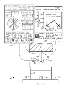
[0025] Illustrated in FIG. 1 is a pre-spinning
system 8 including an exemplary pre-spin machine 10
having a spin arbor 12 connected to a spindle 14 of
the pre-spin machine 10. The spindle 14 has an axis
75 of rotation, is vertically oriented, and is held
at some distance from an annular rotor forging 18 as
is well known in the art. The spin arbor 12 is
attached to a fixture 20 for holding the rotor
forging 18 which has an axial bore 13 illustrated in
cross-section in FIG. 2. The pre-spin machine 10
includes at least one controller (two are illustrated
herein).
[0026] The pre-spin machine 10 illustrated herein
is unique because it is designed to and is capable of
both spinning rotor forgings to very high rotational
speeds in ranges between 5,000 RPM to 18,000 RPM in
order to relieve forging induced residual stresses in
the rotor forgings and balance a spinning assembly 22
which includes the rotor forging 18, spindle 14, spin
arbor 12, and the fixture 20 while they are attached
to the pre-spin machine 10. The pre-spin machine 10
illustrated herein has a control means for balancing
the spinning assembly 22 and pre-spinning the rotor
= forging 18. An automated checking method and system
for assuring that the correct rotor forging was
loaded determines the acceleration rate of the
spinning assembly 22 including the rotor forging 18
and checking the determined acceleration rate against
a predetermined acceleration rate for the rotor
- 7 -
CA 02752202 2011-08-11
W02010/098939
PCT/US2010/022674
forging being pre-spun. The control means
illustrated herein includes a first controller 11 for
controlling and displaying rotor speed s and
vibration level of the pre-spin machine 10 during
pre-spinning as illustrated in FIGS. 1 and 5. The
control means illustrated herein further includes a
second controller 15 for balancing the spinning
assembly 22 before pre-spinning it as illustrated in
FIGS. 1 and 4.
[0027] The exemplary rotor forging 18 illustrated
herein is used to form a disk 30 of a first stage 32
of a high pressure turbine 34 as illustrated in FIG.
3 and which may be found in an aircraft high bypass
ration gas turbine engine. The rotor forging 18
illustrated in FIG. 2 is near net shape and includes
various features corresponding to final machined
features of the disk 30 illustrated in FIG. 3. These
features include the bore 13, hub 40, web 42, rim 44,
and cylindrical arm 46. Turbine blades 48 are
mounted in slots 50 machined in the rim 44 of the
disk 30 after the rotor forging 18 is spun to relieve
the forging induced residual stresses.
[0028] The pre-spinning system 8 may incorporate a
commercially available pre-spin machine 10. One
exemplary pre-spin machine 10 is a Schenck Trebel
Pre-Spin Machine which includes a M385 controller
serving as the first controller 11 for controlling
and displaying rotor speed s and vibration level v of
the pre-spin machine 10. The Schenck Trebel Pre-Spin
Machine and M385 controller are well known in the
industry for use in pre-spin systems. The second
controller 15, such as a CAB920 controller available
from Schenck illustrated in FIG. 4, is used to
balance the spinning assembly 22 by determining how
much weight or how many balance weights 56 to add to
the spinning assembly 22, as illustrated in FIGS. 1
and 2, and at what weight placement angle 66 as
illustrated in FIG. 4. The pre-spinning system 8 and
- 8 -
CA 02752202 2011-08-11
WO 2010/098939
PCT/US2010/022674
method of balancing the spinning assembly 22 uses the
pre-spin machine's existing vibration sensor 58 and
an additional one per rev sensor 60 a illustrated in
FIG. 1. Pre-spinning uses the pre-spin machine's
vibration sensor 58 to warn and/or avoid excessive or
dangerous vibrations during the high rotational speed
pre-spinning.
[0029] The one per rev sensor 60 is used to
determine a base angle from which the weight
placement angle 66 is determined and the machine's
vibration sensor 58 is used to determine how much
weight or how many balance weights 56 to add to the
spinning assembly 22 during balancing. The one per
rev sensor 60 illustrated herein includes a static
pickup 72 and a rotating trigger 74 set on a known
angle of on the spinning assembly 22. The static
pickup 72 illustrated'herein is a capacitance probe
and the rotating trigger 74 is a bolt screwed into
the spin arbor 12. The capacitance probe detects the
bolt every revolution and send the signal to the
controller to help determine the weight placement
angle 66. Other types of static pickups 72 include
vibration sensors, proximity switches, or light
sensors. Besides the bolt, other types of triggers
include set screws, reflective tape, and reflective
spots.
[0030] The weight placement angle 66 is where the
controller instructs the operator to place the
balance weights 56. The balance weights 56 are
preferably placed on an inside surface 62 of the
rotor forging 18 but may be placed elsewhere on the
spinning assembly 22. The balance weights 56 are
preferably not metallic pieces due to potential
failure of the metal at high pre-spin speeds greater
than 15,000 RPM and resulting damage that may occur
on the hardware. A high-density non-metallic
material is recommended instead. The non-metallic
material is such that it may be stuck on the inside
- 9 -
CA 02752202 2011-08-11
WO 2010/098939
PCT/US2010/022674
surface 62 of the rotor forging 18 or the spinning
assembly 22 or rotating part or assembly with
adhesive to prevent it from slipping. At high
speeds, the non-metallic material is forced outwardly
against the inside surface 62 and will stay in place
if on a surface parallel to the angle of rotation.
[0031] The controller is programmed to perform a
Fourier analysis on a vibration signal from the
vibration sensor 58 in the pre-spin machine 10 and
the a one per rev signal from the one per rev sensor
60. The result is instructions from the controller
for how much or how many balance weights 56 to add to
the spinning assembly 22 and at what weight placement
angle 66 or at what angular location around the rotor
forging 18 or elsewhere on the spinning assembly 22
as illustrated in FIG. 4.
[0032] Each separate rotor forging 22 must be
balanced before it is pre-spun. A calibration
process used for the balancing method developed for
the pre-spinning system 8 illustrated herein is an
iterative process. Each separate rotor forging 18 is
balanced before pre-spinning but calibration for the
type of part or rotor forging is calibrated usually
only once. For example all of the rotor forgings 18
for first stages 32 of high pressure turbines 34 must
be balanced and may use a.single calibration for that
type of part, namely the rotor forging 18 for a first
stage 32 of a high pressure turbine 34 for a
particular type of engine, e.g. a GE90.
[0033] The calibration is performed.initially with
a test weight to determine a magnitude of unbalance
(in gram-inches) correlating to magnitude of
vibration (% vibration level or mils of vibrations)
using the first controller 11 illustrated in FIG. 5.
= A phase angle is also determined relative to a
signal transmission from the one per rev sensor 60
using the second controller 15 to determine location
of weight placement. Since the vibration causes
- 10 -
CA 02752202 2011-08-11
W02010/098939
PCT/US2010/022674
bending within the components (spindle, fixture,
rotating part), the magnitude of unbalance
(gram-inches) per vibration level may vary. To
optimize this correlation, the sensitivity is set at
the most common unbalance seen by the assembly.
[0034] A non-linear calibration may be used to
calibrate the system 8 for balancing. For a linear
calibration the second controller 15 incorporating a
linear calibration would call for incremental weights
in for example grams (at a predetermined radius R at
a predetermined location Z along the axis 75 of
rotation of the spindle 14 of the pre-spin machine 10
for incremental vibration levels. Using the
non-linear calibration for balancing calls for non-
incremental weights to be added for incremental
vibration levels.
[0035] A non-linear calibration may be used to
= calibrate the system 8 for balancing. For a linear
calibration the second controller 15 incorporating a
linear calibration would call for incremental weights =
in for example grams (at a predetermined radius R at
a predetermined location Z along an axis 75 of
rotation of the spindle 14 of the pre-spin machine 10
.for incremental vibration levels. Using the
non-linear calibration for balancing calls for non-
incremental weights to be added for incremental
vibration levels.
[0036] The non-linear calibration is an iterative
process. Thus for higher vibration levels, the
calibration constant requires less mass or =weights
per vibration level than at lower vibration levels.
An example of using a non-linear calibration method
results in instructions displayed to the operator of
the pre-spin machine 10 as follows.
The number of weights determined by the second
controller 15 based on linear calibration determines
the number of weights the operator is instructed to
install using the non-linear calibration as follows:
- 11 -
CA 02752202 2011-08-11
WO 2010/098939
PCT/US2010/022674
if 5, install 4
if 4, install 3
if 3, install 3
if 2, install 3
if 1, install 2
The non-linear calibration typically results in less
balancing runs and time needed to balance the rotor
forging 18. Illustrated in FIGS. 5 and 6 are
examples of vibration levels before and after a
single calibration run illustrating the speed and
usefulness of the non-linear calibration method. The
non-linear calibration is stored in the second
controller 15 and Used for balancing each rotor
forging 18 of the same type such as those having the
same part number. The effectiveness of this method
is further illustrated in FIG. 7 which illustrates a
pre-spinning run at very high rotational speeds while
maintaining low acceptable vibrations.
[0037] As noted above, the pre-spin process
requires high rotational speeds to eliminate forging
induced residual stresses. In the aircraft gas
turbine industry, this process is used on several
different rotors for varying speeds. If a rotor is
incorrectly run to a different rotor program that
requires a higher speed, there is a risk of damage to
. the rotor, tooling, and pre-spin machine. This
problem is currently addressed manually. The
operator is required to load the correct program, and
to load the correct rotor with the program. There is
no on-machine check to assure that the correct rotor
has been loaded.
[0038] The exemplary method of balancing the
spinning assembly 22 and pre-spinning the rotor
forging 18 incorporates an automated checking method
and system for assuring that the correct rotor
forging was loaded by checking the acceleration rate
of the rotor forging. A kinematic model of the
spinning assembly 22 including the rotor forging 18
- 12 -
CA 02752202 2011-08-11
WO 2010/098939 PCT/US2010/022674
=
is illustrated in FIG. 8. Each rotor forging has a
unique rotational inertia J so a given torque T for
each rotor forging will accelerate different rotor
forgings at different rates.
[0039] The rotational inertia J times rotor speed
acceleration rate A equals the torque T minus losses
L of the kinematic model illustrated in FIG. 8.
Losses L include losses caused by vibration through
the damper D and bearing drag of the bearings B
illustrated in the model and may be represented by
equation 1, JxA=T- L. The lossesLcan be
ignored if the losses are low, or very consistent
between rotor forgings and thus equation 1 may be
reduced to equation 2, J x A = T. Thus, the
rotational inertia J is equal to torque T divided by
the rotor speed acceleration rate A. The rotor speed
acceleration rate A for the rotor forging 18 mounted
on the pre-spin machine 10 is derived from
information from the pre-spin machine 10 through its
controller. This information is a function of rotor
speed s of the spinning assembly 22 over time t that
the rotor speed s is measured. As the pre-spin
machine 10 is accelerated the rotor speed s of the
spinning assembly 22 changes over time t. The rotor
speed acceleration rate A is equal to a rotor speed
change DELTA s divided by a time interval DELTA t as
expressed in equation 3, A = (DELTA s) / (DELTA t) as
illustrated in FIG. 9.
[0040] The checking system automatically
calculates rotational inertia by checking the rate of
rotational acceleration vs. torque applied to the
rotor forging. The calculated rotational inertia is
then checked against a pre-determined and stored
=
required value for the program being executed. If
the rotational inertial does not match the stored
required value for the program being executed, the
machine will safely stop the program and provide the
operator with an error message. The checking system
- 13 - =
CA 02752202 2016-06-30
233266
may use one of the controllers to automatically
calculate the rotational inertia and check is against
the pre-determined stored required value for the
program being executed.
[0041] While there have
been described herein what
are considered to be preferred and exemplary
embodiments of the present invention, other
modifications of these embodiments falling within the
scope of the invention described herein shall be
apparent to those skilled in the art.
- 14 -