Note: Descriptions are shown in the official language in which they were submitted.
CA 02752321 2011-09-08
WO 2004/057305 PCTIDK2003/000926
A MILK CONVEYER DEVICE
Field of the invention
The invention relates to a milk conveyer device and in particular to a milk
conveyer device
comprising functionality for analysing a characteristic of the milk.
Background of the Invention
Milk obtained from milking of animals, such as cows or goats, has been a
central product
of agricultural production for many centuries. In recent decades, the use of
automatic
milking equipment has become predominant in industrialised countries due to
the
associated improvement in speed and efficiency.
In addition, it has become common place to analyse the milk from the animals
in order to
determine the milk quality and health of the animal. Therefore, some methods
have been
developed to allow for an analysis to be performed as part of an automated
milking
process. Specifically, analysis equipment has been developed that can
chemically analyse
milk samples taking from the milk produced by the milking. A chemical analysis
may be
performed at the site of the milking thereby allowing an individual farmer to
test and
analyse the milk as part of the milking process.
However, conventional milking systems are cumbersome to use in connection with
the
analysis equipment. For example, farmers typically have only one analysis
element but
may have more than one milking unit, each with milking attachment, such as a
set of teat
cups, for attaching to an animal to be milked. Therefore, performing an
analysis typically
involves disconnecting the analysis system from one milking unit, cleaning the
analysis
system, connecting it to another milking unit, generating a milk sample and
performing
the analysis. This is a very cumbersome operation, which requires significant
manual
intervention by the farmer. It is very time consuming, increases the workload
and reduces
the efficiency and productivity of the milking process.
Furthermore, insufficient cleaning results in the analysis samples being
polluted thereby
resulting in inaccurate or erroneous analysis results. In order to achieve
sufficient cleaning,
current health and hygiene standards require that the analysis equipment is
thoroughly
cleaned by flushing the system with significant amounts of water or of a water-
based
cleaning solution between analyses. Hence, conventional milking analysis
systems are
CA 02752321 2011-09-08
WO 2004/057305 PCTIDK2003/000926
2
required to be flushed with a water-based cleaning solution to remove remnants
from a
previous analysis.
Systems for extracting milk samples are known from other patents such as the
DE
19547892 patent wherein milk samples are extracted automatically. The milk
yield being
held in a collector vessel under vacuum, mixed with air when milking is over,
after which a
part of it is fed to a sampling vessel. The milk is delivered from the latter
vessel to an
analysing unit for immediate analysis. The milk remaining in the collector
vessel is only
extracted after analysis is complete, and is fed either to a pipe for usable
milk, or to one
for non-usable milk, dependent on the result. The first jets of milk when
milking starts can
be extracted via the pipe for non-usable milk. Before storing milk in the
sampling vessel,
milk can be directed via the latter into the pipe for non-usable milk, until
the preceding
sample is displaced.
Another example of a device for extracting milk sample is described in patent
DE 3502858,
which describes a device for drawing off milk samples from a delivery line,
the device is
used to divert milk into the sample flask by means of clocked pulses.
The object of the invention is to achieve, by means of the above mentioned
device, a
representative, virtually carry-over-free sample even if the delivery rate
changes during a
sampling operation.
A third example of a system for extracting milk samples is described in patent
DE 4343717
Al, which describes a method and apparatus for taking a milk sample
representative of a
volume of milk. The method and apparatus minimising the risk of contamination
of the
milk sample by milk originating from another supply. According to the
invention a major
component flow of milk is branched off from a main flow and directly conducted
to a
mixing tank. The mixing tank is flushed by a quantity of milk before the milk
branched off
in a minor component flow from the main flow and conveyed to the mixing tank
and
collected therein.
Hence, current systems for analysing milk have a number of disadvantages
including being
cumbersome, wasteful and time consuming. An improved milking arrangement for
analysing the milk would be advantageous.
CA 02752321 2011-09-08
WO 2004/057305 PCT/DK2003/000926
3
Summary of the Invention
Accordingly, the invention seeks to provide an improved analysing system for
analysing
the milk preferably alleviating or mitigating one or more of the disadvantages
of the prior
art singly or in combination.
According to a first aspect of the invention, there is provided a milk
conveyer device for a
milking arrangement having a milk storage reservoir; at least one milking unit
comprising
a milking attachment for attaching to an animal to be milked; a main milk
conduit, coupled
to the milking attachment and the milk storage reservoir, for conveying milk
from the
milking attachment to the storage reservoir; the milk conveyer device
comprising: an
analysis element for analysing at least one selected characteristic of an
analysis milk
sample generated from a milk analysis quantity; at least one sample unit
comprising a
sample element for extracting sample milk quantities from the milk of the main
milk
conduit; a sample reservoir coupled to the sample element for collecting the
sample milk
quantities to generate the milk analysis quantity; an analysis conduit,
coupled to the
sample reservoir and operable to be coupled to the analysis element, for
conveying the
milk analysis quantity from the sample reservoir to the analysis element,
wherein at least
part of the milk analysis quantity provides a cleaning effect of at least the
analysis conduit
thereby reducing residues of a previous milk analysis quantity conveyed to the
analysis
element through the analysis conduit.
It should be understood that, in any aspect of the present invention, a
milking unit with a
milking attachment may comprise at least one teat cup to be attached to an
animal to be
milked. For example, the milking unit may be implemented as a part of a so-
called
Voluntary Milk System which is commercially available from DeLaval
International AB. The
Voluntary Milk System comprises a milking robot which is ready to receive and
milk a cow
whenever a cow approaches the milking robot. A device with an optical system
automatically cleans every teat of the cow and mounts a set of teat cups to
the udder of
the cow. Thereby, measurement of the milked quantity of each individual udder
part is
made possible. The milked quantity of each individual cow is collected before
the quantity
is being led to the milk storage reservoir. Alternatively, the milked quantity
may be
disposed if, for example, the cell count is too high, which may be an
indication of mastitis.
In other embodiments of the invention, the milking unit and milking attachment
comprises
a conventional system where teat cups are attached to the udder of the cow in
a milking
parlour.
The inventors of the current invention have realised that contrary to the
current belief, a
self cleaning milk conveyer device may provide a number of advantages. Hence,
in
CA 02752321 2011-09-08
WO 2004/057305 PCT/DK2003/000926
4
contrast to the current understanding and prescribed standards for milking
arrangements,
the current invention provides a system wherein the milk being analysed itself
provides a
cleaning effect. Specifically, the cleaning effect may be applied to the part
of the milk
conveyer device involved in the analysis process, and in particular the
analysis conduit
S may be cleaned by at least a part of the milk analysis quantity itself. This
allows for an
analysis process to be applied that does not require separate cleaning fluids
to be used
between different analysis samples. Furthermore, as a cleaning effect is
provided by the
milk analysis quantity, a milk conveyer device may be implemented where no
separate
cleaning step of components of the device is required but rather the cleaning
is provided
by the milk being conveyed. Hence, the invention allows for a milking system
being
significantly less time consuming and/or cumbersome and/or wasteful than
conventional
milking systems. In particular, the invention provides for a system, the
operation of which
requires less labour work than the operation of conventional systems, and
which provides
a reduced or even eliminated degree of interruption in a milking/analysis
procedure. It
should be understood that the self-cleaning process is normally carried out
following
milking of each individual animal in a batch comprising a plurality of
animals, whereas
additional cleaning with a water-based cleaning solution is usually carried
out upon
completion of a milking process, i.e. between two batches.
In a typical embodiment, the cleaning effect is mainly of components
associated with the
sample reservoir and/or analysis conduit but in other embodiments the cleaning
effect
extends to other components and aspects of the milk conveyer device, including
the
analysis element and components associated therewith. In some embodiments, no
other
cleaning is provided for some of the components, but in other embodiments the
cleaning
effect of the milk analysis quantity may be complemented by other cleaning
steps. The
cleaning effect may be achieved by part of the milk analysis quantity flushing
out a
component of the analysis system prior to the milk analysis sample being
taken. Hence,
preferably impurities and remnants of previous milk samples are flushed out
before a milk
analysis sample is taken from the milk analysis quantity.
According to another feature of the invention, the cleaning effect comprises a
cleaning
effect of at least one of the analysis conduit and the analysis element.
Hence, the cleaning
effect is preferably associated with analysis part of the milking system, and
by using the
milk analysis quantity to provide a cleaning effect, the requirement for
additional or
alternative cleaning by using a cleaning solution can be significantly reduced
or eliminated.
According to another feature of the invention, the cleaning effect reduces a
concentration
of the previous milk analysis quantity in the analysis milk sample to less
than 3%, such as
less than 1.5%, less than 1% or less than 0.75%. Hence, preferably the milk
conveyer
CA 02752321 2011-09-08
WO 2004/057305 PCT/DK2003/000926
device is designed and dimensioned to provide for a substantial cleaning
effect. For
example, the volume of the milk analysis quantity may be designed such that it
causes
most of the previous milk analysis quantity to be flushed out before the
sample is taken.
Designing the system to result in less than 3% of a previous milk analysis
quantity to be
5. present in the measurement of the current milk analysis quantity results in
an acceptable
error of margin. This allows for no other cleaning process of the analysis
components to be
required thus significantly reducing the time consumption of the analysis
process.
According to another feature of the invention, the milk conveyer device
comprises no other
means for providing cleaning liquids to achieve a cleaning effect. Hence, by
designing the
system to require no other cleaning liquids than milk to be present, a more
hygienic
milking system with significantly less risk of contamination is achieved.
Specifically, as
preferably the only liquid in the system is milk, a leftover or mixing of milk
from different
milking or analysis processes will have little impact on the analysis quality
or analysis
accuracy. Specifically, it allows for all liquid in the system to be collected
in the same
container and thus reduces waste and increases hygiene, as no valve systems
are required
for water solutions or other external cleaning liquids during a milking
process.
According to another feature of the invention, the milk conveyer device is
operable to
prevent any other liquid than the milk analysis quantities to enter the
analysis conduit. The
analysis conduit is thus kept free of other liquids than milk thereby reducing
the risk of
contamination or mixing with other liquids. This improves the accuracy of the
analysis
process, and allows for the sample milk which is the only liquid in the
analysis conduit to
be fed directly to the storage reservoir. In preferred embodiments of the
invention, the
mechanical design of the system is simplified, as there is no need for valve
systems for
controlling the flow of other liquids but milk.
The flow through the analysis conduit is preferably controlled such that the
flow results in
a significant cleaning effect. The control of the flow may be dynamically
controlled and
involve a controller reacting to measurements from sensors. In other
embodiments, the
control of the flow is simply achieved through the design of the milk conveyer
device, for
example through the choice of parameters such as the cross area of the
analysis conduit or
the opening of valves. In most embodiments, the analysis conduit has a length
of 1 - 30 m
with an inner diameter of 1-5 mm.
According to another feature of the invention, the analysis element is
operable to generate
the analysis milk sample by extraction of a milk sample from the milk analysis
quantity
towards the end of a milk analysis quantity flow. In some embodiments, the
initial part of
the milk analysis quantity is used to clean elements of the milk conveyer
device and
CA 02752321 2011-09-08
WO 2004/057305 PCT/DK2003/000926
6
specifically the analysis conduit. The analysis milk sample is preferably
taken from the
latter part of the milk analysis quantity as the cleaning effect has
preferably had an effect
by then. The less contaminated milk analysis sample ensures an improved
analysis.
According to another feature of the invention, the sample reservoir comprises
a gas inlet
valve operable to open the sample reservoir to a gas thereby causing a
pressure to be
exerted on the milk analysis quantity in excess of the pressure of the
analysis conduit. One
suitable and implementation efficient method for controlling the flow of the
milk analysis
quantity in the analysis conduit is to control the pressure on the milk
analysis quantity in
the sample reservoir. This may preferably be achieved through controlling a
valve coupled
to a gas of higher pressure than in the analysis conduit. Preferably, the
analysis conduit is
at lower than atmospheric level and the gas is simply atmospheric air.
According to another feature of the invention, the milk conveyer device is
operable to
generate at least one gas bubble in a milk analysis quantity flow through the
analysis
conduit. The gas bubble, for example an air bubble, is preferably generated
inherently by
the system as part of the initialisation of the flow of the milk analysis
quantity. One option
is to let air into the analysis conduit prior to beginning the flow of the
milk analysis
quantity. Experiments have shown that the presence of air bubbles enhances the
cleaning
effect of the milk analysis quantity.
According to a second aspect of the invention and/or according to another
feature of the
invention, there is provided a milk conveyer device for a milking arrangement
having a
milk storage reservoir; at least one milking unit comprising a milking
attachment for
attaching to an animal to be milked; a main milk conduit, coupled to the
milking
attachment and the milk storage reservoir, for conveying milk from the milking
attachment
to the storage reservoir; the milk conveyer device comprising: an analysis
element for
analysing at least one selected characteristic of an analysis milk sample
generated from a
milk analysis quantity; a plurality of sample units, each of which comprises a
sample
element for extracting sample milk quantities from the milk of the main milk
conduit; a
sample reservoir coupled to the sample element for collecting the sample milk
quantities to
generate the milk analysis quantity; an analysis conduit, coupled to the
sample reservoir,
for conveying the milk analysis quantity from the sample reservoir to the
analysis element;
and a selector unit coupled to the plurality of analysis conduits of the milk
sample units,
the selector unit being operable to couple milk from one of the plurality of
analysis
conduits to the analysis element at a time.
Even though it is indicated above that the milk conveyer preferably comprises
both the
feature that at least a part of the milk provides a cleaning effect and the
selector unit it is
CA 02752321 2011-09-08
WO 2004/057305 PCT/DK2003/000926
7
to be understood that the present invention also encompasses milk conveyers
having only
the cleaning feature or the selector unit.
Preferably, the milk conveyer device thus comprises a plurality of milk sample
unit coupled
to a selector unit operable to couple milk from either of the milk sample
units to the
analysis element. The selector unit may e.g. be an Integral part of the
analysis element or
the analysis element may e.g. comprise two or more completely separate units.
Hence, the
selector unit and the analysis element may be two completely separate units
and may be
located at different physical locations. The selector unit may couple all,
most, some or only
a small proportion of the milk analysis quantity to the analysis element.
Further, the
analysis element may use only a small fraction of the received milk analysis
quantity for
the analysis.
The selector unit allows for a plurality of milk sample units to be
permanently coupled to
the analysis element and the selection of which milk sample unit to analyse
samples from
can be achieved by a simple control of the selector unit. This significantly
facilitates the
process of milking and analysing milk from a plurality of animals and thus
allows for a
much simpler, less cumbersome and time consuming process, as no interruption
of the
milking process is required.
According to another feature of the invention, the selector unit is a multi-
valve unit. This
provides for a suitable implementation of a selector unit.
According to another embodiment of the selector unit, it may comprise a
plurality of
sample stations, each sample station comprises an Inlet for the milk to be
tested, an outlet
for the superfluous milk and an access point, accessible by a collection
member for
extracting a milk sample. The selector unit may further comprise at least one
rinsing
station for rinsing of the collection member
According to another feature of the invention, the selector unit may have
access points
preferably comprising covers for preventing leakage of air into the system,
the cover
preferably being constituted by a penetrable plug preferably being made from
silicone,
rubber or the like, a valve or a moveable slide cover.
According to another feature of the invention, there is provided means for
generating a low
pressure in a chamber of the selector unit. Preferably a pressure differential
is created
between the sample reservoir and the chamber of the selector unit. The
pressure
differential may be created by lowering the pressure of the chamber of the
selector unit for
example by using a pump or may e.g. be achieved through mounting the selector
unit
CA 02752321 2011-09-08
WO 2004/057305 PCT/DK2003/000926
8
lower than the sample reservoir. The pressure differential biases the milk
analysis quantity
from the sample reservoir towards the selector unit and thus provides for a
suitable way of
establishing the flow.
According to another feature of the invention, the milk analysis element
further comprises
a dosage unit for generating an analysis dosage of the analysis milk sample.
Typically, only
a very small quantity of milk is required for the analysis and a dosage unit
provides the
advantage of being able to generate a suitable dose with an acceptable
accuracy.
According to another feature of the invention, the selector unit comprises: a
chamber, an
inlet to a chamber for each of the plurality of analysis conduits for each
milk sample unit,
each inlet being operable to provide a flow of milk analysis quantities into
the chamber, an
outlet coupled to the milk analysis element, and a moveable collection member
coupled to
the outlet of the selector unit, the moveable collection member being operable
to move a
collection element to the flow of a selected inlet thereby providing a flow
connection from
the selected inlet to the outlet. This allows for a suitable implementation of
a selector unit
and specifically allows for a selector unit that can easily be controlled.
According to another feature of the invention, the selector unit of the milk
analysis element
is operable to collect milk of the milk analysis quantities not being coupled
to the milk
analysis element, or to guide such milk to the storage reservoir.
The selector unit is coupled to the milk storage reservoir whereby the
collected milk is
conveyed to the storage reservoir. Hence, advantageously any left over milk
not coupled
to the analysis element may be fed to the storage reservoir. Consequently, the
left over
milk is not wasted but is combined with the milk fed directly to the storage
reservoir by
the main milk conduit. However, it should be understood that, in alternative
embodiments
of the invention, any left over milk may be disposed.
According to a third aspect of the invention, there is provided a milk
conveyer device for a
milking arrangement having a milk storage reservoir; at least one milking unit
comprising
a milking attachment for attaching to an animal to be milked; a main milk
conduit, coupled
to the milking attachment and the milk storage reservoir, for conveying milk
from the
milking attachment to the storage reservoir; the milk conveyer device
comprising: an
analysis element for analysing at least one selected characteristic of an
analysis milk
sample generated from a milk analysis quantity; at least one sample unit
comprising a
sample element for extracting sample milk quantities from the milk of the main
milk
conduit; a sample reservoir coupled to the sample element for collecting the
sample milk
quantities to generate the milk analysis quantity; an analysis conduit,
coupled to the
CA 02752321 2011-09-08
WO 2004/057305 PCT/DK2003/000926
9
sample reservoir and operable to be coupled to the analysis element, for
conveying the
milk analysis quantity from the sample reservoir to the analysis element; and
wherein a
flow of at least one milk analysis quantity in the analysis conduit has a flow
profile
comprising a higher flow rate in an earlier time period and a lower flow rate
in a later time
period.
The flow profile may be created through a dynamic controller measuring the
current flow
and controlling the flow accordingly. In other embodiments, the flow profile
may be
achieved through the design of the milk conveyer system. The flow rate within
each time
interval may be relatively constant or may vary within each time interval. The
flow rate
may for example refer to the highest flow rate in a time interval, the lowest
flow rate in a
time interval or to an average flow rate in a time interval. In one
embodiment, the flow
profile for the milk analysis quantity is a continually decreasing flow rate.
A higher flow rate in an earlier time interval may provide for an increased
cleaning effect.
Specifically, the milk analysis quantity may more effectively flush out
previous impurities
and milk remnants at a higher flow rate. However, a lower flow rate
facilitates flow control
and coupling and sample extraction through the analysis components of the
systems.
Hence, by having a varying flow rate the flow rate can be optimised for the
desired effects
at different times.
According to another feature of the invention, the sample reservoir comprises
an outlet
valve coupled to the analysis conduit.
Hence, advantageously the variation in flow rate may be achieved by control of
an outlet
valve from the sample reservoir. This provides an accurate and efficient
control that can be
achieved through simple mechanisms.
According to another feature of the invention, the sample reservoir comprises
a quantity
sensor for detecting a level of the milk analysis quantity remaining in the
sample reservoir,
and means for controlling the outlet valve in response to an output of the
quantity sensor.
In some embodiments a quantity detector may be used to detect the remaining
milk
quantity in the sample reservoir. When the quantity falls below a given level,
the valve
may be adjusted to provide a lower flow rate. This provides for a simple
mechanism that
can easily be implemented and allows the flow rate to be varied.
CA 02752321 2011-09-08
WO 2004/057305 PCT/DK2003/000926
According to another feature of the invention, the sample reservoir comprises
a gas inlet
valve for coupling a gas to the sample reservoir to provide a flow pressure to
the milk
analysis quantity.
5 Hence, advantageously the variation in flow rate may be achieved by control
of a gas inlet
valve from the sample reservoir. This provides an accurate and efficient
control that can be
achieved through simple mechanisms.
According to another feature of the invention, the sample reservoir comprises
a quantity
10 sensor for detecting a level of the milk analysis quantity remaining in the
sample reservoir,
and means for controlling the gas inlet valve in response to an output of the
quantity
sensor.
In some embodiments a quantity detector may be used to detect the remaining
milk
quantity in the sample reservoir. When the quantity falls below a given level,
the valve
may be adjusted to provide a lower flow rate. This provides for a simple
mechanism that
can easily be implemented and allows the flow rate to be varied.
According to a different feature of the invention, the milk sample unit is
operable to extract
sample milk quantities distributed over an extended period of a milking
process for a single
animal such that the milk analysis quantity comprise contributions from a
plurality of
sample milk quantities extracted. Specifically, the milk sample unit may be
operable to
perform proportional sampling of the milk.
Consequently, the milk analysis quantity is preferably generated from milk
analysis
samples taken over an extended period, which preferably has a duration
comparable to the
total time of a milking process. Hence, the milk analysis quantity may
comprise a
representative sample of the milk produced throughout the milking process and
thus
represent a suitable average of the milk produced. In milking of for example
cows, the
concentration of e.g. urea varies through the milking process. Hence, a sample
taken at a
given instant may not be representative as the concentration will depend on
when the
sample was taken. Therefore, a sampling over an extended period provides for
an
improved analysis to be performed and improves the diagnostic process based on
the
analysis. It will thus be understood that the proportional sampling mentioned
above may
either result in a sample volume which is proportional to the duration of the
milking
process, or in a sample volume which is proportional to the volume produced by
an animal
in a milking process. In an embodiment of the invention, the system may be
adapted to
foresee the volume of a subsequent milking process of an animal, based on
volumes of
CA 02752321 2011-09-08
WO 2004/057305 PCT/DK2003/000926
11
previous milking process of that animal, and to control the proportional
sampling
accordingly.
According to another feature of the invention, the milk conveyer device
comprises an
outlet valve between the sample reservoir and the analysis conduit, the outlet
valve being
operable to be closed during collection of sample milk quantities and opened
during
conveying of the milk analysis quantity to the analysis element,
The collection and emptying of sampled milk in the sample reservoir may
advantageously
be at least partly controlled by the gas inlet valve. Specifically, the gas
inlet valve may be
closed when the milk analysis quantity has been emptied from the sample
reservoir and
before the milk analysis quantity has been analysed. This allows for the
milking
attachment to be moved to a different animal, and a new milking process is
begun before
the milk analysis quantity of the first animal has been analysed.
According to another feature of the invention, the milk conveyer device
comprises a
conduit inlet gas valve coupled to the analysis conduit towards the outlet
valve and
operable to open when the outlet valve closes thereby providing a gas exerting
a pressure
on the milk analysis quantity in the analysis conduit.
Preferably, the flow of the milk analysis quantity in the analysis conduit may
be controlled
by a gas, controlled by the inlet gas valve. The gas may exert a pressure on
the milk
analysis quantity in the analysis conduit thereby assisting in producing the
flow. Especially,
this may allow for the passage to the sample reservoir to be closed without
creating a
vacuum hampering the flow of the milk analysis quantity in the analysis
conduit.
Furthermore, the valve may be closed in order to hamper or hinder the flow of
the milk
analysis quantity in the analysis conduit and can thus be used to retain at
least a part of
the milk analysis quantity in the analysis conduit. Hence, the inlet gas valve
may
significantly facilitate and enhance the control of the flow of the milk
analysis quantity in
the analysis conduit. Preferably the gas is atmospheric air.
According to another feature of the invention, the milk conveyer device
comprises a milk
flow sensor operable to detect milk flow in the analysis conduit; and a
controller for
controlling the inlet gas valve to close when the milk flow sensor has
detected that a given
amount of milk has been supplied through the analysis conduit. Thus, the inlet
gas valve is
preferably closed when the sample reservoir is empty of nearly empty.
A milk flow sensor may provide the input allowing a controller to control the
gas inlet valve
to regulate the flow of the milk analysis quantity as desired or required.
CA 02752321 2011-09-08
WO 2004/057305 PCT/DK2003/000926
12
According to another feature of the invention, the milk conveyer device
further comprising
a controller operable to close the inlet gas valve when at least a part of the
milk analysis
quantity is in the analysis conduit. This may specifically allow for the inlet
gas valve to be
controlled such that at least some of the milk analysis quantity is retained
in the analysis
conduit until such time that it is needed by the analysis element. In
particular, a part of
the milk analysis quantity may thus be stored in the analysis conduit while
the analysis
element is performing an analysis on another milk analysis quantity. When the
analysis
element is ready to analyse the milk analysis quantity, this may be extracted
from the
analysis conduit by any suitable method, for example by pumping it out or
opening the gas
inlet valve again. The advantage of improved flow control and thus improved
processing of
a plurality of milk analysis quantitys may thus be provided.
According to another feature of the invention, the analysis conduit is at a
lower pressure
than the sample reservoir during conveying of the milk analysis quantity to
the analysis
element. This allows for an easy to implement and efficient means of producing
a flow
from the sample reservoir to the analysis element.
According to another feature of the invention, the sample reservoir comprises
a mixer for
mixing the milk samples. This allows for an improved mixing of the milk
analysis samples
thereby ensuring that any sample from the milk analysis quantity used for
analysis is
representative of the entire sampled quantity.
According to another feature of the invention, the milk conveyer device
comprises at least
a first sensor for detecting gas bubbles in a flow of milk in the analysis
conduit. The
detection of gas bubbles or specifically air bubbles may be achieved through
use of for
example optical detectors or other suitable means. The detection of gas
bubbles allows for
the control of the flow to be improved as it provides additional information
as to whether a
milk analysis quantity is currently flowing past the first sensor.
According to another feature of the invention, the milk conveyer device
further comprises
a processor for determining a beginning of a milk analysis quantity flow from
the detection
of at least one gas bubble. Alternatively or additionally, the milk conveyer
device further
comprises a processor for determining an end of a milk analysis quantity flow
from the
detection of at least one gas bubble. The two functions may be implemented in
the same
processor and may be based on input from the same sensor. Hence, in an
embodiment
where the milk analysis quantities in the analysis conduit are interspersed by
gas bubbles
(e.g. air bubbles), the detection by a sensor of a new gas bubble may be taken
as a
determination that the end of a milk analysis quantity has passed the sensor.
When the
CA 02752321 2011-09-08
WO 2004/057305 PCT/DK2003/000926
13
sensor changes the indication to indicate that no gas bubble is present at the
sensor, this
may be taken as an indication that a beginning of a milk analysis quantity has
been
detected. The detection of beginning and/or ends of a milk analysis quantity
provides for a
very accurate flow control.
According to another feature of the invention, the milk conveyer device
further comprising
means for controlling the outlet valve in response to the detection of gas
bubbles by the
first sensor. This allows for improved flow control and especially allows for
very accurate
control of the flow of the milk analysis quantity in the analysis conduit. In
particular it
allows for the outlet valve to be closed when the first sensor detects an end
of the milk
analysis quantity thus ensuring that the entire milk analysis quantity has
exited the sample
reservoir.
According to another feature of the invention, the milk conveyer device
further comprises
a valve controller for controlling the inlet gas valve in response to the
detection of gas
bubbles by the first sensor. This allows for improved flow control and
especially allows for
very accurate control of the flow of the milk analysis quantity in the
analysis conduit. In
particular it allows for the gas inlet valve to be opened when the first
sensor detects an
end of the milk analysis quantity thus ensuring that the flow of the milk
analysis quantity
in the analysis conduit is continued when the outlet valve is closed.
According to another feature of the invention, the valve controller is
operable to close the
gas inlet valve in response to a detection of a gas bubble indicating an end
of a milk
analysis quantity flow. This allows for improved flow control and especially
allows for very
accurate control of the flow of the milk analysis quantity in the analysis
conduit. In
particular, a sensor may be situated along the analysis conduit at a location
at which the
trailing edge of the milk analysis quantity should stop in order to retain a
sufficient amount
of the milk analysis quantity in the analysis conduit for later analysis by
the analysis
element. If this sensor detects a gas bubble indicating the end of a milk
analysis quantity,
the gas inlet valve may be closed thus creating a vacuum in the analysis
conduit
preventing further flow. A very accurate system for retaining a desired volume
of the milk
analysis quantity in the analysis conduit may thus be achieved.
According to a different feature of the invention, the milk analysis quantity
is above 200
ml, in order to provide for the self-cleaning effect, and the milk sample
quantity is below
100 ml. Generally, the milk sample quantity should be as small as possible in
order to
have the smallest possible waste. These values have been found to be
advantageous and
allow for the advantages described to be achieved. In particular, they allow
for a suitable
cleaning effect to be achieved.
CA 02752321 2011-09-08
WO 2004/057305 PCT/DK2003/000926
14
Preferably, the analysis conduit comprises a pipe having an inner cross
sectional area of
between 1 to 5 mm and a length between 1 to 30 m. In a preferred embodiment of
the
invention, the conduit has an inner cross-sectional area of approximately 4 mm
upstream
of the selector unit, whereas the cross-sectional area of the conduit leading
from the
selector unit to the analysis element is approximately 1.5 mm. The analysis
conduit is
preferably made of low density polyethylene (LD-PE). The pipe may specifically
be a hose.
These characteristics provide for a suitable analysis conduit that is suitable
for most
implementations and provide suitable performance and characteristics of the
milk conveyer
device.
As an example, the at least one selected characteristic comprises a
concentration of urea
and/or progesterone in the milk analysis sample. With respect to diagnosing
mastitis, the
selected characteristic comprises an indication of Nagase or LDH content.
These
parameters are of high importance in determining the milk quality and/or the
health of the
animal and therefore provide important information to a user of the milk
conveyer device.
These and other aspects of the invention will be apparent from and elucidated
with
reference to the embodiments described hereinafter.
Brief Description of the Drawings
An embodiment of the invention will be described, by way of example only, with
reference
to the drawings, in which
FIG. 1 is an illustration of a milk conveyer device in accordance with a
preferred
embodiment of the invention.
Fig. 2 is an illustration of a sample reservoir with an element for collecting
sample milk
quantities into the reservoir.
FIG. 3 illustrates the milk conveyer device according to the invention
implemented in a
milking arrangement with a selector unit in accordance with an embodiment of
the
invention.
FIG. 4 is an illustration of a multi-valve selector unit in accordance with an
embodiment of
the invention.
CA 02752321 2011-09-08
WO 2004/057305 PCT/DK2003/000926
FIGs. 5 to 10 are illustrations of elements of a milk conveyer device in
accordance with an
embodiment of the invention in different phases of operation.
FIG. 11 is a schematic description of a milk conveyer device in accordance
with a preferred
5 embodiment of the invention. The figure illustrates the processes for: milk
collection,
rinsing of the sample hose and dumping of remaining milk
FIG. 12 is a schematic description of the milk conveyer device in figure 11.
The figure
illustrates the process for transfer of sample to an analyse instrument.
FIG. 13 is a schematic description of the milk conveyer device in figure 11
and 12. The
figure illustrates the process of cleaning the device.
FIG. 14 illustrates another embodiment of a multi-valve selector unit.
Description of Preferred Embodiments
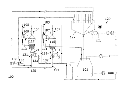
FIG. 1 is an illustration of a milk conveyer device 100 in accordance with a
preferred
embodiment of the invention.
The milk conveyer device is to be implemented in a milking arrangement which
comprises
a milk storage reservoir 101 which collects milk obtained from milking of
animals. The milk
is obtained from a number of milking points each of which has an associated
milking unit
(not shown). For clarity and brevity, FIG. 1 illustrates a specific example of
two milking
points but most implemented milking arrangements will typically have
significantly more
milking points.
Each milking unit comprises an attachment (not shown) for attaching to an
animal to be
milked. Such an attachment typically comprises teat cups. The attachment
attaches to for
example the teats of the udder of a cow, and provides a dynamic suction effect
resulting in
extraction of milk as is well known in the art. The milking arrangement
further comprises a
main milk conduit 103, 105 which guides the milk from the attachment to the
milk storage
reservoir wherein milk from the different milking units are collected.
The milk conveyer device further comprises a sample element 107, 109 coupled
to the
main milk conduit so as to be able to extract sample milk quantities from the
flow of milk
in the main milk conduit. In the preferred embodiment, the sample element 107,
109
comprises a member 110 (see FIG. 2) with a small aperture extending into a
cavity of the
main milk conduit 103, 105 allowing for small quantities of milk to enter the
aperture
CA 02752321 2011-09-08
WO 2004/057305 PCT/DK2003/000926
16
whereas the majority of milk bypasses the sample element to continue via the
main milk
conduit to the milk storage reservoir 101. Preferably the member 110 comprises
an arm
called knife, comprising at least one slit or aperture for receiving milk. The
slit is in contact
with the sample reservoir, thus the milk which has been extracted by the slit
in the
member 110 is preferably transferred to the sample reservoir.
Preferably the member 110 may be controlled in order to extract a
representative milk
sample from the milk flow in the main milk conduit. Thus during the whole
milking session
extract milk sample from the main milk conduit. The member may extract 2%, 4%,
6%,
8% or 10% from the milk flow in the main milk conduit. Furthermore the member
110,
may be two or more members with different dimensions in order to be able to
extract
different amount of milk from the main milk conduit. The member 110 is
designed for
extracting milk from a main milk flow.
The sample elements 107, 109 may further comprise two or more members 110 for
extraction of milk samples.
The aperture of the sample element is through a valve 111, 113 coupled to an
sample
reservoir 115, 117.The valves 111, 113 can open to allow milk to enter the
sample
reservoir 115, 117 or close to prevent the milk to enter the sample reservoir.
Hence, the
valves can be opened to sample milk flowing in the main milk conduit 103, 105
or closed
to stop the sampling of milk flowing in the main milk conduit 103, 105.
The milk flowing from the sample element 107, 109 to the storage reservoir 101
flows
preferably directly to the storage reservoir 101 (as indicated in Fig. 1 by
the dotted lines
connecting the storage reservoir 101 with the sample elements 107, 109) but
may be
buffered in case the result of the analysis of the milk is used as a criteria
for allowing milk
to flow into the storage reservoir 101. In the latter case, the milk conveyer
may comprise
a buffer having an outlet comprising a switch valve to guide the milk either
to the storage
reservoir 101 or to a waste reservoir.
The sample reservoir 115, 117 comprises a collection chamber wherein a
plurality of
sample milk quantities can be collected. The sample reservoir 115, 117
comprises an
outlet valve 119, 121 towards the lower end of the collection chamber. The
outlet valve
119, 121 is coupled to an analysis conduit 123, 125. When the outlet valve
119, 121 is
closed it allows the sample milk quantities to be stored in the collection
chamber 115, 117,
and when the outlet valve is opened, it allows for milk to exit the collection
chamber 115,
117 to enter the analysis conduit 123, 125.
CA 02752321 2011-09-08
WO 2004/057305 PCT/DK2003/000926
17
The milk is preferably mixed by a mixer in the vicinity of the bottom of the
sample
reservoir, preferably by utilising a membrane agitating the milk as described
in figure 11.
Hence, when a milking process is started the valve 111, 113 is opened to allow
sample
milk quantities to be extracted from the main milk conduit and enter the
collection
chamber. The outlet valve 119, 121 is closed to allow the sample milk
quantities to be
collected in the collection chamber. During a time interval, a milk analysis
quantity is
collected in the sample reservoir 115, 117 from the sample milk quantities
gathered during
the milking process. At the end of the time interval, the valve 111, 113 is
closed to
prevent further milk to enter the collection chamber from the main milk
conduit via the
sample element 107, 109.
The collection of the sample milk quantities from the main milk conduit 103,
105 may for
example be continued for a predetermined time, be manually terminated, be
terminated
when a suitable milk analysis quantity has been collected or be terminated
when milking of
an animal is completed which will cause the teat cups to drop off the udder of
the cow.
When the collection of the sample milk quantities, which constitute the milk
analysis
quantity, from the main milk conduit 103, 105 has terminated, the outlet valve
119, 121 is
opened. In the preferred embodiment, the pressure of the analysis conduit 123,
125 is
lower than that in the collection chamber and consequently the milk analysis
quantity will
flow from the collection chamber to the analysis conduit 123, 125.
Specifically, the pressure in the analysis conduit 123, 125 is maintained at a
lower
pressure than atmospheric pressure and the sample reservoir 115, 117 comprises
a gas
inlet valve 137, 139 which can open to subject the collection chamber to a
gas. The gas
provides pressure to the milk analysis quantity so as to bias it towards the
analysis
conduit. In the preferred embodiment, the gas is an atmospheric air and the
gas inlet
valve simply opens to the surrounding air thereby providing atmospheric
pressure. By
maintaining the pressure in the analysis conduit 123, 125 below atmospheric
level, this will
cause the milk analysis quantity to flow into the analysis conduit 123, 125.
In the preferred embodiment, each of the analysis conduits 123, 125 is coupled
to a
selector unit 127 through which it is possible to transfer milk from the
analysis conduit
123, 125 to a milk analysis element 129.
In operation, a computer means which controls the selector unit 127
consequently selects
which of the milking points are to be analysed by coupling milk from the
corresponding
sample element to the analysis element 129. The analysis element 129 performs
a
CA 02752321 2011-09-08
WO 2004/057305 PCT/DK2003/000926
18
chemical analysis to determine one or more characteristics of at feast part of
the milk
analysis quantity. Specifically, the chemical analysis may determine a
concentration of
urea or progesterone or any other appropriate characteristic in the milk
analysis quantity.
It is within the contemplation of the invention, that any suitable analysis
may be
performed on the milk analysis quantity in order to determine any suitable
parameter.
The inventors of the current invention have realised that in a milk conveyer
device in
accordance with an embodiment of the invention, a cleaning effect can be
achieved by the
milk analysis quantity in addition to the provision of conveying milk to an
analysis element.
Specifically, as the initial part of the milk analysis quantity when flowing
through the milk
conveyer device performs the function of flushing the remnants of previous
milk analysis
quantities. The analysis milk sample is generated from the latter part of the
milk analysis
quantity after the first part has cleaned the system.
The milk conveyer device is thus dimensioned such as to allow the milk
analysis quantity
to provide a significant cleaning effect. Specifically, the flow of the milk
analysis quantity
through the analysis conduit is dimensioned so as to provide the cleaning
effect.
In the preferred embodiment, the analysis conduit comprises a pipe or hose
having an
inner cross sectional area of approximately 4 mm upstream of the selector unit
and
approximately 1.5 mm between the selector unit and the analysis element. The
length of
the pipe or hose is between 1 and 30 m. For these values, the inventors have
realised that
for a milk sample quantity above 200 ml and a milk analysis quantity below 100
ml
sufficient cleaning of the milking system can be achieved by the milk analysis
quantity.
Specifically, a carry over of remnants from previous analysis processes can be
reduced to
less than 3% thereby providing a sufficiently small carry over to allow for a
sufficiently
accurate analysis to be performed.
Hence, in the preferred embodiment, no other liquid is used for cleaning the
milk conveyer
device between two consecutive milking processes, i.e. between two consecutive
cows
except for the milk analysis quantity itself, and the milk conveyer device is
constructed so
as to prevent that any other liquid enters the analysis conduit and the
analysis element. As
the only liquid present in the milk carrying parts of the system is milk, all
flows can be
collected in the storage reservoir without requiring any separation of the
milk from other
liquids. However, a water-based cleaning solution is used to clean the device
following
completion of milking of several animals. These animals may constitute a so-
called batch.
In the preferred embodiment the control of the valves in the milk conveyer
device is
furthermore such that at least one gas or specifically air bubble is generated
in the milk
CA 02752321 2011-09-08
WO 2004/057305 PCT/DK2003/000926
19
flow in the analysis conduit. This enhances the cleaning effect provided by
the milk
analysis quantity.
In the preferred embodiment, the selector unit 127 is a multi-valve unit.
Furthermore, as
illustrated in FIG.1, the selector unit 127 is coupled to the storage
reservoir 101 such that
the milk not being supplied to the analysis element 129 is collected in the
storage reservoir
101.
FIG. 3 illustrates the milk conveyer device according to the invention
implemented in a
milking arrangement with a selector unit 127 in accordance with an embodiment
of the
invention. The selector unit 127 constitutes a node receiving milk through
analysis
conduits 203 from a plurality of milking points 201 each having an associated
sample unit.
Under control of the computer means, the selector unit 127 is connected to the
analysis
element 129 and the storage reservoir 101. The selector unit selects a single
analysis
conduit to be coupled to the analysis element 129 for generation of a milk
sample to be
analysed. Any overflow from this analysis conduit is collected and directed to
the storage
reservoir.
FIG. 4 is an illustration of a multi-valve selector unit 300 in accordance
with an
embodiment of the invention. The selector unit 300 comprises a plurality of
inlets 301 to
which the analysis conduits are connected. The selector unit 300 further
comprises a
chamber 303 into which the milk from the inlets 301 flow. The chamber has an
associated
outlet 305 through which the overflow milk is collected and fed to the storage
reservoir.
The selector unit 300 comprises a moveable member or collection element shown
in the
form of an arm 307. The arm 307 is axially and pivotally mounted such that it
is able to
rotate a collection member 309 to any of the inlets 301 thereby providing a
coupling
between the inlet 301 and the collection member 309. The collection member 309
is by the
aid of the arm 307 coupled to an outlet 311 through which a part of the
analysis quantity
is fed to the analysis element. The arm 307 can be rotated by appropriate
means, for
example by a step motor 313 such that the coupling between one of the inlets
301 and the
outlet 311 to the analysis element can be controlled by control of the step
motor 313.
In the preferred embodiment, a pressure differential is created between the
sample
reservoirs and the selector unit to facilitate the flow from the sample
reservoirs to the
selector unit. In some embodiments this pressure differential may be provided
by creating
a reduced pressure in the chamber of the selector unit, for example by use of
a pump. In
other embodiments, a pressure differential is created by gravity, e.g. by the
selector unit
being mounted lower than the sample reservoirs.
CA 02752321 2011-09-08
WO 2004/057305 PCT/DK2003/000926
In the preferred embodiment, the analysis element generates a suitable
analysis milk
sample for the analysis from the milk analysis quantity. Typically, the
quantity of the
analysis milk sample may be in the order of 30 to 50 ml whereas typically only
0.01 ml of
milk is used for the actual analysis.
5
The operation of the milk conveyer device and in particular the flow of the
milk analysis
quantities is described in the following with specific reference to FIG. 1 and
FIGs. 5 to 10.
FIGs. 5 to 10 is an illustration of different components of the milk conveyer
device in
accordance with an embodiment of the invention in different phases of
operation.
10 Specifically, FIGs. 5 to 10 illustrate a sample reservoir 115, an analysis
conduit 123 and a
selector unit 127.
FIG. 5 illustrates the situation immediately prior to the outlet valve of the
sample reservoir
being opened. The sample process has been finished and the sample reservoir
comprises
15 the milk analysis quantity.
FIG. 6 illustrates the situation after the outlet valve 119 has been opened.
Due to the
pressure differential between the sample reservoir and the chamber of the
selector unit,
the milk analysis quantity has started to flow through the analysis conduit.
FIG. 7 illustrates the situation after the entire milk analysis quantity has
left the sample
reservoir. The initial part of the milk analysis quantity has reached the
selector unit and is
collected in the chamber and is directed to the storage reservoir. In this
situation, no milk
is fed to the analysis element. Rather the initial part of the milk analysis
quantity is
performing a cleaning function cleaning the analysis conduit and removing
carry over from
the previous milk analysis quantity.
In the preferred embodiment, the milk conveyer device further comprises a
first sensor
131, 132 (see FIG. 1) close to the outlet valve of the sample reservoir. It is
contemplated
that the sensor 131, 132 may be left out e.g. as shown in FIG. 11-13. The
sensor is
operable to detect air bubbles in the flow in the analysis conduit. In
addition, the milk
conveyer device comprises a conduit inlet gas valve 133, 134 which is coupled
to the
analysis conduit. The coupling of the inlet gas valve to the analysis conduit
is towards the
outlet valve of the sample reservoir. When the sensor 131, 132 detects an air
bubble
indicating that the end of the milk analysis quantity has passed the sensor,
the outlet
valve of the sample reservoir closes such that the sample reservoir is ready
to collect new
milk sample quantities. At the same time the conduit inlet gas valve 133, 134
opens to
provide a gas exerting a pressure on the milk analysis quantity in the
analysis conduit.
CA 02752321 2011-09-08
WO 2004/057305 PCT/DK2003/000926
21
This causes the flow of the milk analysis quantity to continue in the analysis
conduit. In the
preferred embodiment, the inlet gas valve simply opens to atmospheric air.
In the preferred embodiment, the milk conveyer device further comprises a
second sensor
135, 136, which is located at a distance from the outlet valve further along
the analysis
conduit 123, 125 towards the selector unit 127. When the second sensor 135,
136 detects
an air bubble indicating that the end of the milk analysis quantity has passed
the second
sensor 135, 136, a control mechanism closes the conduit inlet gas valve 133,
134.
Following closing of the inlet gas valve 133, 134, the pressure upstream of
the milk
analysis quantity, i.e. the pressure behind the milk analysis quantity when
seen in the flow
direction, will, for a short while, remain higher than the pressure downstream
of the milk
analysis quantity. Thus, the milk analysis quantity continues while no air is
allowed
through the inlet gas valve whereby a vacuum develops upstream of the milk
analysis
quantity. The pressure of the upstream vacuum increases as long as the milk
analysis
quantity continues to flow. However, when the pressure of the upstream vacuum
is equal
to the pressure of the vacuum downstream of the milk analysis quantity, i.e.
when the
pressure differential is equalised, flow of the milk analysis quantity stops.
Consequently as
shown in FIG. 8 a static situation is obtained wherein a remaining part of the
milk analysis
quantity is left in the analysis conduit. The remaining part of the milk
analysis quantity
may remain in the analysis conduit until the selector unit is ready to forward
it to the milk
analysis element. In a specific embodiment, the second sensor 135, 136 is
located such
that the analysis conduit extends for approximately three to four meters from
the second
sensor 135, 136 to the selector unit. For the specific embodiment, this
corresponds to
approximately 50 ml of the milk analysis quantity remaining in the analysis
conduit.
FIG. 9 illustrates the situation after the moveable arm of the selector unit
has been moved
to the inlet of the analysis conduit. In this situation, the appropriate inlet
of the selector
unit is coupled to the outlet 311 leading to the analysis element 129. The
analysis element
comprises a pump, which is operable to pump the remaining part of the milk
analysis
quantity out of the analysis conduit and into the analysis element 129 as
shown in FIG. 9.
The remaining part of the milk analysis quantity, or at least a portion
thereof, may be used
for the analysis. Said portion of milk is called an analysis milk sample.
As illustrated in FIG. 10, when at least some of the remaining part of the
milk analysis
quantity has been fed to the analysis element 129, the selector unit 127 may
be switched
to a different inlet to provide a different analysis quantity to be
transferred to the analysis
element 129.
CA 02752321 2011-09-08
WO 2004/057305 PCT/DK2003/000926
22
It will be clear that a milk conveyer device in accordance with the described
embodiment
allows for analyses to be performed for a plurality of milking points with
very little effort
and time consumption. Especially, very little manual control and interaction
is required.
Further, the milking system provides a self cleaning effect from the milk
itself thereby
eliminating the requirement for a separate cleaning liquid.
In the preferred embodiment, the flow through the analysis conduit 123, 125 is
controlled
such that the flow of the milk analysis quantities have a flow profile
comprising a higher
flow rate in an earlier time period and a lower flow rate in a later time
period. Specifically,
the initial flow rate is higher than the latter flow rate thereby providing an
increased
cleaning effect of the initial part of the milk analysis quantity and
increased flow control for
the latter part of the milk analysis quantity while providing for rapid
emptying of the
sample reservoirs.
The flow profile is specifically achieved by controlling the opening of one or
more of the
valves associated with the sample reservoir. In a preferred embodiment, the
flow profile is
controlled by providing a pulsating open/close signal to the conduit inlet gas
valve 133,
134.
Additionally or alternatively, the conduit gas inlet valve 133, 134 is
operable to be opened
wider during the earlier time interval than during the second time interval.
In the preferred embodiments the sample reservoir comprises a quantity sensor
for
detecting a quantity of the milk analysis quantity remaining in the sample
reservoir. A
control mechanism is operable to open and close the valves in response to the
output of
this detector. Specifically, during emptying of the sample reservoir the
quantity detector
may detect that the remaining milk analysis quantity falls beneath a given
threshold, and
one or both valves may be closed to some extent thereby limiting the flow of
the milk
analysis quantity.
In some embodiments different flow rates are achieved by a different gas
pressure applied
to the milk analysis quantity through the gas inlet valve 137 and the conduit
inlet gas
valve 133, 134. In this way the flow rate may be reduced when the sample
reservoir outlet
valve is closed and the conduit inlet gas valve 133, 134 is opened.
In the preferred embodiment, the sample unit is arranged to extract sample
milk
quantities distributed over an extended period of a milking process.
Preferably the sample
milk quantities collected into a single milk analysis quantity are extracted
regularly from a
time towards the beginning of the milking process to a time towards the end of
the milking
CA 02752321 2011-09-08
WO 2004/057305 PCT/DK2003/000926
23
process. Hence, preferably the sample unit performs a proportional sampling of
the milk of
the main milk conduit.
In the preferred embodiment, the sample reservoir further comprises a mixer
for mixing
the milk sample quantities. Specifically, the mixer may be a membrane mixer,
which is
pulsated to provide turbulence in the milk stored in the sample reservoir
thereby causing a
mixing effect.
FIG. 11 illustrates a preferred embodiment of a milk conveyer device according
to the
Invention wherein the processes of milk collection, rinsing of the sample hose
BO and
dumping of the remaining milk is illustrated.
During the milking process the valve Al between the sample element 107, 109
and the
sample reservoir 115 is opened. Approximate 2%, 4%, 6%, 8% or 10% of the yield
is
conducted from the sample element to the sample reservoir. The milk is
gathered during the
whole milking process to obtain a representative sample. The equipment
preferably manages
yields from 7 to 25 kg resulting in sample quantities preferably from 280 to
1000 ml.
The A2 membrane close to the outlet of the sample reservoir is agitating the
milk
entering the sample reservoir in order to provide a proper mixing of the milk.
When the milking process is finished, the process of rinsing of the sample
hose BO
starts. The valve 131 is closed in order to close the channel to the sample
element 109 that
also provides vacuum for the sample reservoir. Another valve B1A at the top
opens up for air
inlet.
The valve B2 at the bottom of the sample reservoir is opened and milk from the
sample
reservoir rinses the sample hose BO in order to reduce carry-over from
previous samples. To
improve the rinsing effect, rinsing milk may be mixed with small amounts of
air provided from
the speed valve C2.
When the preferred amount of milk sample has been extracted from the sample
reservoir
115 the remaining milk from the reservoir may be dumped directly into the main
milk
pipeline/conduit M after which the milking equipment is ready for the next
cow.
The milk sample is brought forward in the hose BO with short intervals of air
inlet from the
speed valve C2 which in turn is connected to the Air/Cleaning pipeline AC. An
air sensor C3
register when the last part of the milk sample passes and shuts of the speed
valve C2.
Thus the remaining amount of the milk sample is left inside the sample hose
until the
system is ready to send it to the analysis instrument.
CA 02752321 2011-09-08
WO 2004/057305 PCT/DK2003/000926
24
Heating cables may be provided in order to keep the samples in temperature
close to 35 C.
Shown in the figure is a solution based on circulated hot water C4. However
other suitable
solutions such as cables etc, for keeping the milk sample warm can also be
used.
The first part of the sample remaining inside the sample hose is used for
rinsing of the
sample hose and only the last part of milk is used for analyzing. The first
part of the milk,
which is used for rinsing the sample hose, may preferably be brought back to
the main milk
conduit M. The third main pipeline is the vacuum pipeline VP.
FIG. 12 illustrates the embodiment shown in figure 11, wherein the process of
transferring
a milk sample to an analysis instrument is illustrated.
The selector arm D1 inside the selector unit 127 is rotated by a stepper motor
S to the desired
position and then connected (preferably lifted with vacuum) to that samples
port. Further
more the shut-off valve D2 is opened and the switch valve D3 is switched from
cleaning to
analyzing position. The peristaltic pump D4 is activated and the milk sample
is pumped
towards the analyze Instrument Al. Air inlet through the speed valve D5 avoids
vacuum in
the system. Preferably the sample reservoir 115 is disconnected from air and
test hoses
which admits milking of another cow to take place. Pressure shocks from the
pump D4 are
absorbed by a section of flexible hose D6. After that the milk sample passes
through a
filter D7 in order to remove particles that could damage the function of the
analyze
instrument. After each sample the filter material is fed forward in order to
avoid jamming of
the filter. When the last sample has passed the filter a number of feeding
operations are
performed in order to remove used filter material from the filter feeder.
Preferably the filter
feeder further comprises means for cutting and collection of used filter
material.
The test sample is led forward inside a hose D8 and when the entire sample has
passed
the shut-off valve D9 (preferably time controlled), is shut off and air is
provided from an
adjacent electrical operated air inlet valve. D10 is a reservoir containing
milk samples from
cows, which have been treated with antibiotics. The milk in the reservoir D10
is preferably
sucked into the system and transferred to the analysis instrument.
The hose between the selector unit 127 and the analysis instrument is
preferably cleaned in
the same manner as the rest of the system in order to avoid carry-over from
the earlier milk
sample. Thus the first part of the milk sample entering the hose provides the
cleaning effect
and the sample which is used in the analysis instrument is extracted from the
last part of the
milk sample conveyed to the analysis instrument.
FIG. 13 illustrates the embodiment shown in figure 11-12, wherein the process
of cleaning
Is illustrated. Cleaning of the milk conveyer device is preferably executed
with a portion of
CA 02752321 2011-09-08
WO 2004/057305 PCT/DK2003/000926
cleaning liquid diverted to clean the sample container El. The cleaning water
in the sample
reservoir 115 then alternates between E2 passing the dump pipe DP and the milk
sample
hose BO. The speed valve E3 is opened intermittent to release portions of
cleaning water for
rinsing the mushroom valve E2. The channel with the sample hoses is warmed up
with the
5 heating means E4, such as warm water or the alike, in order to improve the
cleaning effect.
A mushroom valve E5 located in the bottom part of the selector unit 127 is
opened up to clean
the selector unit. Cleaning water also flows through the switch valve E6 to
clean the selector
arm.
10 The hose D8 connected to the analyze instrument, is cleaned with a small
cleaning unit F that
can be used separate from the milking conveyer device. With the switch valve
E6/F1 in
cleaning mode (default mode), hose D8 is connected to the cleaning unit
containers F2, F3
and F4. Detergent F4 is added to heated water in a second container F3 and
pumped out for
cleaning. Rinsing water is filled up, heated and pumped out through the
system. Finally, the
15 hose is rinsed with fresh water. The valve F1 is preferably a secure valve
thus if it breaks it
returns to a safe mode in order to avoid chemicals to enter the milk conveyer
system.
FIG. 14 illustrates another embodiment of a multi-valve selector unit 141 in
accordance
with an embodiment of the invention. The selector unit comprises a block 141
comprising a
20 plurality of sample stations 142. Each sample station comprises an inlet
143 for the milk to
be tested, an outlet 144 for the superfluous milk not used in the test and an
access point
149, which can be accessed by a collection member 147 such as a needle,
pipette or the
like for extracting a milk sample. Each access point may be covered with a
cover 145 in
order to prevent leakage of air into the system. The cover may be penetrated
by a part of
25 the collection member 148.
The collection member can be moved across all the sample stations and also to
a cleaning
station 146 for cleaning of the collection member 147, 148. Furthermore the
collection
member can be moved to an application station (not shown) for application of a
collected
milk sample on to a test stick.
Although the present invention has been described in connection with the
preferred
embodiment, it is not intended to be limited to the specific form set forth
herein. Rather,
the scope of the present invention is limited only by the accompanying claims.