Note: Descriptions are shown in the official language in which they were submitted.
CA 02752705 2015-08-10
FRIED104-1CA
1
SHROUDED TURBINE BLADE DESIGN
This patent application claims the benefit of U. S. Provisional Patent
Application No.
61/028,545, entitled Provisional 2-08: One-directional bearings, Large and
Small Wind,
Hydro, Blade Design, filed February 14, 2008 and No. 61/058,235, Provisional 6-
08:
Improvements to renewable energy devices, filed June 3, 2008.
SUMMARY OF THE INVENTION
The present invention successfully addresses the shortcomings of the presently
known
configurations by providing a set of criteria for improving the performance of
blades in a
shrouded turbine.
It is now disclosed for the first time a substantially10-meter diameter blade
for use
with a shrouded turbine with a shroud of substantially 1-meter chord length,
in any
proportional value, comprising the maintenance of geometric similitude and the
advance ratio
(Js =V,s'inD), with the following parameters (r being the radial coordinate, R
the radius, with
1.000 being the tip of the blade, c the chord length, D the diameter, t the
section thickness, f
the section camber, 0 the geometric pitch angle, P the pitch), with a
deviation of 10% of the
value for any point, for the values in any individual column or for any
combination of any
group of two or more columns in relation to the r/R value, proportional to any
size blade:
(Table 1)
r/R c/D t/c f/c (deg) P/D c (m) t (m) f (m)
0.150 0.10490 0.18000 -0.03137 50.000 0.56160 1.049 0.189 -0.033
0.200 0.10450 0.17412 -0.04396 40.987 0.54593 1.045 0.182 -0.046
0.300 0.10249 0.16235 -0.05424 28.650 0.51493 1.025 0.166 -0.056
0.400 0.09908 0.15059 -0.05551 21.077 0.48431 0.991 0.149 -0.055
0.500 0.09411 0.13882 -0.05370 16.509 0.46555 0.941 0.131 -0.051
0.600 0.08724 0.12706 -0.05056 13.862 0.46514 0.872 0.111 -0.044
0.700 0.07829 0.11529 -0.04743 12.168 0.47418 0.783 0.090 -0.037
CA 02752705 2015-08-10
FRIED104-1CA
2
0.800 0.06764 0.10353 -0.04363 11.211 0.49814 0.676 0.070 -0.030
0.900 0.05554 0.09176 -0.03989 11.435 0.57193 0.555 0.051 -0.022
0.925 0.05230 0.08882 -0.03908 11.813 0.60780 0.523 0.046 -0.020
0.950 0.04896 0.08588 -0.03858 12.701 0.67266 0.490 0.042 -0.019
0.975 0.04553 0.08294 -0.03879 14.637 0.79998 0.455 0.038 -0.018
1.000 0.04196 0.08000 -0.04002 18.000 1.02077 0.420 0.034 -0.017
According to another embodiment, the blade is for use in a liquid.
According to another embodiment, the blade is surrounded by a foil shape.
According to another embodiment, the shroud is a Farb foil.
According to another embodiment, the blade is part of a system of 3 blades.
According to another embodiment, the rpm is adjusted to 25-30 in a 3-meter per
second flow in a liquid.
It is now disclosed for the first time a turbine comprising:
a. at least one shrouded blade, wherein the ratio of rpm to diameter at a 3-
meter per
second flow in a liquid is 2.2 to 3.2.
It is now disclosed for the first time a turbine, comprising:
a. an NACA series blade,
b. a shroud.
Such a type of blade is particularly effective.
According to another embodiment, the shroud comprises a C foil, with a margin
of
10% for any single point.
According to another embodiment, the shroud comprises a Farb foil, with a
margin of
10% for any single point.
According to another embodiment, the shroud is a partial foil.
According to another embodiment, the blade comprises an NACA 44 series foil.
CA 02752705 2015-08-10
FRIED104-1CA
3
It is now disclosed for the first time a shrouded blade, wherein the tip does
not have
the lowest Phi value.
According to another embodiment, the Phi value of the tip is at least 3
degrees higher
than the section with the lowest Phi value.
According to another embodiment, the Phi value increases by at least 5 degrees
between an r/R ratio of 0.8 to 1Ø
It is now disclosed for the first time a shrouded blade, wherein the P/D ratio
at the tip
is greater than 0.7.
According to another embodiment, the ratio is greater than 1Ø
It is now disclosed for the first time a shrouded blade, wherein the Phi value
starts to
increase at a point 60-90% of the length from the center to the periphery.
It is now disclosed for the first time a shrouded blade, wherein the P/D ratio
starts to
steadily increase starting from any point within 40-90% of the distance from
the center to the
periphery.
It is now disclosed for the first time a shrouded blade, with the following
parameters,
in any proportional value, with a deviation of 10% of the value for any point,
for the values in
any individual column or for any combination of any group of both columns in
relation to the
r/R value, proportional to any size blade: (Table 2)
r/R c/R Phi
0.13820 0.295890 44.95916
0.15596 0.286650 43.01705
0.18667 0.270180 39.76573
0.22496 0.250070 36.09830
0.26726 0.229480 32.10272
0.31156 0.210200 29.05061
0.35670 0.192960 26.41902
0.40198 0.177880 24.53083
0.44693 0.164780 22.56773
0.49122 0.153390 20.90665
0.53458 0.143480 19.51586
CA 02752705 2015-08-10
FRIED104-1CA
4
0.57680 0.134850 18.35955
0.61770 0.127330 17.38834
0.65711 0.120770 16.56282
0.69490 0.115050 15.84945
0.73092 0.110060 15.22573
0.76507 0.105690 14.70786
0.79723 0.101840 14.30656
0.82731 0.098452 14.00050
0.85520 0.095469 13.78477
0.88082 0.092852 13.64459
0.90411 0.090573 13.56008
0.92498 0.088608 13.51560
0.94338 0.086932 13.49927
0.95925 0.085530 13.49872
0.97254 0.084386 13.50525
0.98322 0.083488 13.51270
0.99126 0.082824 13.51756
0.99664 0.082387 13.52092
0.99933 0.082169 13.52319
It is now disclosed for the first time a method of improving the percentage of
power obtained
from a shrouded turbine performing at least one and preferably two of the
following
operations: changing the twist at the periphery and increasing the chord
length at the
periphery over what might have been done for an open blade.
FIELD AND BACKGROUND OF THE INVENTION
The present invention relates to blade designs for shrouded turbines and how
they
differ from regular blade designs.
A shrouded turbine, particularly with the use of airfoil shapes such as the C
and Farb
foils described in the author's PCT 1E2007/000348. Flow Deflection Devices and
Methods
for Energy Capture Machines and patent 8188611, results in acceleration of
velocity near the
tips of the blades. This unique velocity profile requires a different blade
design to take
advantage of it. There the author presented the C and Farb foils and the
advantages of partial
foils and the need to construct a blade in such a way as to adapt it to the
unique velocity
CA 02752705 2015-08-10
FRIED104-ICA
patterns of a shroud were generally discussed. This patent application gives
specific criteria
for such a design.
BRIEF DESCRIPTION OF THE DRAWINGS
The invention is herein described, by way of example only, with reference to
the
accompanying drawings, wherein:
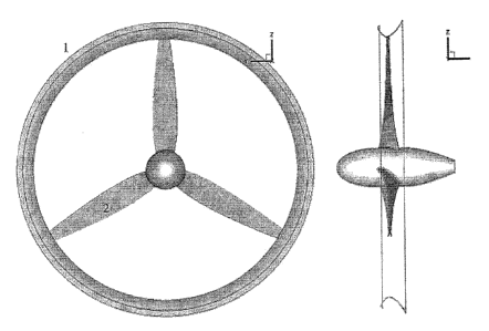
Figure I is a diagram of an aft and side view of a blade.
Figure 2 is a diagram of a perspective view of a blade.
Figure 3 is a diagram of blade cross-sections.
Figure 4 is a diagram of pitch.
DESCRIPTION OF THE PREFERRED EMBODIMENTS
The present invention is a new set of blade designs for shrouded turbines.
Definitions: For convenience, here are some common abbreviations used in the
claims
and the science of blade design, whether for water or wind turbines.
Chord length
C, Lift coefficient, C, = LITpVõ2c
C, Thrust coefficient, C, = TP2 vp s27R2
C Power coefficient, C,, = PõI4 pV1- R2
= Pressure coefficient, C,, = (p¨ pV,2
= Diameter, D =2R
Section camber
= Non-dimensional circulation, G = F 12R-RV,
Section offset
J, Advance ratio, is = Vs InD
K, Thrust coefficient, K, = T I pn2
CA 02752705 2015-08-10
FRIED104-ICA
6
Ko Torque coefficient, Ke =QI pn21;15
Rotational speed, rev/s
= Lift (per unit span)
= Pitch
= Delivered power
P, Vapor pressure
= Ambient pressure
Radial coordinate or radius of the propeller
= Propeller tip radius
Section thickness
= Thrust
= Torque
VI? Relative velocity
= Free steam speed
V. Tangential velocity
= Axial velocity
x, y,z Cartesian coordinate system (x + downstream, y + starboard, z + up)
çb Geometric pitch angle
= Circulation
= Fluid density
o- Cavitation number, cr = (pa,¨ p,)A 1,17,2
RPM Revolutions per minute, RPM = 60n
It is known by those familiar with the art of aerodynamics that Pitch (P) is a
linear
dimension while Phi is an angle. They are related by:
P = 2*pi*r*tan(Phi) or P/D = pi*(r/R)*tan(Phi)
where
r = local radius
R = tip radius
D = diameter = 2*R
Pitch (P) is the axial distance for one revolution of a cylindrical helix of
radius r.
CA 02752705 2015-08-10
FRI ED104-1CA
7
The principles and operation of a blade in a shrouded turbine according to the
present
invention may be better understood with reference to the drawings and the
accompanying
description.
Referring now to the drawings, Figure 1 illustrates an aft and side view of a
shroud
(1) and a blade (2) built according to the principles to be explained. The
specific type of
shroud shown here is a "Farb foil"¨defined in a previous patent. Figure 2 is a
perspective
view of the same structures. This section of the patent application
illustrates a 10-meter
diameter blade system (Radius R of 5 meters) combined with a Farb foil of 1
meter chord
length in water, but it can apply to many other configurations and fluids. One
can see a little
how the pitch at the periphery increases.
Figure 3 is a diagram of blade cross-sections from the blade discussed.
As shown in Figure 4, the pitch angle (Phi) (left vertical axis) of the
shrouded rotor
(4) relative to the open rotor (3) is about 2 degrees higher across much of
the span and
increases to about 13 degrees higher locally near the tip. The Phi of an open
rotor (3)
substantially decreases throughout. This difference is mainly due to the
increased axial flow,
particularly near the tip, that is induced by the shroud. At the same time,
the P/D ratio is
different for the shrouded (6) vs. open (5) rotor. Curve (4) reaches a minimum
at
approximately 82% of the distance to the periphery and then increases. In
contrast, the Phi
curve (3) of an open rotor always decreases. The P/D ratio of a shrouded rotor
(6) in this case
reaches a minimum at approximately 60% of the distance to the periphery, and
increases to
1.1 at the tip. By contrast, an open rotor design (5) always has a lower P/D
ratio at the tip
than at the root.
Blades were sized to keep the maximum lift coefficient less than 0.8 in the
design
condition. The turbine operating at 27 rpm in a 3 m/s (5.83 kt) stream was
predicted to
CA 02752705 2015-08-10
FR1ED104-1CA
8
produce a shaft power of 648 kW (869 hp). This estimate does not include
mechanical losses
in the hub.
This table (Table 1) reflects the design of the optimal blade for this
situation.
r/R c/D t/c f/c i6(deg) P/D c (m) t (m) f (m)
0.150 0.10490 0.18000 -0.03137 50.000 0.56160 1.049 0.189 -0.033
0.200 0.10450 0.17412 -0.04396 40.987 0.54593 1.045 0.182 -0.046
0.300 0.10249 0.16235 -0.05424 28.650 0.51493 1.025 0.166 -0.056
0.400 0.09908 0.15059 -0.05551 21.077 0.48431 0.991 0.149 -0.055
0.500 0.09411 0.13882 -0.05370 16.509 0.46555 0.941 0.131 -0.051
0.600 0.08724 0.12706 -0.05056 13.862 0.46514 0.872 0.111 -0.044
0.700 0.07829 0.11529 -0.04743 12.168 0.47418 0.783 0.090 -0.037
0.800 0.06764 0.10353 -0.04363 11.211 0.49814 0.676 0.070 -0.030
0.900 0.05554 0.09176 -0.03989 11.435 0.57193 0.555 0.051 -0.022
0.925 0.05230 0.08882 -0.03908 11.813 0.60780 0.523 0.046 -0.020
0.950 0.04896 0.08588 -0.03858 12.701 0.67266 0.490 0.042 -0.019
0.975 0.04553 0.08294 -0.03879 14.637 0.79998 0.455 0.038 -0.018
1.000 0.04196 0.08000 -0.04002 18.000 1.02077 0.420 0.034 -0.017
The following is a design for a smaller wind turbine surrounded by a partial
foil. It
shows the same principle of the Phi value increasing at the periphery. (Table
2)
r/R c/R Phi
0.13820 0.295890 44.95916
0.15596 0.286650 43.01705
0.18667 0.270180 39.76573
0.22496 0.250070 36.09830
0.26726 0.229480 32.10272
0.31156 0.210200 29.05061
0.35670 0.192960 26.41902
0.40198 0.177880 24.53083
0.44693 0.164780 22.56773
0.49122 0.153390 20.90665
0.53458 0.143480 19.51586
0.57680 0.134850 18.35955
0.61770 0.127330 17.38834
0.65711 0.120770 16.56282
0.69490 0.115050 15.84945
0.73092 0.110060 15.22573
0.76507 0.105690 14.70786
0.79723 0.101840 14.30656
0.82731 0.098452 14.00050
0.85520 0.095469 13.78477
CA 02752705 2015-08-10
FRIED104-1CA
9
0.88082 0.092852 13.64459
0.90411 0.090573 13.56008
0.92498 0.088608 13.51560
0.94338 0.086932 13.49927
0.95925 0.085530 13.49872
0.97254 0.084386 13.50525
0.98322 0.083488 13.51270
0.99126 0.082824 13.51756
0.99664 0.082387 13.52092
0.99933 0.082169 13.52319
The method of improving the percentage of power obtained from a shrouded
turbine
involves performing at least one and preferably two of the following
operations to create a
better match: changing the twist at the periphery and increasing the chord
length at the
periphery over what might have been done for an open blade. Designing the
blades with
characteristics obtained from the approximate midpoint of the normalized
velocity curve
enables one to take ideal advantage of the increased velocity without the risk
of stalling.
While the invention has been described with respect to a limited number of
embodiments, it will be appreciated that many variations, modifications and
other
applications of the invention may be made.