Note: Descriptions are shown in the official language in which they were submitted.
CA 02752748 2013-11-19
SELF REGULATING FLUID BEARING HIGH PRESSURE
ROTARY NOZZLE WITH BALAN = ED THRUST FORCE
BACKGROUND OF THE INVENTION
[0001] The present invention provides a simplifi:d and reliable construction
for a
high-pressure rotating water jet nozzle which is
rticularly well suited to industrial
uses where the operating parameters can be in t e range of 1,000 to 40,000
psi,
rotating speeds of 1000 rpm or more and flow rate. of 2 to 50 gpm. Under such
use
the size, construction, cost, durability and ease of maintenance for such
devices
present many problems. Combined length and di:meter of such devices may not
exceed a few inches. The more extreme operating =arameters and great reduction
in
size compound the problems. Pressure, temp: rature and wear factors affect
durability and ease of maintenance and attendant ost, inconvenience and safety
in
use of such devices. Use of small metal parts an. poor quality of materials in
such
devices may result in their deterioration or breakaie and related
malfunctioning and
jamming of small spray discharge orifices or he like. The present invention
addresses these issues by providing a simplified c=nstruction with a greatly
reduced
number of parts and a design in which net operating forces on nozzle
components
are minimized.
SUMMARY OF THE INVENTION
[0002] This invention provides a nozzle for use n a high pressure (HP) range
of
approximately 1,000 to 40,000 psi having a "straig t through" fluid path to a
jet head
at an end of the device where the head is prefer: bly capable of providing
rotating
coverage of greater than hemispherical extent, in = luding the area directly
along the
axis of rotation of the device. In a typical noz le assembly the internal
forces
resulting from such operating pressures tend to =reate an axial thrust force
acting
against the nozzle shaft with the force corresponding to the operating
pressure and
cross sectional area of the shaft. An example of a prior art device using
mechanical
bearings is shown in Applicants' prior U.S. Pat. N. 6,059,202. This prior art
device
provides the benefit that pressurized operating fl id can take a "straight
through"
from the inlet for the fluid source to the nozzle ead. However, in this device
the
rotating nozzle shaft is supported against the inte nal axial thrust forces by
a series
of stacked bearings, with plural bearings being uszd to bear the relatively
high thrust
1
CA 02752748 2013-11-19
load without increasing the diameter of the device In such devices the
mechanical
bearings have been used to serve as both radial ;nd thrust bearings, however
the
size and/or quantity of such bearings has been ictated primarily by the need
to
resist thrust forces.
[0003] It has generally been considered desira it le to keep the diameter of
any
rotating portions of a nozzle smaller than the larg.-st diameter of such a
nozzle so
that contact between the rotating portions and any surface being cleaned is
minimized or eliminated thereby minimizing ab asive wear to the nozzle and
interference with the rotational movement of the nozzle jets. Other prior art
devices
have used nozzles which rotate around a centr:1 tube which provides the fluid
source. However for the aforementioned reason, .uch devices, while being able
to
provide a cylindrical path of coverage with their ro ating bodies, have not
been well
adapted to both providing a rotating coverage whic can include a path very
close to
the rotational axis of the device and an "straight-through" fluid path.
[0004] In contrast to such prior art devices, th: device of the present
invention
provides a much simplified structure which also provides a straight-through
fluid path
in which the pressure of the operating fluid is al-o allowed to reach and act
upon
opposing surfaces of the rotating nozzle shaft so :s to effectively balance
any axial
thrust force. Further a small detachable jet head aving a diameter smaller
than the
body of the nozzle can be attached at the leadin end of the nozzle to provide
an
improved coverage pattern for the high-pressur- fluid. This is accomplished by
providing a "bleed hole" to allow a small portio of pressurized fluid to reach
a
chamber or channel within the housing but outsid: the exterior of the forward
portion
of the nozzle shaft where the fluid pressure can act upon the nozzle shaft
with a
sufficient axial component so as to balance th: corresponding axial component
against the nozzle shaft created by the internal fluid pressure. This chamber
or
channel communicates with the exterior of the de ice by means of a slightly
tapered
frusto-conical bore surrounding a corresponding apered portion of the shaft
which
further allows the fluid to flow between the body a d the shaft to facilitate
or lubricate
the shaft rotation.
[0005] Because of the tapered shape, the spa oing between the housing and the
shaft varies slightly with axial movement of the s aft and creates a "self
balancing"
effect in which the axial forces upon the shaft re am n balanced and there is
always
2
CA 02752748 2013-11-19
some fluid flowing between the shaft and housing hich helps decrease contact
and
resulting wear between these two components. I ue to the lack of any
significant
imbalanced radial forces and the fluid flowing betw-en the surfaces of the
shaft and
housing, a device of the present invention can =e constructed without need for
mechanical bearings.
[0006] In addition, around the inlet end of the sha an annular groove or
channel is
provided in the inside surface of the housing bod abutting the inlet end
portion of
the shaft. Surprisingly, this annular channel enhances bleed flow of fluid
around the
inlet end of the shaft to substantially reduce th- effects of rotationally
induced
precession on the shaft, thus improving the operability of the nozzle.
[0007] In one aspect, the present invention provid,- s a nozzle assembly for
rotatably
spraying high pressure fluid against an object to b: cleaned, the assembly
including:
a hollow housing body; a hollow tubular shaft m:mber coaxially carried within
the
housing body and captured between an inlet nut a d the housing body, the inlet
nut
having a stem forming an inlet bearing area on which an inlet end of the shaft
member is rotatably supported, the shaft member aving an outlet end near an
outlet
end of the housing body, the outlet end of the sha member configured to
receive a
spray head fastened thereto for rotation of the ss ray head with the shaft
member,
said shaft member and said inlet nut having a ce tral passage to conduct fluid
from
said inlet nut to said outlet end of said shaft mem ier; an inner wall of said
housing
body and a portion of said shaft member having complementary tapered surface
shapes, together forming a regulating passage t erebetween; said shaft member
having one or more bores communicating betwe -n the inlet bearing area and the
regulating passage , wherein pressure of fluid wi hin said regulating passage
acts
axially upon said shaft member (106) to counter axial force on said shaft
member
resulting from fluid pressure acting upon said inlet -nd of said shaft member.
[0008] In another aspect, the present inventio provides a nozzle assembly for
rotatably spraying high pressure fluid against an =bject to be cleaned, the
assembly
including: a spray head carried by a hollow cylindr cal housing body; a hollow
tubular
shaft member coaxially carried within the housing body between an inlet nut
and the
housing body for relative rotation between said shaft member and said housing
body, a stem on one of the inlet nut and the spra, head, said stem forming an
inlet
3
CA 02752748 2013-11-19
=
bearing area between the stem and the shaft me ber, said stem and said inlet
nut
having a central passage to conduct fluid from sa d inlet nut through said
stem to
said spray head; an inner wall of said housing 0 ody and a portion of said
shaft
member having complementary tapered surfa.e shapes, together forming a
regulating passage therebetween; said shaft me ber having one or more bores
communicating between the inlet bearing area an. the regulating passage,
wherein
pressure of fluid within said regulating passage ac s axially upon said shaft
member
to counter axial force on said shaft member resulti g from fluid pressure
acting upon
the housing body and the shaft member rotating re ative to each other.
[0009] The stem may be attached to or an integ : I extension of the inlet nut.
The
stem may be attached to or integral with the spray ead.
[0010] In another aspect, the present invention provides a nozzle assembly for
rotatably spraying high pressure fluid against an oiject to be cleaned, the
assembly
including: an inlet nut; a hollow cylindrical hou-ing body; a hollow tubular
shaft
member coaxially carried within the housing body .:nd captured between the
inlet nut
and the housing body; a spray head attached to one of the shaft member and the
housing body for rotation therewith; one of the inIzt nut and the spray head
having a
stem forming an inlet bearing area on which an inlet end of the shaft member
is
supported for relative rotation between the stem and the shaft member, the
shaft
member having an outlet end near an outlet ens of the housing body, said shaft
member, said stem and said inlet nut having a c.mmon central passage to
conduct
fluid from said inlet nut to said outlet end of said haft member; an inner
wall of said
housing body and a portion of said shaft memb-r having complementary shaped
surfaces together forming a regulating passage therebetween; said shaft member
having one or more bores communicating betw:en the inlet bearing area and the
regulating passage, wherein pressure of fluid w.thin said regulating passage
acts
axially upon said shaft member to counter axial force on said shaft resulting
from
fluid pressure acting upon said spray head.
[0011] The complementary shaped surfaces m.y be tapered. The stem may be
attached to or an integral extension of the inlet nu. The stem may be attached
to or
integral with the spray head. The housing body ay be attached to the spray
head.
The housing body may be attached to the inlet nu'.
4
CA 02752748 2013-11-19
DESCRIPTION OF THE DRAWINGS
[0012] FIG. 1 is a cross-section of the nozzle oft e preferred embodiment in
which
a tapered regulator passage also serves as a balancing chamber.
[0013] FIG. 2 is a cross-section of the nozzle of a alternative embodiment in
which
the balancing chamber is separate from the tapere= regulator passage.
[0014] FIG. 3 is a cross-section corresponding o FIG. 2 showing the shaft in a
slightly different axial position.
[0015] FIG. 4 is a cross-section of a structural va iation of the nozzle shown
in FIG.
1 in which an annular groove is provided in each of the bearing areas of the
nozzle
body.
[0016] FIG. 5 is a cross-sectional view of an. her embodiment of a nozzle in
accordance with the present invention.
[0017] FIG. 6 is a cross-sectional view of an.ther embodiment of a nozzle in
accordance with the present invention.
DETAILED DESCRIPTION OF THE INVENTION
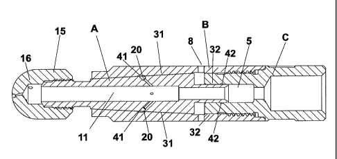
[0018] As can be seen most clearly in FIG. 2, one embodiment of the present
invention includes a simple three-piece rotary no. zle structure. A hollow
cylindrical
rotary shaft A is contained in a two part housing or body comprised of an
inlet portion
C and an outlet portion B. The housing portions are secured together and
sealed
using threading or other similar fastening mea s 2 which allows assembly and
disassembly of the device including allowing s aft A to be readily inserted or
removed. The inlet portion C provides an inlet 3 for high-pressure fluid fed
to the
device by hose or other similar means attached ti the inlet by any suitable
means,
most commonly a mated threaded fitting. A suita cle material for each of the
nozzle
portions will have fairly high strength and resista ce to galling, for
example, any of
various high nickel stainless steels. A bronze t bular shaft or bronze body
may
alternatively be used for enhanced galling resistan e. A surface treatment or
plating
may be used for any known benefits such as lubricity or abrasion resistance.
[0019] At the opposite end of the housing inlet portion is a cylindrical
cavity 5 which
receives the inlet end 6 of the rotating shaft A. T e annular interface 7
between the
housing and shaft is sized so as to minimize lea age while still allowing
rotation of
the shaft A with a slight cushion of fluid. Typicall the gap of the interface
7 will be
approximately 0.0025" to 0.0005". Some pass.ge of fluid at the interface 7 is
CA 02752748 2013-11-19
desirable in order to allow a fluid layer to facilitat- the rotating movement
between
the shaft A and outlet portion B. Elimination of t e need of a seal at
interface 7
reduces manufacturing expense and complexity n providing such a seal. Outlet
portion B is provided with radial "weep" holes 8 t. the exterior for escape of
fluid
passing the interface 7 or other paths along the extr nor of shaft A.
[0020] The shaft inlet 10 is open to the cavity 5 t. of provide direct flow of
fluid into
the central of bore 11 of the shaft A. Under norm,: I operation the
pressurized fluid
exerts an axial force on the inlet end 6 of shaft A hich will be referred to
herein as
the "input force." This force is directly proportional to (1) the area of the
inlet end 6
perpendicular to the direction of fluid flow and (2) he pressure of the fluid.
It is this
axial force which the present invention is intern, ed to counteract with an
equal
opposing force.
[0021] As the fluid enters the shaft most of the luid will pass through the
central
bore of the shaft to exit through the nozzle head 15 attached to the outlet
end 12 of
the shaft. Head 15 will typically be provided with :xit holes or orifices 16
positioned
to direct high pressure fluid toward a surface to b: cleaned and oriented to
impart a
reactive force to rotate the head and shaft.
[0022] A significant feature which eliminates the eed for dedicated thrust
bearings
is the provision of one or more passages or bore.. 20 which communicate
between
the central bore 11 of the shaft and a chamber 21 iefined between the outer
surface
of shaft A and the inner surface of the outlet po ion B and having an outlet
with
sufficient restriction to retain fluid pressure within t e chamber.
[0023] Passage or passages 20 are ideally confis ured to allow the pressurized
fluid
to reach chamber 21 with minimal restriction ts allow sufficient pressure to
be
achieved within chamber 21 so as to act upon the annular surface of the shaft
created by the stepped shoulder portion 22. A ternatively, for extreme
pressure
operation, e.g. operating in a range of 40,000 pi, passages 20 may be sized to
restrict the fluid pressure reaching the chamber 21. The stepped shoulder
portion 22
has a surface 23 which is directly perpendicula to the axis of the device.
Fluid
pressure acting upon this surface creates a thru.t force (which will be
designated
herein as the "resistive force") having a net axial component acting upon the
shaft
which is opposed to and capable of countering the input force described
previously.
6
CA 02752748 2013-11-19
[0024] In the embodiment shown in FIGS. 2 and suitable dimensions are a shaft
diameter .182" at inlet 10, an outer and inne diameters of .326" and .257"
respectively of chamber 21. The corresponding ngle of taper of both shaft and
housing along gap 30 is .57 degrees, with the hou.ing inner diameter tapering
from
.257" to .250" over the length of the taper.
[0025] In order that the input and resistive fsrces may remain balanced the
chamber or cavity 21 is provided with an outlet and regulator passage along
the path
defined by the narrow frusto/conical gap 30 between correspondingly shaped
portions of shaft A and outlet portion B. The taper:d configuration allows
variation in
the size of the gap as the shaft moves axially ith respect to the housing. For
example, the width of gap 30 may vary, being apprsximately .0001" as the shaft
A is
positioned toward the jet head shown in FIG. 3. A s the shaft moves to the
position
toward the inlet shown in FIG. 2, the width of gas 30 may open to
approximately
.001". A larger gap allows greater escape = pressurized fluid resulting in
corresponding decrease in the resistive force acti g upon the shaft.
Conversely, a
smaller gap allows an increase of pressure. Any imbalance between the input
and
resistive forces tends to cause some axial movem:nt of the shaft, which
increases or
reduces the gap in a manner which tends to rz-balance these opposing forces.
Accordingly, a state of equilibrium is reached wh- re the input and resistive
forces
remain dynamically balanced.
[0026] Another embodiment of the present invention is shown in FIG. 1 in which
the
functional features described are combined and orovided in a simplified
structure.
For there to be an axial resistive force it is unneces.ary that there be a
surface which
is actually perpendicular to the shaft axis as desc ibed above so long as
there is a
surface with an areal component which is effectiv-ly perpendicular to the
rotational
axis. In the simplified structure shown in FIG. 1 the port from the shaft bore
11
communicates directly with the tapered outlet pa.sage 31, which serves the
dual
function of being a balancing chamber or cavity, w ere a balancing resistive
force is
created and a regulator passage, to control the .mount of pressure which
creates
the resistive force. Since a force acting at any punt on the frusto-conical
surface
imparts both a radial force and an axial force, 'he total of such forces over
the
surface creates a net axial force and with no ne radial force. The following
table
illustrates suitable dimensions in inches for variou. parameters for flows
between 8
7
CA 02752748 2013-11-19
=
and 50 gallons per minute using the tapered =esign of one of the preferred
embodiments.
LOCATION Design Flow:
8 g = m 15 gpm 35 gpm 50 gpm
Inner diameter through tool O.0'6 0.150 0.240 0.300
(determines flow capacity)
(inlet end of shaft diameter) 0.1, 10 0.220 0.345
0.430
(largest shaft diameter) 0.3.50 0.506 0.750
0.840
(shaft diameter @ small end of taper) 0.2'30 0.375 0.560
0.560
(inlet inside diameter) 0.120 0.221 0.346
0.431
(body inside diameter- large end of taper) 0.3 '50 0.560 0.750 0.840
(body inside diameter- small end of taper) 0.2'35 0.376 0.561 0.561
(length of inlet end of shaft) 0.240 0.260 0.260 0.260
(length of taper) 0.750 1.242
[0027] Another embodiment is shown in FIG. 4. This figure shows a variation of
the nozzle structure of FIG. 1 in which identified el -ments are structurally
equivalent
and accordingly are correspondingly numbered. he annular groove 41 around the
tapered portion of outlet portion B facilitates distribution of the
pressurized fluid as it
exits the bores 20 in the shaft A into the tapere= outlet passage 31 between
the
frusto-conical tapered portions of the outlet po B
and the similarly tapered
portion of the shaft A.
[0028] Surprisingly, general functional characte istics of the structure of
FIG. 1
have been found to be unexpectedly enhanced b the addition of a
circumferential
annular groove, 15 channel or chamber 42 in the i side wall of the portion C
abutting
the inlet bearing area 32 of shaft A, as shown in Fl . 4. This channel or
chamber 42
provides a continuous unrestricted circumferential fluid circulation path
around the
shaft A in the inlet bearing area 32 between the rotting shaft A, and body
portion C.
8
CA 02752748 2013-11-19
Although inlet fluid is designed to weep axially pa%t the inlet bearing area
32 in the
embodiments shown in FIGS. 1-3, the presence of this groove in the embodiment
shown in FIG. 4 surprisingly improves shaft stabili y. It is believed that the
channel
42 may enhance circumferential distribution of th: small weepage flow around
the
shaft A passing through the bearing area 32 whic in turn minimizes the effects
of
precession of the shaft axis during operation. Th- result is a decreased, or
at least
maintenance of constancy of, the level of mec anical friction which may occur
between the relative movable parts and which wou d otherwise impede the
rotational
motion.
[0029] As shown in FIG. 4, this annular channel, or chamber 42, preferably has
a
generally rectangular cross sectional shape, although other shapes may result
in
similar performance. Optimally only a single chan el 42 is provided.
Preferably the
single channel 42 may have a width of between about .030 to about .050 inches
and
a depth of between about .020-.030 inches. Although the chamber 42 may
alternatively be formed in the outer surface of th. inlet end of the shaft A,
optimal
results appears to be achieved with the chamber 2 formed in the inlet bearing
area
32 of the housing portion C. The
annular groove 41 is created by a groove
machined into the inner surface of the outlet portion B. Alternatively, it is
believed
that a similar groove could be machined into the -xternal surface of shaft A
rather
than in the outlet portion B in order to achieve si ilar results. The groove
42 is an
annular channel having a substantially rectangular cross section. The groove
41 is
an annular channel having an arcuate cross section. The
cross sectional
configurations may be reversed between grooves 1 and 42 although a curved
cross
section of groove 41 is preferred in the tapered po ion of shaft A adjacent
the shaft
bore 20. Alternatively the grooves 41 and 42 m: y have different cross
sectional
shapes.
[0030] Another embodiment of a nozzle 100 is shown in FIG. 5. This nozzle 100
is
similar to nozzle 15 shown in FIG. 1 except that he total leakage rate
required to
balance the rotation of the nozzle 100 is reduced oy approximately a factor of
4. As
in FIG. 1, nozzle 100 as a body 102 fastened to a high pressure inlet nut 104.
The
inlet nut 104 is fastened to the body 102 via a ret. iner ring 103. Captured
between
the body 102 and the inlet nut 104 is a frusto-con cal shaft 106 rotatably
supported
on the stem 105 forming an inlet bearing area of th - inlet nut 104. A spray
head 107
9
CA 02752748 2013-11-19
is fastened to the shaft 106 so that both shaft 106 and head 107 rotate
together as
an integral unit. The inlet nut 104 and its inlet bea ing area, stem 105, has
a central
bore 111 that directs fluid flow into and through iorresponding spray bores in
the
head 107.
[0031] During operation, high pressure fluid is in Iroduced through the
central bore
111 in the inlet nut 104. This high pressure fluid 'asses out through the head
107.
A portion of the fluid flows around and along leakase path 110 along the inlet
bearing
area, i.e., the outside of the stem 105, through p.ssages or bores 108 in the
shaft
106 to the frusto-conical tapered interface betwee the body 102 and the shaft
106.
This fluid then diverges and flows outward in opp.site directions, first
forward along
leakage path 112 to exit the nozzle 100 around he head 107 and also rearward
along path 112 to the clearance space 113 betw:-en the inlet nut 104 and the
rear
face of the shaft 106. This portion of the fluid the passes through bores 114
in the
inlet nut 104 and past the retainer 103 to atmosphzre. As in the embodiment
shown
in FIG. 1, the shaft 106 becomes dynamically b: lanced on the stem 105 during
operation such that mechanical bearings are not r-quired. The lubricity of the
fluid
flowing through leak paths 110 and 112 sufficientl supports and lubricates the
shaft
106 and attached spray head 107. In this embodi ent, the leak path 110
generates
about a 90% drop in pressure by the time fluid pis to the passages 108 to
supply
fluid to the outer taper, i.e. leak paths 112. Thi allows a reduction of the
total
leakage rate by a factor of about 4 times.
[0032] A further alternative embodiment 200 of a nozzle in accordance with the
present invention is shown in FIG. 6. In this altern tive embodiment, the
spray head
210 and body 204 are attached together and rot. te about the shaft 206, which
is
fastened to the inlet nut 202. Nozzle 200 has the i let nut 202 fastened to
the frusto-
conical shaft 206 via threads 208. The body 2.4 has a complementary frusto-
conical shaped cavity that matches and interfaces with that of the shaft 206.
In this
embodiment, the stem 205 is attached, or an intrgral part of the spray head
210
rather than being an integral part of the inlet nut 212 as in nozzle 100.
Spray head
210 is secured also to the body 204 via split ring retainer 207 such that the
spray
head 210 and body 204 rotate as a single unit. W en nozzle 200 is assembled,
the
frusto-conical outer surface of the shaft 206 an. the frusto-conical inner
surface
portion of the body 204 form a tapered frusto-conic.:I leakage path 220.
CA 02752748 2013-11-19
[0033] During operation, high pressure fluid is in iroduced through the
central bore
211 through the inlet nut 202. This central bore 21 extends through stem 205.
This
high pressure fluid passes out through the head 010. A portion of the fluid
flows
around and along leakage path 212 along the inle bearing area, i.e., the
outside of
the stem 205, through passages or bores 218 in the shaft 206 to the interface
(regulating passage) between the frusto-conical t: pered portions of the body
204
and the shaft 206. This fluid then diverges and flo s outward in opposite
directions,
first forward along leakage path 220 to the clearan e space 213 and thence
through
bores 214 to atmosphere around the head 210 an* also rearward along path 220
to
atmosphere at the nut 202. As in the embodim- nts shown in FIGS. 1 and 4, the
body 204 and head 210 becomes dynamically bal:nced on the stem 205 within the
shaft 206 during operation such that mechanical bearings are not required. The
lubricity of the fluid flowing through leak paths 220 .round the interface 216
and path
212 along the stem 205 sufficiently supports a d lubricates the body 204 and
attached spray head 210 on the shaft 206. In th s embodiment, the leak path
212
generates about a 90% drop in pressure by the ime fluid gets to the passages
or
bores 218 to supply fluid to the outer taper, i.e leak paths 220. This allows
a
reduction of the total leakage rate by a factor of about 4 times as in the
nozzle 100.
[0034] Thus comparing embodiment 200 with e bodiment 100, it can be seen that
in both embodiments, the body and shaft rotate elative to each other. They
both
have complementary tapered surface shapes, together forming a regulating
passage, or leakage paths 112, 220 therebetwee . In nozzle 100, the shaft 106
is
fastened to the head 107 and rotates therewith. In nozzle 200, the shaft 206
is
fastened to the inlet nut 202 and held stationary, hile the body 204 is
fastened to
the spray head 210 and rotates around the statio ary shaft 206 via stem 205.
Note
that in nozzle 200 the stem 205 is integral with an. extends from the spray
head 210
rather than the nut 104 as in the nozzle 100. hus
in both embodiments of the
nozzle 100 and 200, the body 102, 204 and sha 106, 206 rotate relative to each
other and about the stem 105 and 205 respective y. In both nozzles 100 and
200,
inlet fluid flows through bore 111, 211 to the spr
head 107, 210, and fluid flows
from the inlet nut 104 and 202 into and through a irst leakage path 110, 212
around
the stem 105, 205 to bores 108, 218 between the shaft 106, 206 and the stem
105,
205, and then through the bores 108, 218 to the rusto-conical interface 216 of
the
11
CA 02752748 2013-11-19
body 102, 204. Fluid then diverges and flows :long the frusto-conical
interface
leakage paths 112, 220, i.e., the regulating pass:ge, in both embodiments out
to
atmosphere, adjacent the nut 104, 202 and throug bores 114, 214.
[0035] Thus comparing embodiment 200 with em sodiment 100, it can be seen that
in both embodiments, the body and shaft rotate re ative to each other and they
both
have complementary frusto-conical tapered surfac: shapes, together each
forming a
regulating passage, i.e., leakage paths 112, 220 herebetween. Pressure of
fluid
within the regulating passage in each embodiment acts axially upon the shaft
to
counter axial force on the shaft resulting from flui= pressure acting upon
said inlet
end of the shaft, thus dynamically balancing the r=tating parts without the
necessity
for mechanical bearings of any kind in the structure of the nozzle 100, 200.
[0036] In accordance with the features and ben:fits described herein, the
present
invention is intended to be defined by the claims b-low and their equivalents.
12