Note: Descriptions are shown in the official language in which they were submitted.
CA 02752792 2011-08-17
WO 2010/095134 PCT/IL2010/000143
-1-
METHODS AND SYSTEMS FOR DIAGNOSIS AND TREATMENT OF A
DEFINED CONDITION, AND METHODS FOR OPERATING SUCH SYSTEMS
FIELD OF THE INVENTION
This invention relates to methods and systems for diagnosing and/or treating a
defined condition in a subject, as well as methods for operating such systems.
BACKGROUND OF THE INVENTION
There are various methods and devices for improving health conditions of
humans without the use of medications.
When referring to traditional methods, one commonly used alternative medicine
concerns the traditional Chinese Medicine.(TCM). According to the concept
underling
TCM, illness and disease are a result of a blocked meridian. Acupuncture is
one tool
used to restore the flow of a chi, by inserting needles into acupuncture
points, located on
the meridians. Shiatsu makes use of pressure, stretching, rubbing and
corrective
exercises to restore chi flow. At times, Shiatsu applies pressure points onto
the body to
facilitate the long term pressure on a desired channel.
In the Western world therapies were developed including psychotherapy,
physiotherapy, reflexology biofeedback and neurobiofeedback, cognitive-
behavioral
therapy, social skills training, support groups, etc.
Devices and techniques have been developed to correct physiological as well as
psychological and cognitive states of patients.
U.S. Patent No. 5,963,294 describes therapeutic glasses for changing the
psychological state of a patient and a method for using the glasses. The
therapeutic
glasses include at least one lens of a size sufficient to cover an eye of the
patient. The
lens restricts vision to a lateral visual field.
CA 02752792 2011-08-17
WO 2010/095134 PCT/IL2010/000143
-2-
US Patent No. 6,610,081 describes methods and systems for the treatment of a
migraine headache and related maladies through filtering of portions of
ambient
transmitted to the eye of a patient.
US Patent No. 4,300,819 describes eyeglasses for use by color blind
individuals
or viewers, which are constructed to have two lenses, one of which is clear
and the other
of which is colored. Each lens formed to have a reflective or mirror surface
as viewed
from the front of the eyeglasses. When worn by a color blind viewer, the
combination of
lenses is described to improve the color blind viewer's ability to
discriminate between
different colored objects, while the reflective or mirror surfaces cause the
lenses to
appear to be identical to other persons or viewers.
US Patent No. 5,050,982 describes a method and apparatus for improving visual
acuity during sports activities.
SUMMARY OF THE INVENTION
The present invention provides, in accordance with a first of its aspects, a
method for improving a defined condition in a subject, comprising:
selecting a set of one or more correction zones, being surface zones on the
surface of the subject's skin or defined angular zones in the subject's field
of view, the
one or more correction zones being associated with the condition;
placing one or more correcting elements in said one or more correction zones
to
thereby cause improvement in said condition.
The invention also provides, in accordance with a second of its aspects, a
system
for improving a defined condition in a subject, comprising:
a management module comprising a database of defined conditions and
of correction zones associated with each of said conditions, the correction
zones being
surface zones on the surface of the subject's skin or defined angular zones in
the
subject's field of view;
- an input utility for inputting details of the subject's condition;
CA 02752792 2011-08-17
WO 2010/095134 PCT/IL2010/000143
-3-
- output utility for outputting a set of one or more correction zones
associated with the condition.
Further provided by an aspect of the present invention is a computer program
product comprising a computer useable medium having computer readable program
code embodied therein for performing a method of improving a defined condition
in a
subject, the computer program product comprising:
computer readable program code for causing the computer to select a set of one
or more correction zones, being surface zones on the surface of the subject's
skin or
defined angular zones in the subject's field of view, the one or more
correction zones
being associated with the condition; and
computer readable program code for causing the computer to outputting data
indicative of said selected correction zones, for allowing a user to place one
or more
correcting elements on the surface zone or in said angular zone of the
correction zones,
for improving said condition.
A further aspect of the present invention provides a kit for improving a
defined
condition in a subject comprising:
one or more correcting elements for application onto a selected set of one or
more correction zones;
instructions for applying said one or more correcting elements, the
instructions
comprising selecting a set of one or more correction zones being associated
with the
defined condition, the correction zones being surface zones on the surface of
the
subject's skin or defined angular zones in the subject's field of view (FOV).
In yet a further aspect of the invention there is disclosed a method of
providing a
correction zone related to a defined condition in a subject, comprising:
obtaining an input specifying a defined condition in the subject;
querying a first database using the specified defined condition to obtain a
correction zone associated with the specified defined condition, the
correction zone
CA 02752792 2011-08-17
WO 2010/095134 PCT/IL2010/000143
-4-
corresponding to a surface zone on a surface of the subject's skin or defined
angular
zones in the subject's field of view;
obtaining results indicating the subject's reaction to a test configured using
the
correction zone; and
contingent upon the subject's reaction to the selected correction zone meeting
a
predefined performance threshold, providing data with respect to the selected
correction
zone as output.
An additional method provided herein, in accordance with yet another aspect of
the invention is for providing a correction zone related to a defined cause,
in a subject,
associated with a defined condition, comprising:
obtaining an input specifying the defined condition;
querying a first database to determine a defined cause associated with the
specified defined condition;
querying a second database using the specified defined condition and the
defined
cause to obtain a correction zone associated with the specified defined
condition and the
defined cause, the correcting zone corresponding to a surface zone on a
surface of the
subject's skin or defined angular zones in the subject's field of view;
obtaining results indicating the subject's reaction to a test configured using
the
correction zone; and
contingent upon the subject's reaction to the selected correction zone meeting
a
predefined performance threshold, providing data with respect to the selected
correction
zone as output.
The invention also provides, in accordance with its additional aspect, a
system
for providing a correction zone related to a defined condition in a subject,
comprising:
an input interface for receiving input data specifying a defined condition in
the
subject;
a first database responsive to a query specifying the defined condition for
returning a respective correction zone associated with the specified defined
condition,
CA 02752792 2011-08-17
WO 2010/095134 PCT/IL2010/000143
-5-
the correction zone corresponding to a surface zone on a surface of the
subject's skin or
defined angular zones in the subject's field of view;
a testing configuration and management module adapted to obtain results
indicating the subject's reaction to a test configured using the correction
zone;
a test evaluation module adapted to determine whether the subject's reaction
to
the selected correction zone meets a predefined performance threshold; and
an output provisioning module adapted to provide as output data with respect
to
the selected correction zone.
Also disclosed herein is a system for providing a correction zone related to a
defined cause in a subject associated with a defined condition of the subject,
comprising:
an input interface for receiving an input specifying a defined condition;
a first database responsive to a query specifying the defined condition for
returning a defined cause associated with the specified defined condition;
a second database responsive to a query specifying and the defined cause for
returning a correction zone associated with the specified defined condition
and the
defined cause, the correcting zone corresponding to a surface zone on a
surface of the
subject's skin or defined angular zones in the subject's field of view;
a testing configuration and management module adapted to obtain an indication
regarding the subject's reaction to a test configured using the correction
zone; and
a test evaluation module adapted to determine whether the subject's reaction
to
the selected correction zone meets a predefined performance threshold; and
an output provisioning module adapted to provide as output data with respect
to
the selected correction zone.
In accordance with a yet a further aspect of the present invention, there is
provided a program storage device readable by machine, tangibly embodying a
program
of instructions executable by the machine to perform a method of providing a
correction
zone related to a defined condition in a subject, comprising:
CA 02752792 2011-08-17
WO 2010/095134 PCT/IL2010/000143
-6-
obtaining an input specifying a defined condition in the subject;
querying a first database using the specified defined condition to obtain a
correction zone associated with the specified defined condition, the
correction zone
corresponding to a surface zone on a surface of the subject's skin or defined
angular
zones in the subject's field of view;
obtaining results indicating the subject's reaction to a test configured using
the
correction zone; and
contingent upon the subject's reaction to the selected correction zone meeting
a
predefined performance threshold, providing data with respect to the selected
correction
zone as output.
In still a further aspect of the invention, there is provided a program
storage
device readable by machine, tangibly embodying a program of instructions
executable
by the machine to perform a method of providing a correction zone related to a
defined
cause in a subject associated with a defined condition in a subject,
comprising:
obtaining an input specifying a defined condition;
querying a first database to determine a defined cause associated with the
specified defined condition;
querying a second database using the specified defined condition and the
defined
cause to obtain a correction zone associated with the specified defined
condition and the
defined cause, the correcting zone corresponding to a surface zone on a
surface of the
subject's skin or defined angular zones in the subject's field of view;
obtaining results indicating the subject's reaction to a test configured using
the
correction zone; and
contingent upon the subject's reaction to the selected correction zone meeting
a
predefined performance threshold, providing data with respect to the selected
correction
zone as output.
CA 02752792 2011-08-17
WO 2010/095134 PCT/IL2010/000143
-7-
DESCRIPTION OF THE FIGURES
In order to understand the invention and to see how it may be carried out in
practice, embodiments will now be described, by way of non-limiting example
only,
with reference to the accompanying figures, in which:
Figures 1A and 1B are front view schematic illustrations of eyeglasses marked
with a polar coordinate system for placing correcting elements in accordance
with one
embodiment of the invention (Figure 1A) and some exemplary correcting elements
placed on eyeglasses based on the polar coordinate system (Figure 1B).
Figure 2 is a front view schematic illustration of a subject's skin on the
face
including some correcting elements placed in accordance with the Cartesian
coordinate
system, according to an embodiment of the invention.
Figure 3 is a block diagram illustration of a system for providing at least
one
correction zone related to a defined condition of a subject, according to some
embodiments of the invention.
Figure 4 is a flowchart illustration of a method of providing one or more
correction zones related to a defined condition in a subject, according to
some
embodiments of the invention.
Figure 5 is a block diagram illustration of a system for providing a
correction
zone related to a defined condition and possible defined causes in a subject
associated
with the defined condition, according to some embodiments of the invention.
Figure 6 is a flowchart illustration of a method of providing a correction
zone
related to a defined condition and possible defined causes in a subject
associated with
the condition, according to some embodiments of the invention.
Figures 7A-7C are integrated visual/auditory (IVA) continuous performance
test (CPT) results of a subject diagnosed as having ADD before using the
correction
glasses (Figures 7A) with the correction according to the method of the
invention
(Figure 7B) and after removing the correction glasses (Figure 7C), where RCQ
denotes Response Control Quotient, AQ denotes Attention Quotient, Pru denotes
CA 02752792 2011-08-17
WO 2010/095134 PCT/IL2010/000143
-8-
Prudence, CON denotes Consistency, STA denotes Stamina; VIG denotes Vigilance;
FOC denotes Focus and SPD denotes Speed.
DETAILED DESCRIPTION OF THE INVENTION
The present invention is based on the development of a unique map defining
correction zones, being surface zones on the surface of the subject's skin or
defined
angular zones, the surface zones and angular zones being in the subject's
field of view
(FOP), the one or more correction zones being associated with a condition.
This map
led to the development of a method of diagnosing and/or treatment, a system
and a
device for diagnosing and/or improving a subject's defined condition and a
method of
operating the system and the device.
Thus, in accordance with a first aspect, there is provided a method for
improving
a defined condition in a subject, comprising:
selecting a set of one or more correction zones, being surface zones on the
surface of the subject's skin or defined angular zones in the subject's field
of view
(FOV), the one or more correction zones being associated with the condition;
placing one or more correction element on said surface zones or in said
angular
zones to thereby cause improvement in said condition.
The invention also provides a method of applying one or more correction
elements on a set of correction zones being defined angular zones in the
subject's field
of view (FOV), the one or more correction zones being associated with the
condition;
and applying one or more correction element on said angular zones.
The invention also provides a kit for improving a defined condition in a
subject,
the kit comprising:
one or more correcting elements for setting on a selected set of one or
more correction zone;
instructions for setting said one or more correction elements on a
selected set of one or more correction zones, the correction zones being
surface
zones on the surface of the subject's skin or defined angular zones in the
CA 02752792 2011-08-17
WO 2010/095134 PCT/IL2010/000143
-9-
subject's field of view (FOV), the one or more correction zones being
associated
with the condition.
The selected set of one or more correction zones may be provided by a
physician, a practitioner or any other user of the system of the invention as
further
described below.
As used herein, the "defined condition" may be a subjective or objective
compliant that can be identified by the complaining subject (explaining what
the subject
is feeling), by a physician or a psychiatrist examining and diagnosing the
subject. When
referring to a subjective complaint it is to be understood to include a
condition that is
defined at least by the subject having the condition, even if cannot be
diagnosed or
identified by objective diagnostic tools as also discussed below. The
condition may be
selected from a condition related to the health or well being of the subject
and which
has been a priori diagnosed by a practitioner (a psychologist, a psychiatrist,
a
psychotherapist, a physiotherapist or a medical doctor) making use of
available tools,
such as psychological questionnaires DSM criteria (Diagnostic and Statistical
Manual
of Mental Disorders), or other evaluation/prognosis methods, diagnostic tools
such as
IVA (Integrated Visual and Auditory Continuous Performance Test), TOVA (Test
of
Variables of Attention), BRC (Brain Resource Cognition), CONNOR'S (Connor's
Rating Scale-asses), Attention Deficit Hyperactivity Disorder (ADHD)/
Attention
Deficit Disorder (ADD). Tests of vestibular system (balance) function include
electronystagmography (ENG), rotation tests, caloric reflex test,E43 and
computerized
dynamic posturography (CDP). Tests of auditory system (hearing) function
include
pure-tone audiometry, speech audiometry, acoustic-reflex, electrocochleography
(ECoG), otoacoustic emissions (OAE), and auditory brainstem response test
(ABR; also
known as BER, BSER, or BAER). Other diagnostic tests include magnetic
resonance
imaging (MRI) and computerized axial tomography (CAT or CT).
The condition may include, without being limited thereto, medical conditions
such as nausea, dizziness, motion sickness, vision and hearing problems,
epilepsy,
memory associated disorders psychological symptoms such anxiety, depression,
stress,
e.g. post traumatic stress disorders, compulsions, eating disorders,
addictions, attention
CA 02752792 2011-08-17
WO 2010/095134 PCT/IL2010/000143
-10-
deficit hyperactivity disorders, Skelton positioning (posture), motor
coordination,
energy level, lack of creativity, as well as a subjective or objective change
in the well
being of the subject.
In accordance with one embodiment of the invention, defining a subject's
condition is achieved using conventional diagnostic tools. In accordance with
another
embodiment, a condition is defined using a dedicated questionnaire. The
questionnaire
typically includes a series of specially designed questions, presented orally,
in writing,
graphically or by any other manners, allowing the stepwise gathering of
objective
information regarding the subject's condition. The questionnaire may lead to a
conclusion regarding the subject's condition or a substantiated assumption
regarding the
same.
Once the questionnaire is completed and a decision is made (either conclusion
or
assumption) regarding the subject's condition, a set of one or more correction
zones are
selected from a specially designed correction map defined by dedicated
coordinate
system. The coordinate system defines points or areas in the visual field of a
subject. As
will be described below, these correction zones are used to improve or correct
the
defined condition.
It is to be understood that in the context of the present disclosure, a
subject's
"visual field" or "field of view" or "FOV' denotes the full angular extent of
the area
visible to an eye that is fixating straight ahead at any given moment. Thus,
in the
context of the present invention, the correction zones, notwithstanding
whether they are
surface zones or angular zones, will always be within a subject's theoretical
visible area.
As used herein, the "coordinate system" that takes into consideration
distances
measured with respect to a subject's nose and eyes. The surrounding of the eye
may be
defined by axes and planes. As a reference vertical axis, a vertical line
passing through
the center of the nose divides a subject's field of view to two symmetrical
visual
hemifields (left and right). The "visual axis" is a straight line that passes
through the
apex of the cornea, the center of the pupil, and the thickest anterior-
posterior part of the
lens; the "horizontal plane" is defined to be the plane along which the visual
axis
sweeps when the eye turns around. The "horizontal plane" is common to the left
and
CA 02752792 2011-08-17
WO 2010/095134 PCT/IL2010/000143
-11-
right eye and encompass the line connecting between the centers of a subject's
eyes,
when the eyes are fixated straight ahead ("horizontal line" (HL)). The
coordinate
system is divided into a left (L) coordinate system and a right (R),
coordinate system.
The left or right coordinate systems may be a polar coordinate system or a
Cartesian coordinate system as well as any other type of coordinate system.
As appreciated, a polar coordinate system is a two dimensional coordinate
system in which a point (i) is determined by an angular coordinate (0i, also
known as
the polar angle or the azimuth angle) and a radial coordinate (ri). In the
context of the
present disclosure, the radial coordinate denotes the point's distance from
the optical
center (OC), i.e. the center of the pupil when the eye is fixating straight
ahead, the
angular coordinate denotes the positive or anticlockwise angle required to
reach the
point from the 0 ray, defined by the horizontal line or the polar axis
(equivalent to a
positive X-axis in the Cartesian coordinate plane).
The coordinate system may alternatively include a Cartesian coordinate plane,
defined by the horizontal line (equivalent to the x-axis) and a vertical line
being
perpendicular to the horizontal line and positioned along the longitudinal
length of the
nasal bone (long axis of the nasal bone, aligned on the center of the nasal
bone). To this
end, the point (i) is defined by an x and y values (x,y). The use of a
Cartesian coordinate
system is further discussed below.
The correction map includes coordinates for numerous correction zones. The
correction zone may be a surface zone or an angular zone. As used herein, the
term
"surface zone" denotes a location on the surface of the subject's skin within
his or her
FOV. The surface zone may include an area on the subject's nose, cheek,
eyebrow,
eyelid, etc., on the subject's face. Being an area on the subject's face, it
is to be
understood that the zone is fixed in place, keeping throughout time its
coordinates. The
term "angular zone" denotes a location fixed with respect to the subject's
left or right
coordinate system, and being within the subjects FOV. It is noted that while
the
correction zone is within the subject's FOV, it does not necessarily mean that
the subject
has vision in all the FOV. In other words, the invention also applies to
subjects having
either temporary or permanent impaired vision. Each condition improved by the
method
CA 02752792 2011-08-17
WO 2010/095134 PCT/IL2010/000143
-12-
disclosed herein may be associates with a one or more correction zones and a
correction
zone may be related to one or more defined conditions. In other words, for
improving a
condition, one or more correction zones may be of significance and the
correction zone
may include only surface zones, only angular zones or a combination of one or
more
surface zones with one or more angular zones.
Table 1 and Figures IA-1B provide some exemplary correction zones making
use of a polar coordinate system to be placed on a subject's eyeglasses or any
other
object as discussed below. Some of the zones included in Table 1 are also
illustrated in
Figure 1.
Table 1: Exemplary angular zones, to be placed on the subject's eyeglasses,
using polar
coordinate system
Angular zone (3 R(mm) Condition to be improved
on glasses (1)
18L 143 25 Migraine
18R 37 25 Migraine
19L 109 12 Depth perception
19R 71 12 Depth perception
20L 171 20 Posture- Balance & stability
20R 9 20 Posture -Balance & stability
21L 117 13 Fatigue
21R 63 13 Fatigue
22L 162 22 Anxiety
22R 18 22 Anxiety
23L 196 16 Atopic dermatitis
23R 344 16 Atopic dermatitis
24L 45 10 Eyestrain
CA 02752792 2011-08-17
WO 2010/095134 PCT/IL2010/000143
-13-
Angular zone R(mm) Condition to be improved
on glasses (1)
24R 135 10 Eyestrain
25L 300 15 Speech impediment &Stutter
25R 240 15 Speech impediment &Stutter
26L 193 19 Epilepsy
26R 347 19 Epilepsy
27L 40 22 Difficulty in balancing hearing in noisy
environment
27R 140 22 Difficulty in balancing hearing in noisy
environment
28L 140 24 Balancing note rhythm - reading music
28R Balancing note rhythm - reading music
29L 150 14 Double vision
29R 235 14 Double vision
30L 040 17 Difficulty in focusing while reading
30R 140 70 Difficulty in focusing while reading
31L 360 18 Difficulty in focusing while reading English
31R 180 18 Difficulty in focusing while reading Hebrew
32L 045 14 Dizziness and motion sickness
32R 135 14 Dizziness and motion sickness
33L 110 15 General restlessness as result of emotional and
physical condition
33R 070 15 General restlessness as result of emotional and
physical condition and memory difficulties
34L 150 21 Eyesight and hearing balancing
CA 02752792 2011-08-17
WO 2010/095134 PCT/IL2010/000143
-14-
Angular zone R(mm) (3) Condition to be improved
on glasses (1)
34R 030 21 Eyesight and hearing balancing
35L 190 21 Equilibrium, nausea and respiratory focus
35R 350 21 Equilibrium, nausea and respiratory focus
- -- -- - . _._... --- --- -- - - -~.._..- - - - ...._._...... ..... .......
....... -.......
- 36L 200 19 Appetite balancing
36R 340 19 Appetite balancing
37L 165 24 Lack of visual balance as a result of difference
in visual performance between eyes
37R 015 24 Lack of visual balance as a result of difference
in visual performance between eyes
38L 185 22 Difficulty in focusing while reading from left to
right
38R 355 22 Difficulty in focusing while reading from left to
right
39L 045 19 Difficulty in focusing while reading a language
read downwardly
39R 135 19 Difficulty in focusing while reading a language
read downwardly
40L 310 18 Difficulty in focusing while reading a language
read downwardly, the difficulty being mainly at
the bottom end of the text
40R 230 18 Difficulty in focusing while reading a language
read downwardly, the difficulty being
concentrated at the bottom end of the text
I- -j L
"L" designates left side of the face, "R" designates right side of the face
(2),(3) the acceptable deviation for the indicated angle and radium is
respectively 5 and
5mm, although in some cases it may be greater.
CA 02752792 2011-08-17
WO 2010/095134 PCT/IL2010/000143
- 15-
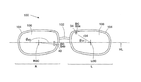
Figure 1A schematically illustrates the construction of a right (R) and left
(L)
polar coordinate system on a subject's eyeglasses (100) in accordance with one
embodiment of the invention. The eyeglasses comprise a left eyepiece (L) and a
right
eyepiece (R) and a arch 102 connecting there between. Each eyepiece consists
of a
frame 104 and a lens 106. In addition, each eyepiece has a respective optical
center,
namely a left optical center (LOC) and a right optical center (ROC). Each
optical
center constitutes the origin of the respective left (L) and right (R)
coordinate system,
i.e. from which the angular coordinate 0i and the radial coordinate ri are
measured. The
LOC and ROC are connected by the horizontal line HL. Figure 1 also illustrates
two
correcting elements, 34, defined by coordinates (6)34=150 , r34=21mm) and 40,
defined
by coordinates (640=310 , r40=18mm. Both correcting elements 34L and 40R have
a
rectangle shape. The rectangle shape may be defined by a diagonal Di, and in
this
particular embodiment, the diagonal of correcting element 34, D34, is shorter
than the
diagonal D40, for correcting element 40. The center of diagonal D40, Dc, is
disposed at
the center of the respective correction zone.
Figure 113 provides the positioning of correcting elements making use, in this
non-limiting embodiment, of a polar coordinate system (correcting elements
being listed
in Table 1). For simplicity, like reference numerals to those used in Figure
1A, shifted
by 100 are used to identify components having a similar function. For example,
component 102 in Figure 1A is an arch having the same function as arch 202 in
Figure 1B
As indicated above, coordinate systems other than the polar coordinate system
may equally be applicable, and this includes also the Cartesian coordinate
system
mentioned above, where the point (1) is defined by the x coordinate,
represented by the
horizontal line, and the y coordinate, represented by the longitudinal axis of
the nasal
bone, being perpendicular to the horizontal line.
Table 2 and Figure 2 provide some exemplary correction zones making use of a
Cartesian coordinate system to be placed on a subject's skin, where point (0,0
is the
intersection between the horizontal line and the vertical line (longitudinal
nasal axis).
CA 02752792 2011-08-17
WO 2010/095134 PCT/IL2010/000143
-16-
Table 2: Exemplary surface zones to be placed on a subject's skin for defined
conditions using a Cartesian coordinate system
Surface X (mm) Y (mm) Condition to be improved
zones
41L 17 9 Lack of focus, restlessness, lack of assertiveness
41R -17 9 Lack of focus, restlessness, lack of assertiveness
42L 10 6 Emotional stress
42R -10 6 Emotional stress
43L 7 5.5 Restlessness and predisposition for negative moods
43R -7 5.5 Restlessness and predisposition for negative moods
44L 6 -10.5 Nausea
44R -6 -10.5 Nausea
45L 2 -5 Asthmatic symptoms
45R -2 -5 Asthmatic symptoms
46L 0 9 Headaches
46R 0 9 Headaches
47L 10 6 Migraine
47R -10 6 Migraine
48L 5 14 Hearing balance in noisy environment
48R -5 14 Hearing balance in noisy. environment
49L 3 2 General focusing and stability
49R -3 2 General focusing and stability
50L 6 -4 Dizziness
50R -6 -4 Dizziness
51L 0 -5 Sinus relief
CA 02752792 2011-08-17
WO 2010/095134 PCT/IL2010/000143
-17-
Surface X (mm) Y (mm) Condition to be improved
zones
51R --- 0 --- -5 --- Sinus relief
52L 7 5 Appetite balancing
52R -7 5 Appetite balancing
53L 2 3 Epilepsy ------------...__-----
--- --........ ......... -. -........ . _....... --.................
- - - - -- -
53R -2 3 Epilepsy
54L 4 6 Depth perception
54R -4 6 Depth perception
(1)"L" designates left side of the face, "R" designates right side of the face
(2),(3) the acceptable deviation for the indicated value being 5 for each
coordinate
Reference is now made to Figure 2 schematically illustrating a human subject's
skin comprising the surface of the nose 300, a horizontal line X, connecting
the left
optical center (LOC) with the right optical center (ROC), and a vertical line
Y, being
perpendicular to the horizontal line X. Various correcting elements (listed in
Table 2)
are placed on the skin surface of the illustrated nose making use of the
Cartesian
Coordinate system. To this end, line X represents an x axis in the coordinate
system and
line Y represents the y axis in the coordinate system. Each correcting element
being
placed such that the correcting element overlaps with the x,y coordinate
representing the
correction zone.
As evident from the exemplary correction zones listed in Tables 1 and 2, each
condition may be improved by placing one or more correcting elements in a
predetermined correction zone.
It is noted that the method of the present disclosure provides improvement in
a
subject's defined condition that may be a qualitative improvement (objective
or
subjective improvement, as will be explained below) as well as a quantitative
improvement.
CA 02752792 2011-08-17
WO 2010/095134 PCT/IL2010/000143
- 18-
The qualitative improvement may includes any change in the subject's well
being as observed by the subject or his surroundings, such as the improvement
in
focusing, relaxation, controlled activity (in case of hyperactive subjects),
amelioration
of symptoms associated with dizziness, restlessness, nausea, asthma, a more
energetic
feeling of the subject etc.; the quantitative improvement may include
measurable
parameters available to the practitioner, such as to a psychologist,
psychiatric, or other
medical practitioner as well as to the patient himself, for example, the
patient
experiencing a time-wise improvement in his ability to sit and focus while
doing a task
that otherwise would not be possible (time being the measurable parameter).
The
measurable parameter may be provided by diagnostic tools outputting a
parameter or
value indicative of a condition. For example, Integrated Visual/Auditory (IVA)
continuous performance test is well established as a quantitative tool
allowing the
clinician diagnose and differentiate between six sub-types of Attention-
Deficit/Hyperactivity Disorder (ADD/ADHD) based on neurophysiologic measure of
attention.
The improvement may include partial amelioration of a defined condition as
well as complete alleviation. It is to be understood that partial amelioration
includes any
exhibited change in a condition, even if the condition still exists. In
quantitative terms,
when applicable, the partial improvement may include from 5, 10, 20, 30, 40,
50, 60,
70, 80, 90, 95 and even 98% improvement or that has otherwise shown to be
significant.
The improvement may be determined by subjective parameters, e.g. the
subjective
feeling of the subject treated, an evaluation by a second party, e.g. a
physician, as well
as by quantitative parameters obtained by the use of conventional assessment
tools, such
as the IVA described above.
The improvement is typically maintained as long as the one or more correcting
elements are maintained in place. In this connection, it is noted that the
treatment may
be modular, i.e. the treatment may include one or more sessions having time
intervals
therebetween of several minutes, hours, days, weeks, months and more, each
session
comprising re-defining the condition and assigning the re-defined condition
with a set
CA 02752792 2011-08-17
WO 2010/095134 PCT/IL2010/000143
-19-
of correction zones, the set including one or more of such correction zone and
then
fitting the subject with a corresponding set of correcting elements.
To achieve improvement in a defined condition, one or more correcting
elements, are fixed on the surface zone and/or in the angular zone. The
correcting
elements are typically placed such that their center essentially overlaps with
the center
of the correction zone, although some deviation from this alignment may take
place. In
this connection it is also noted that two or more correcting elements may
overlap each
other to form a continuous stretch of correcting elements, e.g. to form a long
rectangular
element.
The correcting/correction element may be any type of a mark in the correction
zone. The mark may be in the form of a sticker, tattoo, filtering means, light
beam or the
like placed on the subject's skin or a sticker, etch, color or opaque mark
etc. placed on
the subject's eyeglasses. The mark may be of variable shapes, size, material,
texture,
dimension, color and, contour. The mark may even be a precious stone, such as
a
diamond, or any other material placed at the one or more correction zones. The
correcting element may have a defined geometrical shape, e.g. a polygon or a
circular
shape, which may be symmetrical or unsymmetrical or the correcting element may
have
an irregular shape. When the correcting element has the shape of a square or a
circle, the
length of the, respectively, diagonal or diameter will be in the range of
between several
millimeters and up to several centimeters; for other polygons or for an
ellipse, the
longer diagonal, or respective major axis as well as the shorter diagonal, or
respective
minor axis will be in the range of from about several millimeters to about
several
centimeters.
In one embodiment, the correcting element is a mark, such as a sticker to be
placed on a subject's eyeglasses (on the frame, on the lens etc.) or on the
subject's facial
surface (surface zone). In another embodiment, the correcting element includes
etching
or coloring one or both lens. The correcting element may be a colored, opaque
as well
as transparent, translucent and may differ in shades and colors.
While the foregoing and below description refers to eyeglasses, it is noted
that
the method disclosed herein may equally be implemented with the one or more
CA 02752792 2011-08-17
WO 2010/095134 PCT/IL2010/000143
-20-
correcting elements being placed on or embedded in or displayed on a pince-nez
(eyeglasses without the earpiece); a monocle, sunglass, zero glasses, eye wear
viewers
or other transparent or partially transparent display on glasses such as LCD,
OLED
glasses and the like.
In the above description, a system, a computer program product, and a method
of improving a defined condition in a subject were described. There is now
provided in
accordance with a further aspect of the invention, a description of a system,
a computer
program product, and a method of providing one or a set of correction zones
related to a
defined condition in a subject. Reference is now made to FIG. 3, which is a
block
diagram illustration of a system for providing at least one correction zone
related to a
defined condition of a subject, according to some embodiments of the
invention.
Accordingly, the system for providing a correction zone related to a defined
condition in a subject 300 may include an input interface 310, a Correction
Zone
database 320, a testing configuration and management module 330, a test
evaluation
module 335 and an output provisioning module 340.
The input interface 310 may be adapted to obtain or receive data with respect
to
a subject's defined condition or conditions. As described in detail above, the
term
"defined condition" as used herein may relate to a subjective or objective
compliant of
the subject. The data with respect to the defined condition may be
automatically
extracted from a pre-stored digital data source, such as a structured file
(e.g., a form
including content and metadata) or it may be manually input by an
operator/user of the
system 300.
The data with respect to the defined condition may be locally fed to the
system
300, for example, through a keyboard directly connected to the system 300 ("on
site"),
or the data with respect to the defined condition may be obtained from a
remote
location, for example, from a remote computer operatively connected to the
system 300
over a communication network, for example, the World Wide Web (WWW). In some
embodiments, the system 300 may obtain further information related to the
subject and
or the subject's defined condition, as will be described in further detail
below.
CA 02752792 2011-08-17
WO 2010/095134 PCT/IL2010/000143
-21-
In some embodiments, the subject's defined condition is provided to or
obtained
by the system 300 as input and is not independently generated by the system
300. In
one non-limiting example, a condition may be defined using a dedicated
questionnaire
302. The questionnaire 302 typically includes a series of specially designed
questions,
presented in writing, orally, graphically or in any other manner. The
questionnaire 302
may allow a stepwise gathering of objective information regarding the
subject's
condition. The questionnaire 302 may lead to a conclusion regarding the
subject's
defined condition or a substantiated assumption regarding the same, as well
as, or
alternatively, information regarding one or more defined causes of a condition
or the
subject's complaint. In the context of the invention, the term "defined cause"
is used
herein to denote any physiological, psychological, environmental etc. cause of
a defined
condition as detailed above, whether a priori known to be associated with the
defined
condition or not. In accordance with a further non-limiting example, defining
a subject's
condition may be achieved using conventional diagnostic tools. As an example,
in FIG.
3 a computer based diagnosis system 304 is shown. The computer based diagnosis
system 304 may be operatively connected to the system 300 and may provide as
input a
subject's condition.
In further embodiments of the invention, the system 300 may include a defined
condition resolution module 315. The defined condition resolution. module 315
may be
adapted to receive input associated with a defined condition but, which do not
indicate a
specific condition as such, and the resolution module 315 may be configured to
look up
or otherwise determine a best-match from among an entire set of defined
conditions (or
some part thereof) based on the information provided as input with respect to
the
subject's condition.
By way of example, and according to some embodiments, the defined condition
resolution module 315 may include a Keywords database 317. The Keywords
database
317 may provide for each defined condition listed therein a list of associated
keywords.
In case the input to the system 300 is not conclusive regarding the subject's
defined
condition, the defined condition resolution module 315 may be configured to
obtain
keywords from the input data relating to the subject's condition and to
determine a score
CA 02752792 2011-08-17
WO 2010/095134 PCT/IL2010/000143
-22-
for each (or for some) of the defined conditions in the Keywords database 317.
Various
scoring schemes for scoring a correlation between input information and a
database
entry according to keywords listed in the entry are known and may be used as
part of
some embodiments of the present invention. It would be appreciated that one or
more
defined conditions may be selected. The handling of multiple (two or more)
defined
conditions in a subject shall be described below.
Reference is now additionally made to FIG. 4, which is a flowchart
illustration
of a method of providing one or more correction zones related to a defined
condition in
a subject, according to some embodiments of the invention. Initially, an input
specifying a subject's defined condition is provided (block 405). The testing
configuration and management module 330 is responsive to the input specifying
the
subject's defined condition to query the Correction Zone database 320 using
the
specified condition to determine an associated initial correction zone (block
410). As
mentioned above, the present invention is based on the development of a unique
map
defining correction zones. Each one of the correction zones is associated with
at least
one defined condition, which is also defined above. The correction zones
represent
surface zones on the surface of a subject's skin or defined angular zones. The
surface
zones and angular zones are in the subject's field of view (FOY). The terms
"surface
zones", "angular zones", "visual field", "field of view", "FOV' are described
in further
detail above. A "coordinate system" may be provided and each one of the
correction
zones may be denoted by coordinate(s) on the coordinate system. The term
"coordinate
system" is described in further detail above. Table 1 and Figures 1A-1B
provide some
exemplary correction zones making use of a polar coordinate system. Table 2
and
Figure 2 provide some exemplary correction zones making use of a Cartesian
coordinate system.
In some embodiments, the initial correction zones in the Correction Zone
database 320 are taken from or otherwise based upon a map such as that
provided above
in Table 1 and in Table 2, according to the respective condition. In further
embodiments, the initial correction zones are taken from any other source
which defines
the relation between one or more correction zone and a defined condition. In
still
CA 02752792 2011-08-17
WO 2010/095134 PCT/IL2010/000143
-23-
farther embodiments, while a map such as that provided above in Table 1 or in
Table 2
is used as a source of the correction zones data and specifies the relation
between each
defined condition supported by the system and its respective initial
correction zone, the
tables and/or the corresponding Correction Zone database 320 implemented by
the
system 300 may be updated from time to time. The updates to the Correction
Zone
database 320 may include adding, removing or modifying the list of defined
conditions
and/or adding, removing or modifying a correction zone for a certain defined
condition.
Once initial correction zones are obtained, the testing configuration and
management module 330 may be adapted to configure a test using the specified
condition and the correction zone (block 415). As will be explained below, the
correction zone that is used by the system 300 in conjunction with the
subject's defined
condition may change during the process implemented by the system 300, and
thus the
configuration of the test may change at different iterations of the process
shown in FIG.
4.
In some embodiments, the system 300 may include or may be associated with a
plurality of test programs. In some embodiments, the test program or the
series of test
programs to be used may be selected based on the specified defined condition
and/or
based on the correction zone and/or based on the progress of the process
implemented
by the system 300. In yet further embodiments, the system 300 may be
implemented
with a predefined test program that is used for all conditions and is only
configured as
necessary. In case a test program is used by or in conjunction with the system
300,
block 415 is implemented on the selected test program, whichever method and
parameters are used for the selection thereof, including in case when a single
predefined
test program is used. It would be appreciated however that further embodiments
of the
invention, are not limited to a system 300 which includes a test program, and
such
embodiments are not limited by the manner in which the test is implemented.
For
convenience, embodiments of the present invention are described below with the
use of
a test program.
For illustration, a non-limiting example of a test program that is associated
with
the defined condition 'dizziness' is now provided. Dizziness is a defined
condition of
CA 02752792 2011-08-17
WO 2010/095134 PCT/IL2010/000143
-24-
the subject that may be determined as mentioned above in various ways. For
example,
this information may be provided to the system 300 through a digital
questioner 302.
The initial correction zone for dizziness is thus obtained and a set of
performance tests
configured for the dizziness condition may be presented to the subject. By way
of
example, initially the dizziness performance tests may be presented to the
user without
using an actual or a simulated correcting element which corresponds to the
current
correction zone. A severity of the defined condition referred to as
'dizziness' is then
defined, for example, based on the results of the initial test(s) and possibly
also by
obtaining a subjective input from the subject in this regard. In the next
stage of the test,
a correcting element associated with the current correction zone for
'dizziness' is placed,
for example, on the subject's glasses. The correcting element(s) may be
otherwise
presented into the subject's FOV. For example, the correcting element(s) may
be
simulated on a computer screen that the subject is looking at. In another
example, the
correcting element is simulated on digital glasses which include an OLED or
LCD
transparent or semi-transparent display used as the lenses of the digital
glasses. As will
be explained below, the correction zone suggested by the system 300 for a
given
defined condition may change as the process implemented by the system 300
progresses, and so the correcting element presented into the subject's FOV
during tests
may also change accordingly.
Continuing with the description of the test that is associated with the
defined
condition 'dizziness', once the correcting element is in place, the subject is
presented
with a set of performance tests according to his state of dizziness, possibly,
but not
necessarily, the same tests that were used without any correcting element may
be
repeated, this time with the correcting element in place. The subject's
performance may
be evaluated and some score or other descriptive data may be generated.
Possibly a
subjective evaluation may also be provided based on the subject's subjective
feedback.
In some embodiments, as the process progresses and the correction zone and the
corresponding corrective element are fine tuned, as will be described below,
the
difficulty of the tests applied or presented to the subject may gradually
increase.
CA 02752792 2011-08-17
WO 2010/095134 PCT/IL2010/000143
-25-
Each one of the tests used by the system 300 may be carried out on a test
platform. By way of example, the system 300 shown in FIG. 3 is operatively
connected
to a computerized test platform 352 a mobile computerized platform 353 and a
wearable
test platform including a transparent OLED (or LCD) display 354 (glasses-
like). When
a test is selected, the associated test program may be downloaded to the test
platform (if
not already available on the test platform) and the test program may be
initiated
according to the test specification and the test configurations. Some of the
test
configurations necessary for carrying-out the test on the test platform may be
included
in the test specification and may be used by the testing configuration and
management
module 330 to configure the test program so that it is suitable for running on
the test
platform (block 420).
According to further embodiments, optionally the testing configuration and
management module 330 may also be adapted to configure the test according to
the
subject's personal information. According to some embodiments, the subject's
personal
information may include, but is not limited to, one or more of the following:
parameters
relating to the subject's facial anatomy, e.g. distance between the subjects
eyes (as
commonly measured when prescribing a subject with eyeglasses), geometry and
dimensions of the subject's spectacles or other eyewear, information regarding
age, sex,
etc. of the subject. For example, for a person suffering from eyesight
impairment (but
that is not the condition for which that person is interacting with the
system), the system
may adapt the benchmark of tests where eyesight is a factor accordingly.
Optionally, as part of some embodiments, once all configurations are complete
the test is run (block 425). A possible test scenario was provided above with
respect to
the defined condition 'dizziness'. It would be appreciated that the tests
themselves may
be implemented outside the system 300, for example on the computerized test
platform
352. In other embodiments, the test platform is an integral part of the system
300 and
the testing procedure is implemented as part of the method of providing a
correction
zone related to a defined condition in a subject.
Data with respect to the test results and/or with respect to the subject's
performance during the test may be obtained (block 430). For example, for
certain
CA 02752792 2011-08-17
WO 2010/095134 PCT/IL2010/000143
-26-
defined condition(s) the integrated visual/auditory (IVA) continuous
performance test
(CPT) described below may be presented to the subject and the score result may
be
obtained by the system 300. The test results data may include objective
feedback, such
as test scores, subjective feedback from the subject. The feedback may be
independent
or may be relative to other tests and/or previous results. For example, the
test results
may measure a change in the performance of the same test with and without the
(simulated) correcting element. Various physical sensors may also be used
during the
tests to measure various physical reactions in.the subject to the test, in a
manner know
per se. Examples of sensors include, but are not limited to BLOOD PRESSURE
SENSOR, HAND DYNAMOMETER SENSOR, RESPIRATION MONITOR BELT, STRESS
THERMOMETER, GALVANIC SKIN RESPONSE (GSR) sensors.
The test evaluation engine 335 may parse and format the test results as
necessary, and then process the test results to determine a deviation from a
benchmark
associated with the test(s) (block 435). In some embodiments, the benchmark
may be
associated with the current correction zone and/or with the defined condition
and/or
with the progress of the process implemented by the system 300. For
illustration, in the
IVA test example described below, for a certain defined condition the
benchmark may
be equivalent to an IVA score of 100.
Once the test results are processed, and the deviation from the benchmark is
determined, the test evaluation engine 335 may be configured to determine
whether the
performance meet a predefined threshold (block 440). In some embodiments, the
predefined threshold represents a result that is considered a minimal
significant-result
that the subject would need to achieve in order for the system 300 to suggest
the
respective correction zone for improving the defined condition. Accordingly,
in case
the threshold is met, the system 300 provides as output a specification of a
selected
correction zone or a set of correction zones. In some embodiments, and as is
shown in
FIG. 4, the system 300 may utilize the output provisioning module 340 to
provide as
output a correcting element(s) corresponding to the selected correction
zone(s) (block
445).
CA 02752792 2011-08-17
WO 2010/095134 PCT/IL2010/000143
-27-
The term correcting element was described in detail above. In the context of
the
system for providing a correction zone related to a defined condition, the
characteristics
of a correcting element for a subject's defined condition and/or for a
correction zone
determined by the system 300 may be recorded in a database. For example, the
Correction Zone database 320 used for providing an initial correction zone for
a defined
condition may include a further record for each correction zone in which the
characteristics of the corresponding correcting element are listed. In a
further example,
the characteristics of the correcting element are determined only after the
subject's
performance cross the predefined threshold and the respective correction zone
which
allowed the subject to reach such performance is taken into account. The
correcting
element(s) (possibly simulated correcting elements) which may be used during
testing
may be similarly determined by the system 300 and the characteristics of the
correcting
element(s) during testing may or may not be influenced by the progress of the
procedure.
According to some embodiments, in case the subject's performance do not meet
the predefined threshold (block 440), a new correction zone is determined
(blocks 450),
and the process returns to block 415 where a test is configured using the
specified
condition and a new, updated, correction zone. It would be appreciated that,
optionally,
the test itself may be selected anew in view of the updated correction zone.
The new correction zone for each iteration of the configuration and test
procedure may be determined using any search algorithm known in the present or
to be
devised in the future. For example, a search process may be used which shifts
the
correction zone for the next iteration of the process by one or by a
predefined number of
pixels (or other measure unit) from the initial correction zone, at different
directions to
obtain an adjusted correction zone. In further embodiments, the adjusted
correction
zone may be determined at least partially based on the deviation from the
benchmark.
There is now provided an example of a process of searching for subsequent
correction zones and selecting a correction zone that is used for providing a
correction
zone or correcting element output with respect to a specified defined
condition. An
initial correction zone is provided by the Correction Zone database 320. For
example,
CA 02752792 2011-08-17
WO 2010/095134 PCT/IL2010/000143
-28-
the initial correction zone is used in a test presented to the subject as some
pixel (or
some group of pixels) that is placed on the subject's computer display at a
location
which corresponds to the correction zone, and while the correction zone is on
the
subject's display, the subject is requested to solve some mathematical
problems. Say,
the result of the process in FIG. 4 for the initial correction zone does not
meet the
performance threshold (for example, the performance threshold is responsive to
a
certain level of degradation in performance relative to subject's performance
with the
initial correction zone). The process is resumed and the test is repeated, and
each time
the pixel is shifted, say first to the left of the initial pixel position,
then to the right, up
and down. Say, the direction where the result was least satisfactory is
selected, and the
process is further resumed, this time with the pixel shifted further away from
the initial
pixel location in the selected direction. At some point the subject's
performance degrade
enough relative to the initial results to meet the performance threshold.
In this example, the correction zone which meets the performance threshold is
actually a "degradation zone" rather than a correction zone and an additional
step is
required in order to determine the corresponding correction zone which is to
be
provided as output by the system 300, or which is to determine a correcting
element to
be provided as the output of the system 300. In this example, once the
degradation zone
is determined, the output provisioning module 340 may determine a correction
zone that
is the corrective counterpart of the degradation zone and that would improve
the defined
condition. The selected correction zone may be used to provide a respective
correcting
element as output. By way of example, the correction zone is at the opposite
direction(s) to the degradation zone - relative to the initial correction
zone. So, if the
degradation point is left and up relative to the initial correction zone
associated with the
defined condition, the correction zone selected by the output provisioning
module 340
may be right and down relative to the initial correction zone. The ratio
between the
distance from the initial correction zone of the degradation and the selected
correction
zones may be predefined (e.g., 1:1, 2:1, 1:1.5, etc.).
Continuing with the description of FIG. 4. In some embodiments, the test
evaluation engine 335 may implement convergence criteria and may test the
subject's
CA 02752792 2011-08-17
WO 2010/095134 PCT/IL2010/000143
-29-
results prior to each iteration of the configuration and test procedure (block
455). The
convergence criteria may relate to the changes in the subject's performance.
In some
embodiments, the convergence criteria may measure the rate of change in the
subject's
performance, possibly using some averaging, possibly using some reference to
the
benchmark, etc.
In some embodiments, in case the convergence criteria is met before a
correction
zone meets the threshold, the test evaluation module 335 may indicate that for
this
defined condition no correction zone was found (block 460).
According to some embodiments, the process of determining a correction zone
for a certain defined condition may include one or more verification routines.
The
verification routine may be periodic - repeated every certain time period, or
it may be
initiated as per the subject's request, for example, when the subject is
sensing that the
correcting element's affectivity is diminishing. As an example, a subject may
be treated
with a selected correcting elements and after a period of time, e.g. two,
three weeks
return for such verification routine.
According to some embodiments, the verification routine may involve a
verification test. In some embodiments, the verification test may be
determined and
possibly also provided by the system 300, for example, based on the respective
defined
condition and/or based on the respective correction zone or correcting
element. The
determination and the selection of a test based on these parameters were
described
above. In further embodiments, the verification test is external to the system
300, and
only its results are provided to the system 300 as input.
The results of the verification test may indicate a deviation from a
benchmark,
for example the benchmark used in block 435. In this case, if the deviation
from the
benchmark that is tested with the original correcting element in place is
significant, the
process of determining a correction zone for a certain defined condition may
be
repeated starting with block 450, where an adjusted correction zone is
determined based
on the deviation from the benchmark, the test selection (if part of the
process) and the
configuration of the test using the specified defined condition and the new
correction
zone (block 415). The repeated process can end with an adjusted correction
zone and
CA 02752792 2011-08-17
WO 2010/095134 PCT/IL2010/000143
-30-
possibly output with respect to any adjusted correcting element (block 450),
or if the
improvement was not significant enough, and the process was terminated by
applying
the convergence threshold (block 455), the original correction zone or, if
applicable, the
original correcting element are specified in the output provided by the system
460.
According to further embodiments, the results of the verification test may
indicate a further defined condition existing in the subject. In some
embodiments,
identification of a further defined condition in the subject may involve an
explicit input
from the subject, e.g. a new complaint, possibly with some guidance or aid.
The
guidance may provide the subject with a list of defined conditions which may
or may
not be somehow related to the defined condition previously specified by the
subject.
The testing of the subject for such additional defined conditions may be
carried out
outside the system 300.
For example, In case the original (previous) condition and the original
(previous) correcting element were associated with dizziness, and during the
verification test the subject is exhibiting or complaining about a further
defined
condition such as difficulty in concentration or any other condition, a
further
implementation of the steps of the method described in Fig. 4 will take place,
this time
with respect to the further defined condition and with the original correcting
elements in
place (simulated or actual original correcting elements). The result of the
further
implementation provides the new correction zone(s) (for the further defined
condition)
together with the original correction zone(s). At times, it may also provide
fine tuning
of the original correction zone.
Specifically, according to some embodiments, when the system 300 is utilized
for providing a correction zone (or correcting element) for a further, second,
third,
fourth, etc. defined conditions in a certain subject, be it the result of some
test (e.g., the
verification test) or in response to an additional complaint by the subject,
the process of
determining a correction zone (or correcting element) for a defined condition
described
above, is repeated for the new defined condition, but with the correcting
element or a
corresponding simulated correcting element for each of the previous defined
conditions
processed by the system 300. The correction zone or correcting element
provided by
CA 02752792 2011-08-17
WO 2010/095134 PCT/IL2010/000143
-31 -
the system 300 in connection with the second and above defined condition is
additive
and thus intended to be placed within the subject's field of view in addition
to the
correcting element(s) related to the previous defined condition(s).
The indication regarding the second condition and above (third, fourth, etc.)
may
be provided to the system 300 in advance, i.e., as part of the initial input
to the system
300, or it may be provided separately, for example, at a later time when a
subject, which
was previously provided with a correction zone or correcting element related
to a first
defined condition, returns to receive a correction zone or a correcting
element related to
the second defined condition.
Continuing with the description of further embodiments of the present
invention,
reference is now made to FIG. 5, which is a block diagram illustration of a
system for
providing a correction zone related to a defined condition and possible
defined causes in
a subject associated with the condition, according to some embodiments of the
invention. Additional reference is made to FIG. 6 which is a flowchart
illustration of a
method of providing a correction zone related to a defined condition and
possible
defined causes in a subject associated with the condition, according to some
embodiments of the invention. Similarly to the process described with
reference to
FIG. 4, the process illustrated in FIG. 6, starts with the receipt of an input
specifying a
subject's defined condition (block 600). The testing configuration and
management
module 530 is responsive to the input specifying the defined condition for
querying a
Defined Causes database 522 using the specified condition to determine one or
more
defined causes associated with the specified condition (block 605). For
example, for
the defined condition 'headache' the following may be listed as associated
defined
causes: stress, Posture-Balance & instability, eyestrain and focusing
problems. It would
be appreciated that one or more of the defined causes associated with
'headache' may
also be associated with other defined conditions. The term "defined causes"
was
described above.
The testing configuration and management module 530 proceeds to select one of
the causes from amongst one or more defined causes associated with the
specified
condition (block 610), for example, stress may be selected as the initial
cause for which
CA 02752792 2011-08-17
WO 2010/095134 PCT/IL2010/000143
-32-
the system 500 would attempt to provide a correction zone. In case more than
one
defined cause is registered in the Defined Causes database 522 for the
specified defined
condition, the testing configuration and management module 530 may utilize
iteration
logic to iterate over the various possible defined causes. Iteration
algorithms are known
per se.
Next, the testing configuration and management module 530 may query a
Correction Zone database 520 using the current defined cause to determine an
associated initial correction zone (block 615). In some embodiments, the
initial
correction zones for each defined cause may be extracted from a map of
correction
zones wherein each defined condition and defined cause combination is
associated with
a specific correction zone. Such a table may be similar to Table 1 or Table 2
provided
above. In further embodiments, the initial correction zones are taken from any
other
source which defines a correction zone for a defined condition and defined
cause
combination.
Using the current defined cause and the correction zone, the testing
configuration and management module 530 may configure a test (block 620) and
optionally, the testing configuration and management module 530 may also run
the tests
(block 625). As will be explained below, the correction zone that is used by
the system
500 in conjunction with the defined cause may change during the process
implemented
by the system 500, and thus the configuration of the test may change at
different stages
of the process. In some embodiments, when configuring a test the testing
configuration
and management module 530 may also take into account personal information of
the
subject, which was made available to the system 500.
As was discussed above, in addition to the configuration of the test, the test
may
be selected from amongst a plurality of test programs. One or a series of test
programs
may be used and configured for each defined cause or there may be a preset
test or
series of tests that is/are used for all conditions, causes and/or correction
zones. In other
embodiments, the test program is not part of the system and only the
configuration
parameters for the test program and the processing of its results are provided
by the
system 500. The tests may be carried out on a test platform, which is or is
not
CA 02752792 2011-08-17
WO 2010/095134 PCT/IL2010/000143
-33-
implemented as part of the system 500. For illustration, for the defined
condition
'headache' and a defined cause "focusing problems" that is associated with
'headache',
there may be provided one or more focusing problems tests which are know per
se.
Data with respect to the test results and/or with respect to the subject's
performance during the test may be obtained (block 630). The test evaluation
engine
535 may parse and format the test results as necessary, and then process the
test results
to determine a deviation from a benchmark associated with the test(s) (block
635). In
some embodiments, the benchmark may be associated with the current correction
zone
and/or with the defined cause and/or with the defined condition and/or with
the progress
of the process implemented by the system 500. Generally, the benchmark may be
similar to the benchmark provided above with reference to FIG. 4.
Once the test results are processed, and the deviation from the benchmark is
determined, the test evaluation engine 535 may be configured to determine
whether the
performance meet a predefined threshold (block 640). In some embodiments, the
predefined threshold represents a result that is considered a minimal
significant-result
that the subject would need to achieve in order for the system 500 to suggest
the
respective correction zone for improving the defined condition. The correction
zone
which provided good results in terms of the subject's performance is recorded
(block
645), and in case there are further defined causes associated with the
specified defined
condition the process is repeated from block 610 onwards for the next defined
cause.
According to some embodiments, in case the subject's performance do not meet
the predefined threshold (block 640), a new correction zone is determined
based on the
deviation from the benchmark (blocks 655), and the process returns to block
620 where
a test is configured using the current selected cause and the new correction
zone. It
would be appreciated that, optionally, the test itself may be selected anew in
view of the
updated correction zone. The selection of the new correction zone at each
iteration of
the configuration and test procedure is similar to the selection process that
was
described above as part of the description of FIG. 4.
In some embodiments, the test evaluation engine 535 may implement
convergence criteria and may test the subject's results prior to each
iteration of the
CA 02752792 2011-08-17
WO 2010/095134 PCT/IL2010/000143
-34-
configuration and test procedure (block 650). The convergence criteria may
relate to
the changes in the subject's performance. In some embodiments, the convergence
criteria may measure the rate of change in the subject's performance, possibly
using
some averaging, possibly using some reference to the benchmark, etc.
In some embodiments, in case the convergence criteria is met before a
correction
zone passed the threshold, the test evaluation module 535 may indicate that
for the
current cause, no correction zone was found.
According to some embodiments, either as a result of the performance threshold
being met (and the correction zone being recorded) or as a result of the
convergence
criteria being met for a certain defined cause, the testing configuration and
management
module 530 may determine whether any further defined causes are left for the
specified
defined condition (block 660). This may be determined based on the records in
the
Defined Causes database 522 which are associated with the specified defined
condition.
In case there is at least one more defined cause left for the specified
condition, the
process returns to block 610 where the subsequent cause is selected, an
initial
correction zone is obtained block 615 from the Correction Zone database 520, a
test is
configured and possibly also run blocks 620 and 625, results are obtained
block 630 and
processed blocks 635, 640, 650 and 655. If the result is a correction zone it
is recorded
at block 645. The process may repeat for each of the causes associated the
specified
defined condition. Finally, a specification including data with respect to
each of the
correction zones (one or more) or corresponding correcting elements passing
the
performance threshold at block 640 are provided as output (block 665). The
relation
between correction zone and correcting element was described above. It would
be
appreciated that if for a certain defined condition, the result of the above
procedure a
specification for two or more correction zones or correcting elements
corresponding to
two or more different causes of the defined condition.
According to some embodiments, verification routines, similar to those
described above may be implemented in a similar manner to verify the results
of the
process illustrated in and described above with reference to FIG. 4. The
handling of a
CA 02752792 2011-08-17
WO 2010/095134 PCT/IL2010/000143
-35-
second and above defined condition may also be carried out in a similar manner
to that
which was described above with reference to FIG. 4.
It would be appreciated that any of the databases mentioned above which are
part of the system for providing a correction zone related to a defined
condition in a
subject, or which are part of the system providing a correction zone related
to a defined
condition and possible causes in a subject may be updated from time-to-time
with new
keywords relates to defined condition, new defined conditions, new defined
causes for
defined conditions, new correction zones for defined conditions and/or for
defined
causes, new characteristics of correcting elements, etc.
Although some embodiments of the invention are not limited in this respect, in
further embodiments, the system for providing a correction zone related to a
defined
condition in a subject may include a digital output unit which is used for
presenting the
correcting element to the subject and possibly also as the testing platform.
In one
embodiment, the digital output unit is a subject's computer display or a
subject's
smartphone display, and the correcting element is a pixel or pixels located at
a certain
location one the computer display. The pixel or pixels may have a certain
color. The
pixel or pixels may form a certain shape. Thus for example, the subject may be
exposed
to the correcting element(s) while working on his/her computer or while
operating
his/her smartphone.
In still a further example, the digital output unit is a transparent, semi
transparent
or non-transparent OLED or LCD display, or electroluminescent transparent
display
wearable in the form of glasses, or fixed in place using subject's helmet or
head set or in
by any other fashion. In an alternative example, the digital output unit,
being
transparent, semi transparent or non-transparent OLED or LCD display, may be
fixed
onto a subject's glasses. In this embodiment, the glasses may hold a single or
multiple
digital output units (e.g. multiple LCD cells), in the latter case, each LCD
cell being
independently or collectively operated by a management utility.
The display may include some driver and an interface to enable its operation
in
conjunction with the other components of the system and for facilitating
display of the
correcting elements on the OLED or LCD display. Optionally, a zero power
(bistable)
CA 02752792 2011-08-17
WO 2010/095134 PCT/IL2010/000143
-36-
display type may be used. Such a technology can retain an image without power.
The
crystals may exist in one of two stable orientations (Black and "White") and
power is
only required to change the image.
However in yet further embodiments of the invention, the output is a printed
report of the process carried out and its results. This report may be used by
the subject
or by a care giver to generate the correcting element, either in electronic
form or in
physical form, such as by placing the correcting elements on the subject's
glasses
according to the information provided in the system's report.
Certain embodiments of the invention may be implemented in a server-client
network environment. A subject, wearing by way of example electronic glasses,
may
connect to a server configured in accordance with the system illustrated in
FIG. 3 or 5
via the Web. Displayed information will be presented to the subject on his
electronic
glasses, based on data received from a central server. The testing and
evaluating
process is carried out through data exchanges between the server and the
electronic
glasses which are used as the test platform. Once results are available,
correction zone
are communicated to the electronic glasses, for example, in the form of
coordinates
adjusted according to the geometry of the electronic glasses and possibly also
according
to the subject's facial anatomy. The electronic glasses may be responsive to
the
coordinates for displaying corresponding correcting elements at the respective
locations.
The invention also provides a system for improving a subject's defined
condition, comprising:
a management module comprising a database of defined conditions and of
correction zones associated with each of said condition, the correction zones
being
surface zones on the surface of the subject's skin or defined angular zones in
the
subject's field of view;
an input utility for inputting details of the subject's defined condition;
an output utility for outputting a set of one or more correction zones
associated
with the defined condition.
CA 02752792 2011-08-17
WO 2010/095134 PCT/IL2010/000143
-37-
The system is typically computer-based using a database as defined herein
above
and is also to be understood as a structured collection of records includes,
inter alia, a
bank of defined conditions associates with a bank of correction zones is
stored on a
memory unit and a bank of associations between the defined conditions and
correction
zones. The database may also comprise information regarding types of
correcting
elements (size, shape, transparency, color etc.) to be used for a defined
condition,
statistical information regarding the success rate of a set of correction zone
for a
particular treatment, alternative treatments, etc. The management module also
comprises a processing utility for receiving and processing data relating to a
defined
condition and analyzing the data by running a dedicated software application
that
performs the analysis and storage of incoming data. The software application
may be
embodied in a program storage device readable by machine, such as a CD or
memory
disk.
The processing utility also outputs one or more sets of correction zones for
treating the defined condition as well as other information of interest, such
as the
chances of success of the proposed set of correction zones to be used, the
preferred
correcting elements etc.
The processing utility is connected to the input utility and to the output
utility.
The input utility is typically a user interface unit, such as a keyboard or
touch screen to
be used for inputting information relating to the defined condition as well as
to the
subject to be treated. For example, also as described above, input data
related to the
subject condition is collected through questioners, games and tests that the
subject is
asked to perform. Such tests may be in the form of writing, orally or
graphically etc. For
example, a graphic tool may include a screen and the subject is asked to
pinpoint a
certain point, to click on the touch screen or on mouse in correspondence to a
stimulus
as well as to answer question he is being asked. In addition to information
relating to the
subject's condition, personal information may be inserted. This may include
the
parameters relating to the subject's facial anatomy, e.g. distance between the
subjects
eyes (as commonly measured when prescribing a subject with eyeglasses),
information
regarding age, sex, etc. of the subject.
CA 02752792 2011-08-17
WO 2010/095134 PCT/IL2010/000143
-38-
The output utility may be composed of a number (combined or alternative) of
digital output units, including one or more of the following:
1) a subject's computer display or a subject's smartphone display, as
mentioned above, for accepting processed data from the processing utility and
displaying information relating to the selected correction zones for the
defined
condition, using, lists, tables, graphs etc. The monitor may be connected to a
printer for printing the output.
2) a wearable digital display unit which may be transparent (or non-
transparent) Organic Light Emitting Diode (OLED), flexible digital display
paper, or LCD display. For example, the wearable digital display unit may be a
viewing aid, e.g. glasses which present electronically the correction zones on
a
matrix using the coordinates generated by the processing utility from the
processed data. In one embodiment the wearable digital display unit is in the
form of electronic eyeglasses where the lenses used are composed of a
transparent liquid crystal display (LCD) or electroluminescent display which
may be connected to an integrated circuit (IC), printed circuit board (PCB)
and
to a driver. In another embodiment the wearable digital display unit may be in
a
form of a wearable digital display nose piece to be placed on the subject's
nose.
The nose piece may be in the form of a flexible digital display unit fixable
to the
subject's nose, e.g. flexible OLED, flexible digital display payer (e.g. E Ink
Vizplex Imaging Film). The nose piece may be in the form of a mold having
the contour of the subject's nose to be more accurately fixed onto the
subject's
nose.
The system may be actuated by any professional trained about the system. In
this connection, it is noted that the system may be embedded in a mobile as
well as in an
immobile computer.
The present disclosure also provides a computer program product comprising a
computer useable medium having computer readable program code embodied therein
for performing a method of improving a defined condition in a subject, the
computer
program product comprising:
CA 02752792 2011-08-17
WO 2010/095134 PCT/IL2010/000143
-39-
computer readable program code for causing the computer to select a set of one
or more correction zones, being surface zones on the surface of the subject's
skin or
defined angular zones in the subject's field of view, the one or more
correction zones
being associated with the condition;
computer readable program code for causing the computer to outputting data
indicative of said selected correction zones, for allowing a user to place one
or more
correcting elements on the surface zone or in said angular zone of the
correction zones,
for improving said condition.
In another embodiment, the system may be implemented as server providing a
web application. In this embodiment, a subject wearing the wearable digital
display
unit, will connect to the server via the web, and in response to user data
input, the server
will provide coordinates of correction zones to be positioned on the wearable
digital
display unit. The wearable digital display unit may be used, in accordance
with this
embodiment, as a test platform or as a device to be worn by the subject as a
carrier for
presenting the correcting element(s) of the defined condition to be improved
or treated.
DESCRIPTION OF NON-LIMITING EXAMPLES
The following non-limiting examples exhibit improvement experienced by
various individuals who complained about a difficulty (each having a different
difficulty) and after the difficulty was associated with a defined condition;
the
individuals were treated in accordance with the method of the invention.
Example 1- Improvement in focusing & reading
A seventy-eight year's old male subject diagnosed by a medical doctor with a
low level of cataract, for which he was not operated due to the slight
cataract,
complained that he had difficulties in reading or working with the computer.
Specifically, the subject explained that while seeing the page or the screen,
he is unable
to focus on their content for more than 5 minutes. The content was blurry and
he
became exhausted.
CA 02752792 2011-08-17
WO 2010/095134 PCT/IL2010/000143
-40-
The subject's condition was determined, and based on the definition of the
condition, correction zone 31R (6=180 , R=18mm) was selected for improving the
subject's conditions were determined. To this end, the subject's eyeglasses
were
modified by placing a correcting element, in the form of translucent rectangle
sticker
having the size 3mmx3mm.
Shortly after putting on the modified eyeglasses (approximately after 3
minutes)
the subject was capable to focus on reading from paper or from the computer's
monitor
without experiencing any difficulty during the reading session and as long as
he was
using his modified glasses. It is noted that after 1 year the subject
maintained using
corrective eyeglasses.
Example 2 - improvement of sever dizziness
A thirty five years old female subject diagnosed with a viral ear infection
complained about severe vertigo (while standing, sitting and even lying down).
A
medical inspection (in a hospital) determined that there is no treatment to
these
symptoms and that they will gradually improve. The vertigo was so severe that
the
subject required assistance in order to prevent herself from falling.
The female subject did not wear prescription glasses. Therefore, she was
provided with an eyepiece carrying glass adhered with a square translucent
4x4mm
correcting element at correction zone 32(L). This resulted in an immediate
improvement
in the subject condition, exhibited by her ability to walk by herself.
Specifically, almost
all the vertigo was lost immediately after placing the corrective glasses and
as long as
she was wearing them. Once she tried walking without the corrective glasses
the vertigo
came back.
Example 3 - Improvement in concentration
A thirty five years old female subject reported of permanent restlessness.
During
her studies at the university, she was diagnosed with concentration
difficulties, namely,
with ADD (Attention Deficit Disorder), and was thus even given extra time
during
examination.
CA 02752792 2011-08-17
WO 2010/095134 PCT/IL2010/000143
-41-
The subject was diagnosed by the integrated visual/auditory (IVA) continuous
performance test (CPT), The IVA/CPT is a computerized, standardized test
developed
for the assessment of response inhibition and attention problems such as
ADD/ADHD.
The test was repeated three times, which took place sequentially one after the
other on the same day. The first test (Test #1) was performed without exposing
the
subject to a correction according to the present disclosure. The second test
(Test #2) was
performed with the correction according to the present disclosure, and the
third test (test
#3) was performed after correction, however, without the correcting elements.
It is noted that the test's range is 1 to 100 while a value of a 100 indicates
a
person without any problems. Fifteen percent the population variance while
lower than
85%, is indicative of a problem. The correction zones and correcting elements
were:
correction zone: 31R, with a square correcting element, in the form of a
sticker, 2x2 mm
semi translucent correction zone: 33L, with a square correcting element, in
the form of a
sticker, 2x3 mm, translucent; correction zone 38R, with a rectangle correcting
element,
in the form of a sticker 2x6mm semi translucent.
The results are shown in Table 3 and in Figures 3A-3D.
Table 3: IVA/CPT results of Full Scale Attention Quotient with our without the
application of correcting elements
Test IVA Test Result
Test #1, without correction 40
Test #2, with correcting elements 117
Test #3, without correction 62
Table 3 shows for the subject a very low grade of 40 before applying the
correcting elements (Test #1), which indicates a very sever ADD. A change in
grade
from 40 to 117 was exhibited upon application of the correcting elements,
namely,
when performing the test with the corrective glasses (Test #2). Finally, Test
#3 (again,
without the corrective glasses) was performed in order to ensure that the
subject did not
improve (i.e. in Test #2) as a result of learning the goals of the test, e.g.
as a result of
CA 02752792 2011-08-17
WO 2010/095134 PCT/IL2010/000143
-42-
trial and error learning curve. In such a case the results of the Test #3
should have been
higher than that obtained in Test #2. The result of Test #3 ruled out such
possibility.
The tests were performed in a single day with about half an hour to an hour
intervals
between them according to the subject's feeling of being relaxed and ability
to perform
the test again.
The results of Test #1 to Test #3 are presented in Figures 3A-3C, which
provide
information on the six primary composite quotient scales used in the test and
being
(1) prudence (Pru), in which the subject thinks before acting and avoids
impulsive
errors of commission; (2) consistency (Con), in which most of the subject's
response
times are clustered within a narrow range; (3) stamina (Sta), which is the
subject's
response times as maintained for the duration of the test; (4) vigilance
(Vig), in which
the subject identifies all targets by avoiding inattentive errors of
commission; (5) focus
(Foe), in which the subject shows no evidence of momentary lapses; and (6)
speed
(Spd), in which the subject response times are rapid, providing evidence that
the brain's
resources are dedicated to the task at hand.
Each of Figures 3A-3C provide the Response Control Quotient, RCQ (Auditory
and Visual) and Attention Quotient, AQ (Auditory and Visual) of the subject,
where in
Figure 3A the total RCQ is 86 and the total AQ is 40; in Figure 3B the total
RCQ is 125
and the total AQ is 117 (which is very high as 100 indicates a person without
any
attention problems); and in Figure 3C the total RCQ is 99 and the total AQ is
62.
Thus, the results clearly show that the RCQ as well as the AQ are improved
when applying to the subject the correcting elements according to the method
of the
invention.
Example 4 - Additional treated subjects
Various subjects were evaluated and diagnosed using the method of the
invention and treated using either eyeglasses bearing correcting elements
(Table 4) or
the correcting elements were placed on the subject's skin (Table 5). The
subjects
suffered from different conditions. The effectiveness of treatment was
determined
based on improvement on the subject's well being, as reported by the subject.
At times,
CA 02752792 2011-08-17
WO 2010/095134 PCT/IL2010/000143
-43-
the subject was treated using correcting elements placed both on his skin and
on his
viewing aid, e.g. glasses, as specifically noted below.
Table 4: Various correction zones and treated conditions, treated with
correcting elements placed on a subject's eyepiece
CORRECTION;' TREATED CONDITION AND.RESULT
ZONE
18L+34L Migraine: A 25 years old female subject complained that she was
suffering from migraines.
Result: the subject reported of enormous amelioration both in
frequency and duration of migraines.
19R Depth perception: A 20 years old tennis player complained that
after playing for a certain duration of time that he had trouble to
respond consistently to the ball and he missed it several times.
Result: the tennis player reported a significant improvement in his
ability to play consistently.
20R Posture- Balance & stability: A 65 years old male subject
suffered from lack of balance as a result of a stroke. The subject
felt unstable every time he stood up or tried to walk.
Result: An immediate improvement in the subject's motor
coordination; his balance and stability improved and enabled him
to walk by himself.
21R Fatigue: A 42 years old female subject complained of suffering
from fatigue for two month without any explanation regarding her
state
Result: significant improvement occurred; the subject reported
she could get back to work.
22L Anxiety: A 40 years old female subject complained about
ongoing unexplainable anxiety.
Results: immediate improvement in that the subject felt more
relaxed. Specifically, the subject reported she was able to function
CA 02752792 2011-08-17
WO 2010/095134 PCT/IL2010/000143
-44-
CORRECTION TREATED CONDITION AND RESULT.
ZONE%
in situations that she found stressful prior to the treatment.
23R + 33L Atopic dermatitis: A 25 years old female subject complained
about sores and skin irritation and was diagnosed with Asthma
dermatitis by a medical doctor.
Result: a significant improvement in skin condition, i.e. less sores
and irritation.
24L Eyestrain: A 35 years old male subject with retina degeneration
disease complained that due to his poor vision he avoids going
outside. The subject also complained about nervousness,
difficulties in concentration, and orientation problems.
Result: The subject reported an improvement in concentration,
memory and orientation problem. The subject reported he is now
able to identify obstacles in the street.
25L + 33L Stutter: A 25 years old male subject, with a problem of stuttering
that began in his early childhood and complained about severe
restlessness.
Result: The subject reported to be more relaxed and his speech
has improved.
27L Hearing balance in noisy environment: A 65 years old male
subject with a hearing aid in each ear, had difficulty to separate
each person's voice while conducting conversation with more than
one person.
Result: to the subject reported to be able to participate in multi-
participant conversations and to understand what each person
says.
28L+33L Balancing note rhythm reading in music: A 30 years old
female musician had difficulty in reading music notes at the
required tempo of the music she was playing.
CA 02752792 2011-08-17
WO 2010/095134 PCT/IL2010/000143
-45-
CORRECTION TREATED CONDITION AND RESUET
ZONE
Result: Immediate improvement in the musician's ability to
synchronize between reading the notes and playing the music, i.e.
able to play while reading notes of unfamiliar music.
29L+33R+31R Double vision: A 21 years old male subject undergoing
chemotherapy treatment complained about double vision, reaction
to strong light, difficulty in concentration, difficulty in reading
and chronic fatigue.
Result: The subject reported an almost complete improvement of
vision and reduction in fatigue and complete improvement in
reading capability and concentration.
30R+33L Difficulty in reading focusing: A 25 years old female subject
complained about difficulty to focus while reading. The subject
was diagnosed by a neurologist as having Attention Deficit
Disorder (ADD), and was therefore given extra time during
examinations.
Result: The subject reported significant improvement in
concentration during 3hours examinations while before treatment
she was unable to concentrate for more than 45 min.
31L+33L Difficulty in English reading focusing: A 40 years old female
subject complained she was unable to focus while reading.
Result: immediate improvement in focusing while reading.
31R+33R Difficulty in focusing while reading Hebrew: A 45 years old
male subject had difficulty focusing while reading Hebrew.
Result: immediate improvement in the subject's ability to read
fluently and understand the read text.
32R+33R Dizziness: A 55 years old female subject complained about
dizziness, mainly at night, for six year (more severe during spring
and fall) and as a result the subject was unable to sleep was very
CA 02752792 2011-08-17
WO 2010/095134 PCT/IL2010/000143
-46-
CORRECTION ` ' TREATED CONDITION AND RESULT
ZONE
tired during day time. The subject was applied with the correcting
elements during daytime or when she awoke during the night.
Result: no more dizziness and better sleep. The subject also
reported to have peaceful breathing and to be more energetic
during day time.
_._..__............. ............ _-_........ _ ....... ............. ......
_............ __.....-.
33R+34L Stress-general restlessness as result of mental, emotional and
physical condition and memory difficulty caused by stress -A
31 years old female subject complained that she was restless and
unfocused at work.
Result: The subject reported she was feeling energetic and
focused while using the glasses at work.
34R Eyesight and hearing balancing: A 50 years old male subject
complained about having difficulty in focusing while participating
in conversation.
Result: improvement in the subject's focusing during
conversations.
35L Equilibrium, nausea and respiratory focus: A 14 years old boy
undergoing chemotherapy treatment suffered from nausea.
Result: the boy reported feeling better with the placed correction
elements.
36L+33L Appetite balancing - A 33 years old female subject complained
that she couldn't resist food even when she wasn't hungry.
Result: The subject reported a decreased graving for food and was
able to control her automatic need to eat.
37L+33R Lack of visual balance as a result of difference in visual
performance between eyes - A 36 years old female subject
complained about over sensitivity both emotional and physical
and being in constant stress.
CA 02752792 2011-08-17
WO 2010/095134 PCT/IL2010/000143
-47-
CORRECTION TREATED CONDITION 'AND RESULT
ZONE
Result: an immediate improvement in her wellbeing, the subject
reported to be more relaxed and focused.
38L+ 31L Difficulty in reading focusing of a language read from left to
right - A 55 years old male subject complained that he was having
difficulties in reading English
Result: the subject's focus and reading improved dramatically.
38R+33R Difficulty in reading focusing of a language read from right to
left - A 32 years old female subject complained she had
difficulties reading Hebrew.
Result: The subject reported an immediate improvement in her
reading and text comprehension.
39R+40R+33L Difficulty in focusing while reading Japanese- A 30 years old
Japanese female subject reported difficulties in reading Japanese
since she was a young child.
Result: The subject reported she can read Japanese fluently.
42R+33R Emotional stress - A 61 years old female subject complained
about a high level of stress during the last few years and a
difficulty in focusing. The subject was treated by placing the
correcting element on her glasses as well as on her skin.
Result: the subject reported an immediate improvement, feeling
relaxed
48L+34L Hearing balance in noisy environment- A 54 years old male
subject suffering from impaired hearing especially in noisy
environment. The subject received correcting elements on the
glasses as well as on his skin.
Result: the subject was able to concentrate and participate in
conversations at noisy places.
CA 02752792 2011-08-17
WO 2010/095134 PCT/IL2010/000143
-48-
Table 5: Various correction zones and treated conditions, treated with
correcting
elements placed on a subject's skin
TREATED CONDITION AND RESULT
CORRECTION
ZONE:
41L+41R Lack of focus, restlessness, lack of assertiveness - A 50 years
old male subject complained about restlessness and lack of focus
during conversations that took more than a few minutes.
Result: the subject reported to be more relaxed and to be able to
concentrate during conversation
43R Restlessness and predisposition for moods - A 19 years old
male subject undergoing chemotherapy treatment complained
about increased anxiety, restlessness and difficulty falling asleep.
Result: reduced restlessness, ability to fall asleep during
chemotherapy treatment, even days after treatment.
44L Nausea - A 14 years old girl suffering from severe nausea during
chemotherapy treatment.
Result: immediate reduction in nausea and related symptoms.
45L Asthmatic symptoms - A 13 years old girl suffered from severe
asthma attacks that started when she was five years old.
Result: significant relief of asthma symptoms and shortening of
the duration of the asthma attacks
46L+46R Headaches - A 48 years old female suffered from frequently
severe headaches.
Result: reduction in frequency, severity and duration of
headaches.
47L+47R Migraine - A 35 years old female complained that she was
suffering from migraines starting age seventeen.
Result: reduction in frequency, severity and duration of
CA 02752792 2011-08-17
WO 2010/095134 PCT/IL2010/000143
-49-
TREATED CONDITION AND RESULT
CORRECTION
ZONE
migraines.
49L Focusing and stability: A 30 years old female subject
complained that she is un-capable of concentrating at work
Result: increased ability to stay concentrated and focused as well
as peaceful for long hours during work.
50R Dizziness: A 60 years old male suffered from dizziness and lack
of balance (frequent falling) as a result of a stroke that left him
partially paralyzed in his right arm and leg.
Result: the subject became balance and stopped falling.
51L+51R Sinusitis: A 19 years old female subject complained about
chronic sinusitis.
Result: the subject immediately got a runny nose that helped
removing mucus from the sinuses and thereby relieved the
sinusitis.
52L Appetite balancing: A 36 years old male subject complained
about uncontrolled appetite especially for sweets.
Result: reduced craving for sweets
53L Epilepsy: A 46 years old female subject having for several years
epilepsy (diagnosed by a medical doctor) with epileptic attaches
every several months, being more frequent in the fall or spring.
Result: no attacks for a period of two years following treatment
54L Depth perception: A 19 years old football player complained
about difficulty in perceiving the field as a whole picture which,
for example, allowed the player to attack the goalpost only from
the side.
Result: the player was able to fully perceive the field and play
from all directions