Note: Descriptions are shown in the official language in which they were submitted.
CA 02752988 2011-08-18
54106-928
- 1 -
Method and apparatus for separating a gaseous component
FIELD OF THE INVENTION
The present invention relates to a method and an apparatus for
separating at least one gaseous component from a waste gas of
an installation for producing liquid pig iron, liquid primary
steel products or sponge iron.
In actual fact, the invention relates to a method for
separating at least one gaseous component from a waste gas of
an installation for producing liquid pig iron, liquid primary
steel products or sponge iron, wherein, in a first step, a
stream of the waste gas passes through at least one adsorption
separator at a first pressure, whereby the gaseous component is
largely separated from the waste gas and, in a second step, the
gaseous component is largely removed from the adsorption
separator at a second pressure, which is lower than the first
pressure.
BACKGROUND OF THE INVENTION
An apparatus for implementing this method has at least one
adsorption separator and at least one device for generating a
desorption pressure.
AT 41796 A discloses an apparatus for separating carbon dioxide
from a waste gas of an installation for producing sponge iron
which has an adsorption separator and a device for generating a
desorption pressure, wherein the device for generating the
desorption pressure is configured as a compressor.
The use of a compressor for generating a desorption pressure
that is as low as possible is not advantageous, because the
compressor is not maintenance-free, causes high investment and
energy costs, has a great space requirement and also causes a
high level of disruptive noise.
CA 02752988 2016-04-04
55910-42
- 2 -
SUMMARY OF THE INVENTION
According to one aspect of the present invention, there is
provided a method for separating at least one gaseous component
from a waste gas of an installation for producing liquid pig
iron, liquid primary steel products or sponge iron, wherein, in
a first step, a stream of the waste gas passes through at least
one adsorption separator at a first pressure, whereby the
gaseous component is largely separated from the waste gas and,
in a second step, the gaseous component is largely removed from
the adsorption separator at a second pressure, which is lower
than the first pressure, wherein: the second pressure is
generated by at least one jet pump, which is fed a stream of a
propellant gas at a third pressure, which is higher than the
second pressure; either a top gas, an offgas, a surplus gas or
a mixture of at least two of these gases is used as the
propellant gas; either a top gas, an offgas, a surplus gas or a
mixture of at least two of these gases is used as the waste
gas; and the second pressure is detected by means of a
measuring device and fed to a controller, with the aid of a set
of rules, and with allowance for a setpoint value, the
controller determines a manipulated variable and feeds it to a
control element, wherein the stream of propellant gas to the
jet pump is changed in such a way that the pressure corresponds
as far as possible to the setpoint value.
According to another aspect of the present invention, there is
provided an apparatus for separating at least one gaseous
component from a waste gas of an installation for producing
liquid pig iron, liquid primary steel products or sponge iron,
having at least one adsorption separator and at least one
CA 02752988 2016-04-04
55910-42
- 2a -
device for generating a desorption pressure, wherein the device
for generating the desorption pressure is configured as a jet
pump with a connecting line between a desorption connection of
the adsorption separator and a suction connection of the jet
pump, wherein a propellant gas connection of the jet pump is
connected to a line for a top gas, an offgas, a surplus gas or
a mixture of at least two of these gases of the installation
for producing liquid pig iron, liquid primary steel products or
sponge iron; the adsorption separator is connected to a waste
gas line of the installation for producing liquid pig iron,
liquid primary steel products or sponge iron; and the apparatus
additionally has a measuring device for detecting a desorption
pressure, a control device and a control element in a
propellant gas line of the jet pump.
CA 02752988 2016-04-04
55910-42
- 2b -
The object of= the invention is to provide a method and an
apparatus for separating =at least one gaseous component from a
waste gas of an installation for producing liquid pig iron,
liquid primary steel products or sponge iron that is
maintenance-free, causes low investment and energy costs and
has a lower space requirement.
This object is achieved by a method in which the second
pressure or the desorption pressure is generated by at least
one jet pump, which is fed a stream of a propellant gas at a
third pressure, which is higher than the second pressure.
When separating at least one gaseous component, for example
carbon dioxide (002) and/or water vapor (H20), from a waste gas
of an installation for producing liquid pig iron, liquid
primary steel products or sponge= iron, the prior art provides,
inter alia, that pressure swing adsorption systems (PSA
Pressure Swing Adsorption or VPSA Vacuum Pressure Swing
Adsorption) are used. The waste gas is made up of top gas,
offgas, surplus gas or any desired mixture of these gases. The
used reducing gas from a blast furnace or a reduction shaft is
referred to as top gas. The used reducing gas from one or more
fluidized bed reactors is referred to as offgas. The control
gas from a melt gasifier required for control is referred to as
surplus gas. In a first step, known as the adsorption phase,
the waste gas passes through at least one adsorption 8eparator
at a first pressure pl, known as the adsorption pressure,
whereby the gaseous component is largely separated from the
waste gas. In this case, the separation takes place all the
better the higher the first pressure can be set. Since the
take-up capacity of the= adsorption agents contained in the
adsorption separator is limited, it is necessary to remove the
gaseous component from the adsorption separator in a
CA 02752988 2011-08-18
54106-928
- 3 -
second step, known as the desorption phase, at a second
pressure P2, known as the desorption pressure, which is lower
than the first pressure. The removal of the gaseous component
from the adsorption separator works all the better the lower
the second pressure can be set. By the method according to the
invention, the second pressure is generated by at least one jet
pump, wherein a propellant gas connection of the jet pump is
fed a stream of a propellant gas at a third pressure p3, which
is higher than the second pressure. A suction connection of the
jet pump is connected by means of a connecting line to a
desorption connection of the adsorption separator; the gas
which is removed from one or more adsorption separators in a
desorption phase is referred to as tail gas. A person skilled
in the art is familiar with jet pumps, often also known as
ejectors, injectors or venturi nozzles (cf., for example,
http://en.wikipedia.org/wiki/Jet pump). The use of a jet pump
rather than a compressor for generating the desorption pressure
has the following advantages: lower procurement and energy
costs, lower space requirement and freedom from maintenance of
the jet pump.
An advantageous embodiment is to use either a top gas, an
offgas, a surplus gas or a mixture of at least two of these
gases as the propellant gas for the jet pump. Since these gases
typically have a pressure level of 0.5 to 5 bar and, according
to the prior art, this pressure must in any case be throttled,
it is advantageous to use the compressive energy present in the
propellant gas for generating the desorption pressure, whereby
much lower operating and investment costs are obtained - by
comparison with PSA systems with compressors.
In one embodiment, a top gas, an offgas, a surplus gas or a
mixture of at least two of these gases is used as the waste
gas. It is advantageous to separate from the waste gas either
carbon dioxide (002) and/or
CA 02752988 2011-08-18
54106-928
- 4 -
water vapor (H20), whereby either the reduction potential
and/or the calorific value of the waste gas is increased. In
the case of direct reduction installations, the increase in the
reduction potential of the waste gas is relevant, in the case
of blast furnaces the increase in the reduction potential is
likewise relevant and so too is the increase in the calorific
value of the waste gas.
For the separation of carbon dioxide and/or water vapor, it is
advantageous to use an adsorption agent of zeolite, activated
silica, silica gel, activated alumina, activated charcoal or a
mixture of at least two of these substances in the adsorption
vessel.
The compressive energy present in the propellant gas can be
used directly for the desorption of the adsorption separator if
the propellant gas is fed to the jet pump at a pressure of 0.5
to 5 bar above ambient pressure. As a result, no adaptation of
the pressure level of the propellant gas (p3) to the desorption
pressure (p2) is required; the setting of the desorption
pressure takes place either by way of the flow rate of the
propellant gas, by way of the area ratio of the jet pump or by
way of the design and arrangement of one or more jet pumps (for
example in series).
A particularly low desorption pressure, and consequently a
particularly thorough desorption, of the adsorption separator
and thereby low residual burden of gas components to be removed
(for example CO2 and/or H20), can be achieved if the propellant
gas is fed to a number of jet pumps, set up in a series
arrangement, whereby the gaseous component is removed from the
adsorption separator at a reduced second pressure.
In a further variant it is possible to feed the propellant gas
to a number of jet pumps set up in a parallel arrangement,
whereby the gaseous component is removed from the adsorption
separator at a reduced second pressure. By this arrangement
CA 02752988 2011-08-18
54106-928
- 5 -
of jet pumps, it is possible to use a number of smaller jet
pumps instead of one large jet pump.
For the operation of the pressure swing adsorption system, it
is advantageous to apply the first pressure to the adsorption
separator in an adsorption phase, to lower the pressure in the
adsorption separator from the first pressure to the second
pressure, or to a pressure which lies somewhat above the second
pressure, in a first transitional phase with one or more
intermediate pressures, to apply the second pressure to the
adsorption separator in a desorption phase and subsequently to
increase the pressure in the adsorption separator from the
second pressure to the first pressure in a second transitional
phase with one or more intermediate pressures. This avoids
rapid changes in pressure, which has a positive effect on the
separating efficiency, since fewer gas components comprising
carbon monoxide (CO) and hydrogen (H2) are lost into the tail
gas and, furthermore, the pressure loading on the adsorption
separator and the pressure swing loading on the distributor
bases and generation of noise are reduced.
It is particularly favorable to change the desorption pressure
in the adsorption separator continuously. Alternatively, the
pressure may also be changed discretely, for example in stages,
for example by controlling the supply of propellant gas to jet
pumps.
The pressure can be set particularly accurately if the second
pressure or the desorption pressure is detected by means of a
measuring device and fed to a controller, with the aid of a set
of rules, and with allowance for a setpoint value, the
controller determines a manipulated variable and feeds it to a
control element, wherein the stream of propellant gas to the
jet pump is changed in such a way that the pressure corresponds
as far as possible to the setpoint value for the desorption
pressure.
CA 02752988 2011-08-18
54106-928
- 5a -
In order to make it possible to implement the method according
to the invention as directly as possible in such a way
CA 02752988 2011-08-18
54106-928
- 6 -
as to achieve the object underlying the invention, it is
advantageous that the device for generating a desorption
pressure is configured as a jet pump with a connecting line
between a desorption connection of the adsorption separator and
a suction connection of the jet pump.
In an advantageous embodiment, a propellant gas connection of
the jet pump is connected to a line for a top gas, an offgas, a
surplus gas or a mixture of at least two of these gases of the
installation for producing liquid pig iron, liquid primary
steel products or sponge iron.
A particularly low desorption pressure, and consequently
particularly thorough desorption of the adsorption separator,
can be achieved if a number of jet pumps are set up in a series
arrangement, a suction connection of a first jet pump is
connected to the desorption connection of the absorption
separator, a pressure connection of an upstream jet pump is
respectively connected to a suction connection of a downstream
jet pump and all the propellant gas connections are connected
to a line for a top gas, an offgas, a surplus gas or a mixture
of at least two of these gases of the installation for
producing liquid pig iron, liquid primary steel products or
sponge iron.
A further configurational variant is to set up a number of jet
pumps in a parallel arrangement, to connect all the suction
connections to the desorption connection of the adsorption
separator and to connect all the propellant gas connections to
a line for a top gas, an offgas, a surplus gas or a mixture of
at least two of these gases of the installation for producing
liquid pig iron, liquid primary steel products or sponge iron.
It is of course likewise possible for the apparatus to have a
combination of series and parallel arrangements of
CA 02752988 2011-08-18
54106-928
- 7 -
jet pumps. In one possible embodiment, the propellant gas is
fed to a number of jet pumps set up in a series arrangement,
wherein each element of the series arrangement consists of a
number of jet pumps set up in a parallel arrangement. In this
case, the propellant gas fed to one element of the series
arrangement is distributed to the jet pumps set up in a
parallel arrangement. By the parallel arrangement of a number
of jet pumps, the overall intake capacity is increased, whereby
it becomes possible to use smaller jet pumps without having to
match their size to a required overall intake capacity
(scalability). By the series arrangement of a number of jet
pumps, the achievable overall desorption pressure is reduced.
To be able to set the pressure in the adsorption separator
particularly accurately in a transitional phase, it is
advantageous that the apparatus additionally has a measuring
device for detecting a desorption pressure, a control device
and a control element in a propellant gas line of the jet pump.
BRIEF DESCRIPTION OF THE DRAWINGS
Further advantages and features of the present invention emerge
from the following description of non-restrictive exemplary
embodiments, with reference being made to the following
figures, in which:
Figure 1 shows a schematic representation of a smelting
reduction installation on the basis of fine ore with a pressure
swing adsorption system for separating CO2 and H20,
Figure 2 shows a schematic representation of a pressure swing
adsorption system for separating CO2 and H20,
Figure 3 shows a schematic representation of a blast furnace
with a pressure swing adsorption system for separating CO2 and
H20,
Figure 4 shows two schematic representations of jet pumps,
Figure 5 shows a schematic representation of a series
arrangement of jet pumps,
CA 02752988 2011-08-18
54106-928
- 8 -
Figure 6 shows a schematic representation of a parallel
arrangement of jet pumps.
DETAILED DESCRIPTION OF THE INVENTION
In the following figures, the directions of flow are indicated
by arrows.
In Figure 1, a smelting reduction installation for producing
liquid pig iron on the basis of fine ore is shown. Here a fine
ore, possibly with additions, is pre-reduced in a cascade of
multiple pre-reduction reactors 3 (four fluidized-bed reactors
are shown, 2 and 3 are also optionally possible) and
subsequently charged into a reduction reactor 2. In the
reduction reactor 2, a further reduction takes place and a pre-
heating of the charged materials. However, it is also possible
to dispense with the further reduction in the reduction reactor
2, whereby the gas scrubber 4 and the line for a top gas 13 are
omitted. The pre-reduction in the pre-reduction reactors 3 or a
reduction in the reduction reactor 2 is performed by means of a
reducing gas 9, which is produced in a melter gasifier 1 and,
after dedusting, is passed into the reduction reactor 2 and
successively through the individual pre-reduction reactors 3.
An amount of gas in excess of this is either mixed with a
cleaned waste gas 15 after gas scrubbing in a gas scrubber 4b
and compression with a compressor 5b as cooling gas 18, or is
used as surplus gas 11, once again after gas scrubbing in a gas
scrubber 4c. To increase the energy efficiency of the overall
process, the line for the cooling gas 18 with the gas scruber
4b and the compressor 5b may be omitted. An offgas 10 is drawn
off in the direction of flow thereof from the last pre-
reduction reactor 3 and cleaned in a gas scrubber 4a. The waste
gas 14 of the smelting reduction installation consists of a
first partial amount of offgas 10, which is branched off
upstream of a pressure controller 23, of top gas 13 and of
surplus gas 11. The pressure controller 23 has the task of
keeping the pressure of the offgas 10 constant and controlling
the initial pressure for the compressor 5a and the propellant
gas; a second
CA 02752988 2011-08-18
54106-928
- 9 -
partial amount of the offgas 10 is fed to a jet pump 7 as
propellant gas 28. The waste gas 14 is compressed by means of a
compressor 5a, cooled by means of a gas cooler 26 and fed at a
first pressure pi to at least one adsorption separator of a
pressure swing adsorption system 6 for the separation of carbon
dioxide (CO2) and/or water vapor (H20). The waste gas 15
cleaned by the separation of CO2 and/or H20 is subsequently
mixed with the reducing gas 9 and used further in the process;
it is immaterial here whether the cleaned waste gas 15 is added
before or after the hot gas cyclone. In an embodiment that is
not represented, the cleaned waste gas 15 or a partial amount
thereof may be heated by a heating device. The flowing of the
propellant gas through the jet pump 7 at a third pressure p3
has the effect of generating a second pressure p2 or a
desorption pressure (p2<p3 and p2<p1), which is used for
removing the separated carbon dioxide and/or the water vapor
from the adsorption separator of the pressure swing adsorption
system 6. For this purpose, a desorption connection of the
adsorption separator is connected via a connecting line 8 for
tail gas to a suction connection of the jet pump. In an
embodiment that is not represented, a line with a shut-off
element may be provided between the connecting line 8 and a
line for the export gas in the region after the jet pump 7 and
be shut off, for example, when the smelting reduction
installation is started up, whereby a lower pressure of the
export gas 12 is obtained during starting up; in normal
operation, however, this line is shut off. Generating the
desorption pressure by the propellant gas flowing through the
jet pump 7 has the following advantages: freedom from
maintenance of the jet pump, in particular no moving parts,
lower space requirement and lower procurement costs compared
with a compressor, and also no energy costs. A further
advantage is that, in the case of an installation according to
the prior art, the offgas or top gas or surplus gas must in any
case be throttled to the ambient pressure. In the case of the
method according to the invention, the compressive energy of
the waste gas is used
CA 02752988 2011-08-18
54106-928
- 10 -
for generating the desorption pressure and is available as
export gas 12.
Figure 2 shows an embodiment of the pressure swing adsorption
system 6 with two adsorption separators 16a and 16b. As in
Figure 1, a waste gas 14 that is fed to the pressure swing
adsorption system 6 is made up of a partial amount of offgas
10, surplus gas 11 and top gas 13. As drawn, the valves 17a and
17b are open and the valve 17f is closed, i.e. the adsorption
separator 16a is in an adsorption phase and separates 002
and/or H20 from the compressed waste gas 14. A waste gas 15
cleaned in this way may - as drawn in Figure 1 - be mixed with
a reducing gas or be used as reducing gas, possibly after
heating up. The valves 17c and 17d are closed and the valve 17e
is open, i.e. the adsorption separator 16b is in a desorption
phase. The generation of the desorption pressure is performed
by means of a jet pump 7, which is flowed through by a
propellant gas 28 (a partial stream of the offgas 10). After
flowing through the jet pump 7, the offgas 10 and a tail gas
obtained through a connecting line 8 are available as export
gas. When the take-up capacity of an adsorption agent in the
adsorption separator 16a is largely exhausted and/or the
adsorption separator 16b has been largely desorbed, the valves
17a, 17b and 17e are closed and the valves 17c, 17d and 17f are
opened. The opening and closing of the valves may be performed
quickly and discretely, or else slowly and continuously. The
switching of the valves has the effect that the adsorption
separator 16a is brought into the desorption phase and the
adsorption separator 16b is brought into the adsorption phase.
In the drawing, interfaces with other parts of the installation
are represented by dash-dotted lines.
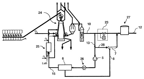
Figure 3 shows a representation of a blast furnace 24 for
producing pig iron with a pressure swing adsorption system 6.
The pig iron is produced in the blast furnace 24 with
CA 02752988 2011-08-18
54106-928
- 11 -
the addition of gas containing oxygen (preferably > 80% 02) and
with the charging of coke and ore. A partial amount of a waste
gas 10 of the blast furnace 24, known as top gas 13, is
branched off upstream of a pressure controller 23 and, after an
increase in the pressure by means of a compressor 5 and cooling
in a gas cooler 26, is fed to the pressure swing absorption
system 6 at a first pressure pi. A partial amount of the top
gas 13 is fed as propellant gas 28 to a jet pump 7 at a third
pressure p3, which generates the second pressure p2 or the
desorption pressure for the removal of 002 and/or H20 from an
adsorption separator of the pressure swing absorption system 6.
Here it is once again the case that p2<p1 and p2<p3. The
pressure swing adsorption system 6 separates CO2 and/or H20
from the waste gas, so that a cleaned waste gas 15 has a higher
reduction potential and a higher calorific value. After
optional pre-heating, this gas is fed to a reducing gas furnace
25 and the blast furnace 24, for example via the air-blast
tuyeres or oxygen nozzles, or .into the shaft of the blast
furnace above a cohesive zone. An export gas 12, consisting of
the propellant gas 28, the tail gas in the connecting line 8
and the remaining waste gas, is temporarily stored in a gas
accumulator 27, from where it is passed on for thermal use.
With respect to the details of the pressure swing adsorption
system 6, reference is made to Figure 2. Generating the
desorption pressure by the propellant gas 28 flowing through
the jet pump 7 once again has the following advantages: freedom
from maintenance of the jet pump, in particular no moving
parts, lower space requirement and lower procurement costs
compared with a compressor, and also no energy costs.
Figure 4 shows two schematic representations of jet pumps. The
representation on the left shows a jet pump 7 where the
propellant gas connection 21 and the pressure connection 19 lie
in one axis. The suction connection 20 is arranged at right
angles to the propellant gas connection/pressure connection
axis. In the case of the representation on the right, the
suction connection 20 and
CA 02752988 2011-08-18
54106-928
- 12 -
the pressure connection 19 lie in one axis; the propellant gas
connection 21 is arranged at right angles to this axis. It is
the case for both representations that the suction connection
20 is in connection with the region of narrowest flow cross
section of the jet pump and that a propellant gas is applied to
the propellant gas connection 21 at a pressure p3, thereby
establishing in the suction connection 20 a pressure p2 for
which P2 < p3.
Figure 5 shows a schematic representation of a series
arrangement of two jet pumps 7a and 7b. A connecting line 8 for
tail gas connects a suction connection 20 of the jet pump 7a to
a desorption connection 22 of an adsorption separator 16. The
pressure connection of the suction pump 7a is connected to the
suction connection of the suction pump 7b, whereby a
particularly low desorption pressure can be achieved. Both jet
pumps 7a and 7b are supplied with propellant gas by means of a
propellant gas connection 21.
In Figure 6, a schematic representation shows a parallel
arrangement of two jet pumps 7. Two connecting lines 8 for tail
gas respectively connect a suction connection 20 of the two jet
pumps 7 to a desorption connection 22 of an adsorption
separator 16. Both jet pumps 7 are supplied with propellant gas
by means of the propellant gas connections 21 thereof, whereby
the propellant gas 28 is distributed between two smaller
suction pumps. Moreover, simpler setting (open-loop or closed-
loop control) of the desorption pressure is possible by
changing an amount of propellant gas.
The method according to the invention and the use of the
apparatus according to the invention are not in any way
restricted to FINEXO installations (Figure 1) or blast furnaces
(Figure 3); rather, application in the case of natural-gas
direct reduction installations (for example of the HYLC, or
FINMETO type), COREXO installations or else combined direct
reduction installations is also advantageous.
CA 02752988 2011-08-18
54106-928
- 13 -
List of designations
1 Melter gasifier
2 Reduction reactor
3 Cascade of pre-reduction reactors
4 Gas scrubber
Compressor
6 Pressure swing adsorption system
7 Jet pump
8 Connecting line
9 Reducing gas
Offgas
11 Surplus gas
12 Export gas
13 Top gas
14 Waste gas
Cleaned waste gas
16 Adsorption separator
17 Valve
18 Cooling gas
19 Pressure connection
Suction connection
21 Propellant gas connection
22 Desorption connection
23 Pressure controller
24 Blast furnace
Reducing gas furnace
26 Gas cooler
27 Gas accumulator
28 Propellant gas