Note: Descriptions are shown in the official language in which they were submitted.
CA 02753142 2015-06-17
1
VIAL ADAPTER ASSEMBLY IN DRUG MIXING SYSTEM
FIELD OF THE INVENTION
The present invention relates to drug mixing systems generally, and
particularly to a
vial adapter assembly for use with a drug mixing system, which has a double
membrane that
allows free passage of air into the main body of the vial adapter, but
prevents passage
therethrough of liquid and air-borne particles, microorganisms and aerosol.
BACKGROUND OF THE INVENTION
Drug mixing systems are well known in the art. One particular drug mixing
system is
described in published PCT patent application WO 2005/041846, assigned to the
current
assignee of the present application. The drug system is commercially available
from Teva
Medical Ltd. and is sold under the brand name TevadaptorTm. It is a system for
safe
compounding and administration of hazardous intravenous drugs. TevadaptorTm
minimizes
the risk of exposure to hazardous drug substances, and eliminates the risk of
needle stick
injuries. The drug mixing system is intended for use with a luer fitted
hypodermic syringe,
and is particularly useful for handling toxic drugs such as antineoplastic
drugs.
The TevadaptorTm drug mixing system includes a receptacle port adapter that
can be
inserted into a port of a fluid receptacle, such as an IV bag. A vial adaptor
assembly is
provided for connection to a vial containing a drug. A syringe adapter element
may be
attached to a syringe and to the receptacle port adapter and/or the vial
adapter assembly. The
receptacle port adapter, syringe adapter element and/or the vial adapter
assembly may be
vented to the atmosphere in a manner that prevents release to the atmosphere
of possibly
harmful contents of the vial in a liquid, solid or gaseous form.
The syringe adapter element may have a needle that fluidly communicates with
the
contents of the syringe. The needle does not normally protrude outwards, but
rather is sealed
inside the syringe adapter element by a septum. The syringe adapter element
may be
assembled onto the luer tip of the syringe. The needle of the syringe adapter
element is now in
fluid communication with the contents of the vial but the contents do not flow
outwards
because the needle is sealed inside by the septum.
Similarly, the vial adapter assembly may have a needle that fluidly
communicates with
the contents of the vial, wherein the needle does not normally protrude
outwards, but rather is
sealed inside the vial adapter assembly by a septum. The vial may be pushed
onto the vial
adapter assembly, wherein the needle of the vial adapter assembly punctures
the septum of the
vial. The vial adapter assembly may then be pushed onto the syringe
CA 02753142 2011-08-19
WO 2010/099000
PCT/US2010/024246
2
adapter element, wherein the needle of the syringe adapter element punctures
the septa of
the syringe adapter element and the vial adapter assembly. This allows fluid
to flow from
the syringe through the needle of the syringe adapter element and through the
needle of
the vial adapter assembly to the vial.
After filling the vial with a desired amount of fluid, the vial adapter
assembly may
be separated from the syringe adapter element. Immediately upon separation,
the needle
of the syringe adapter element and the needle of the vial adapter assembly are
both sealed
by their respective septa. In this manner, no fluid drips outwards.
SUMMARY OF THE INVENTION
The present invention seeks to provide an improved vial adapter assembly for
the
Tevadaptor drug mixing system, particularly a vial adapter assembly that has a
double
membrane that allows free passage of air into the main body of the vial
adapter, but
prevents passage therethrough of liquid and air-borne particles,
microorganisms and
aerosol.
There is thus provided in accordance with an embodiment of the present
invention
apparatus for use in a drug mixing system including a vial adapter assembly
including a
main body element having a vial receiving portion and a needle puncturable
port, the
main body element including an axial hollow tubular portion which is in fluid
flow
engagement with a bore of a vial puncturing spike, the main body element
further
including a membrane support surface that supports a first membrane which is
in fluid
flow engagement with the vial puncturing spike via the bore and via a recess
formed in an
intermediate portion of the main body element, and a second membrane supported
by a
membrane support member and separated by a gap from the first membrane. The
first and
second membranes may be hydrophobic and generally parallel to one another.
In accordance with an embodiment of the present invention the membrane support
member is formed with vent holes. The membrane support member may include tabs
that
fit into grooves formed in the intermediate portion.
BRIEF DESCRIPTION OF THE DRAWINGS
The present invention will be understood and appreciated more fully from the
following detailed description, taken in conjunction with the drawings in
which:
Figs. 1A and 1B are respective exploded and sectional illustrations of a vial
adapter assembly of a drug mixing system of the prior art; and
Fig. 2 is a simplified partially sectional illustration of a vial adapter
assembly,
constructed and operative in accordance with an embodiment of the present
invention.
CA 02753142 2015-06-17
3
DETAILED DESCRIPTION OF EMBODIMENTS
Reference is now made to Figs. 1A and 1B, which illustrate a vial adapter
assembly 30
of a drug mixing system of the prior art, such as that described in published
PCT patent
application WO 2005/041846.
The vial adapter assembly 30 comprises a main body element 302 arranged
generally
about an axis 303. Main body element 302 may be integrally formed and
injection molded of
plastic.
Main body element 302 may include a rear portion 304, also referred to as a
vial
receiving portion, which is generally cylindrical and terminates in a forward
wall 306. Rear
portion 304 comprises a forward base section 308, rearward of which are
preferably formed
four tabs 310 each having a rectangular window 312.
Rearward of rectangular windows 312 and on an inner surface 314 of each of
tabs 310
there are preferably formed two radially extending inwardly facing protrusions
316 each
having an inclined surface. Protrusions 316 preferably terminate at a forward
end thereof in an
inwardly facing transversely extending protrusion 318. Rearward of protrusions
316, each of
tabs 310 preferably includes an outwardly tapered portion 320.
A hollow vial puncturing spike 322 extends rearwardly from a rearward surface
324 of
forward wall 306, and is surrounded by base section 308 and by tabs 310.
Rearward surface 324 additionally includes a circular cylindrical protrusion
325,
surrounding puncturing spike 322. Two radially extending bores 326 and 327
extend through
vial puncturing spike 322.
Forward of forward wall 306 of rear portion 304 there is formed an
intermediate
portion 328 which is generally rectangular, and includes axial hollow tubular
portion 330
which is in fluid flow engagement with bore 327 of vial puncturing spike 322.
At a top surface of intermediate portion 328 and slightly recessed with
respect thereto
there is formed a membrane support surface 332, having formed thereon a
plurality of
generally evenly distributed spherical protrusions 334, which are adapted to
support a first
membrane 336 (preferably hydrophobic) and prevent it from excessive inflation
and from
cracking. Membrane 336 is adapted to allow free passage of air into the main
body element
302, but to prevent passage therethrough of liquid and air-borne particles,
microorganisms
and aerosol. A preferred membrane 336 is Model VersaporTM 0.2 microns, which
is
commercially available from Pall Corporation of New York, U.S.A.
CA 02753142 2015-06-17
4
Membrane 336 is in fluid flow engagement with vial puncturing spike 322 via
bore
326 and via a recess 337 formed in intermediate portion 328.
A rim 338 surrounding support surface 332 is adapted to support an optional
carbon
cloth filter 340 and maintain it in a raised position above and spaced from
membrane 336.
Carbon cloth filter 340 is adapted to prevent toxic vapors from escaping from
main body
element 302, thus protecting users. A preferred carbon cloth filter 340 is
Model No. ZorflexTM
EMI, which is commercially available from Charcoal Cloth International Ltd. of
Houghton-le-
Spring, England.
Intermediate portion 328 tei minates at a forward end thereof in a generally
circular
wall 342. Forward of circular wall 342 there is formed a hollow neck portion
344, which is in
fluid flow engagement with hollow tubular portion 330 and with hollow vial
puncturing spike
322. Hollow neck portion 344 terminates at a forward end thereof in a
generally circular wall
surface 346.
Forward of neck portion 344 there is formed a forward facing portion 348, also
referred to as a needle puncturable port, which is adapted to sealingly
accommodate a
generally circular septum 350 on a seat 352 which is located at a forward end
of portion 348.
Forward facing portion 348 defines a central bore 354 which communicates
between tubular
portion 330 and septum 350.
Vial adaptor assembly 30 preferably additionally includes a covering element
360
which supports and covers membrane 336 and carbon filter 340. Covering element
360 is a
generally cylindrical, generally side-to-side symmetric, element and is
preferably formed with
a central opening 362 at a forward end thereof through which forward portion
348 extends.
Outer side surfaces 364 of covering element 360 are each formed with ribbed
grip
regions 366. An inner top surface 368 of covering element 360 is preferably
flat, and is
adapted to support the top surfaces of membrane 336 and carbon filter 340 and
to prevent
excessive inflation and cracking thereof.
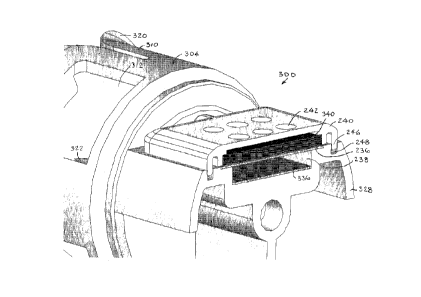
Reference is now made to Fig. 2, which illustrates a vial adapter assembly
300,
constructed and operative in accordance with an embodiment of the present
invention, with
like elements to vial adapter assembly 30 being designated by like numerals.
Vial adapter assembly 300 differs from vial adapter assembly 30 in that vial
adapter
assembly 300 includes a second membrane 236 supported by a membrane support
member
240. The second membrane 236 is separated by a gap 238 from first membrane
CA 02753142 2011-08-19
WO 2010/099000
PCT/US2010/024246
336. The first and second membranes 336 and 236 may be generally parallel to
one
another. Like the first membrane 336, the second membrane 236 may be
hydrophobic.
The membrane support member 240 may include tabs 246 that snugly fit into
grooves 248 formed in intermediate portion 328. Membrane support member 240
may be
formed with vent holes 242.
The pair of membranes 236 and 336 allow free passage of air into the main body
of the vial adapter, but prevent passage therethrough of liquid and air-borne
particles,
microorganisms and aerosol.
The carbon cloth filter 340 may be positioned above second membrane 236.
It is appreciated that various features of the invention which are, for
clarity,
described in the contexts of separate embodiments, may also be provided in
combination
in a single embodiment. Conversely, various features of the invention which
are, for
brevity, described in the context of a single embodiment, may also be provided
separately
or in any suitable subcombination.