Note: Descriptions are shown in the official language in which they were submitted.
CA 02753472 2011-08-23
WO 2010/103456
PCT/1B2010/050998
1
"Apparatus and method for manufacturing slabs with a veined effect"
*****
DESCRIPTION
The present invention relates to an apparatus and a method for manufacturing
conglomerate stone slabs which have veining similar to that present in natural
stone materials.
In particular, the invention relates to the manufacture of conglomerate stone
slabs
obtained from a mix of granulated stone and/or stone-like material and a
binder.
Hitherto various methods for manufacturing such a material are known,
including for
example the so-called Bretonstone technology used to manufacture slabs.
These slabs are manufactured using a special technology which involves the
preparation
of a starting mix comprising a stone and/or stone-like material and a binder,
together with
any additives.
Generally the binder may be of an inorganic nature, such as cement, or a
synthetic resin
which can be hardened by means of heat and/or a catalyst.
The starting mix is normally spread over a temporary support which may be a
conveyor
belt or a tray-like mould.
As is known, natural stone materials (such as marble and granite, to name the
most
common types) normally have irregular veining, mainly with a col our which
contrasts or in
any case is different from the basic colour of stone.
In the Bretonstone method hitherto a colouring substance is added after the
mix has
been deposited on the temporary support.
Said substance is distributed on the surface of the mix in an irregular
manner. Then the
mix is treated using a spiking apparatus so as to ensure that the colouring
agent penetrates
inside the mix.
This stage is preceded by a step involving vacuum vibrocompression of the mix.
During
this step the mix is subject for a given period of time and at a given vacuum
value to the
action of a press, while a vibratory movement at a predetermined frequency is
imparted to the
press ram.
The rough-formed slab thus obtained then undergoes a hardening step which
depends
on the type of binder used.
However, this method is unable to ensure veining throughout the thickness of
the slab
and is therefore suitable for applications where the edge (or thickness of the
article) is not
visible.
In fact the action of the spiking apparatus on the mix, following distribution
of the
colouring agent, is able to achieve the veining effect only over a depth of a
few millimetres
from the surface, equal to no more than half the thickness of the finished
slab.
Alternatively, it is possible to envisage the use of a weighing distributor of
the type
CA 02753472 2011-08-23
WO 2010/103456
PCT/1B2010/050998
2
described in the international patent application WO-A-2004/039547.
According to this production method the starting mix, before being loaded
inside a
metering device, is subject to the action of devices which apply liquid or
powder colouring
pigments onto its surface.
The mix comprising the colouring agent is conveyed to the distributor and
reaches it by
means of a free-falling action so that it undergoes further mixing which, on
the one hand,
ensures shortening of the veining and, on the other hand, diffusion of the
pigment within the
mass of the mix which is therefore at least partly coloured en masse.
Another type of technology which is known is Lapitech technology, a term which
is
understood as referring in general to the technology, the associated method
and the resultant
slabs. Lapitech technology is used for the manufacture of slabs similar to
ceramic articles
intended for the internal and external cladding of buildings.
In this case also a starting mix is prepared using a granulated stone, stone-
like or ceramic
material, preferably in the form of sand of suitable dimensions. The
granulated product is
mixed with the components which are normally used for the manufacture of
ceramic
materials, usually in powdery form and consisting mainly of kaolin or clay. A
binder, for
example sodium silicate in aqueous form or silicasol is then added to the
mixture so as to
make the mixture moist.
The mix is then extended over a temporary support with a given thickness and
then
undergoes a vibrocompression step, resulting in a rough-formed slab.
Subsequently the
rough-formed slab thus obtained undergoes drying in order to remove the water
and then
firing in an oven at a temperature of about 1200 C.
This technology, as regards the veining effect obtained, is also subject to
limitations and
drawbacks similar to those mentioned in connection with Bretonstone
technology.
The industrial patent application WO-A-2009/010406 describes a method and
apparatus
for manufacturing slabs with a veined effect.
The procedure and method described are applicable both to Bretonstone
technology
and to Lapitech technology and the apparatus used is substantially that
described in the
international patent application No. WO-A-2006/045728.
Tti the application WO-A-2009/010406 the method is substantially the same as
that
described above except for a step involving the non-uniform distribution of
the colouring
agent on the surface of the mix. The distribution of the colouring agent is
performed by
means of at least one dispensing device which is positioned at the downstream
end of an
extractor belt which forms the bottom of the apparatus, so as to dispense the
colouring agent
onto the surface of the layer of mix conveyed by said extractor belt towards
the position
where it falls freely onto said temporary moulding support.
The colouring or pigmenting agent used may be in solid form (dry powder) or
liquid
3
form and may be supplemented or replaced with coloured or reflective granules.
By means of this method it is possible to obtain slabs and articles which have
a veined
effect throughout their thickness.
However this method is also not without drawbacks.
Firstly, performing addition of the colouring agents before the
vibrocompression step
has the effect that the liquid colouring agent is diffused lightly within the
mass of the mix.
This diffusion results in blurred veining which is not clear and well-defined
like the
veining present in natural stone.
Moreover, still with reference to the liquid colouring agent, cleaning of the
plant is
particularly complex since each nozzle must be disassembled and cleaned and
each individual
pipe supplying the colouring liquid to the nozzles must be cleaned.
The same procedure must also be performed in the case where it is required to
change
the veining effect to be performed on the slab, both in terms of different
colouring and in terms
of a different effect associated with the arrangement of the veining.
The use of the powdery colouring agent would result in a more pronounced
veining,
similar to that of natural stone, but considerable difficulties exist with
regard to distribution of
the powdery colouring agent, both in terms of the random nature of the
distribution and in
terms of suitable distribution of the colouring agent.
The object of the present invention is therefore to overcome the drawbacks of
the prior
art.
A first object of the present invention is to obtain a slab or article which
has a
pronounced and random veined effect similar to that present in natural stone.
A second object of the present invention is to obtain a veined effect
throughout the
thickness of the slab or the article.
A third object of the present invention is to provide an apparatus which is
able to obtain
a pronounced and random veined effect throughout the thickness of the slab or
the article.
A further object of the present invention is to provide an apparatus in which
changing
of the colouring agent is facilitated so as to obtain effects of a different
type on the slabs or
the articles.
According to one aspect of the invention there is provided a
dispensing/spreading
means for dispensing a powdery colouring substance onto the surface of a mix
comprising
stone, stone-like, glass or ceramic material, said means comprising at least
one dispensing
device designed to contain and dispense a powdery colouring substance;
said dispensing device comprising:
CA 2753472 2017-12-20
3a
two inclined walls which converge downwards so as to form a prism shaped
funnel;
flexible metal strips fixed to the inclined walls; and
a metering cylinder which:
forms a bottom of the prism-shaped funnel;
is kept in contact with the metal strips;
is rotated about an axis of the metering cylinder by a motor; and
has on a surface of the metering cylinder a plurality of recesses;
said dispensing/spreading means comprising:
at least one spreading device comprising at least one rotating perforated
plate
positioned underneath said dispensing device from which the at least one
spreading device
receives a metered quantity of said colouring substance from said dispensing
device and
distributes the colouring substance over the surface of the mix.
According to another aspect of the invention there is provided a
dispensing/spreading
means for dispensing a powdery colouring substance onto the surface of a mix
comprising
stone, stone-like, glass or ceramic material, said means comprising at least
one dispensing
device designed to contain and dispense a powdery colouring substance, wherein
the
dispensing/spreading means comprises:
at least one spreading device comprising at least one rotating perforated
plate
positioned underneath said dispensing device from which the at least one
spreading device
receives a metered quantity of said colouring substance and distributes the
colouring substance
over the surface of the mix; and
said at least one dispensing device comprises two inclined walls which
converge
downwards so as to form a prism-shaped funnel, a bottom wall which closes said
funnel and
has a plurality of holes arranged in a random manner for allowing the powdery
colouring
substance to pass through, and an opening/closing device associated with said
holes.
According to yet another aspect of the invention there is provided an
apparatus for
distributing in a thin layer a mix comprising stone or ceramic material on an
underlying
support, comprising:
a mix distributor in the form of a hopper having:
a top opening for loading the mix bounded by side walls, one of these walls
being shaped with a profile which is convex towards the inside of the hopper;
and an opening for discharging the mix, defined by a bottom end of said shaped
wall and by an extractor belt positioned below said hopper, said belt forming
with an
CA 2753472 2017-12-20
3b
upper side the bottom of the hopper itself and being operated so as to deposit
a uniform
layer of said mix, after the mix has flowed inside the hopper and has passed
out through
said discharge opening, onto said support positioned at a lower level than
said extractor
belt, while a relative movement of said hopper and said support is maintained
so as to
obtain a uniform layer of mix on said support; and
a dispensing/spreading means for distributing a powdery colouring substance
over the
surface of the mix, said means being designed to sprinkle the powdery
colouring substance
onto the mix in a position situated between the discharge opening of the
hopper and the end
of the extractor belt where discharging of the mix onto the support occurs;
wherein the
dispensing/spreading means comprises a dispensing/spreading means as described
herein.
According to still another aspect of the invention there is provided a method
for
distributing in a thin layer a mix based on stone or ceramic material and/or a
binder on a
support, comprising the steps of:
distributing a mix on an extractor belt, said mix being contained in a mix
distributor;
distributing a powdery colouring substance between a discharge opening of a
hopper
and one end of the extractor belt, using dispensing/spreading means; and
depositing the mix by means of falling thereof from the end of the extractor
belt onto
the support; wherein said dispensing/spreading means is as described herein.
The further advantages and characteristic features of the present invention
will become
clear from the detailed description which follows of a number of examples of
embodiment,
provided by way of a non-limiting example, with reference to the accompanying
drawings in
which:
Fig. 1 shows a laterally sectioned view of a first embodiment of an apparatus
for
distributing the colouring agent in a plant for manufacturing conglomerate
slabs according to
CA 2753472 2017-12-20
CA 02753472 2011-08-23
WO 2010/103456
PCT/1B2010/050998
4
the invention;
Fig. 2 shows a laterally sectioned view of a second embodiment of the
apparatus for
distributing the colouring agent according to the invention;
Fig. 3 shows a laterally sectioned view, on a larger scale, of means
for
dispensing/spreading the powdery colouring substance according to a first
embodiment of
the invention;
Fig. 4 shows a laterally sectioned view of a device for dispensing
powdery colouring
substance according to a possible embodiment of the invention;
Fig. 5 shows a laterally sectioned view of the dispensing/spreading
means for
distributing the powdery colouring substance according to an embodiment of the
invention;
Fig. 6 shows a laterally sectioned view of a second embodiment of the
dispensing
device according to the invention;
Fig. 7 shows a view from one end of the fixing device associated with
the device for
spreading the powdery colouring substance according to Fig. 1;
Fig. 8 shows a perspective view of the spreading device according to Fig.
1;
Fig. 9 shows a perspective view of a detail of the spreading device
according to Fig.
8;
Fig.10 shows a front view of the apparatus according to invention; and
Fig. 11, Fig. 12, Fig. 13, Fig. 14, Fig. 15, Fig. 16 show a possible sequence
of the stages
for construction of the device for spreading colouring substance according to
the invention.
Figures 1 and 2 shows an apparatus, denoted overall by the reference number
12, for
distributing a mix 14 in a thin layer on a support 16 formed by a tray-like
mould. Said mix 14
comprises a granulated stone, stone-like or ceramic material and/or an organic
or inorganic
binder.
Still with reference to Figure 1 the following are defined:
- a longitudinal direction parallel to the direction of relative movement
of the apparatus
12 with respect to the support 16, denoted by the double arrow FL;
- a transverse direction perpendicular to the direction of relative movement
of the
apparatus 12 with respect to the support 16 and perpendicular to the cross-
sectional plane
shown in Figure 1; and
- a transverse plane containing the transverse direction and perpendicular
to the
longitudinal direction.
The apparatus 12 according to the invention comprises a mix distributor 18
which is
substantially the same as that described in the patent application WO
2006/045728.
It comprises a hopper 20 with a top loading opening 22 suitable for loading
the mix 14
and with a shaped wall 21 having in particular a convexity directed inwards.
The hopper 20 has a discharge opening 24 on the bottom, extending in a
transverse
CA 02753472 2011-08-23
WO 2010/103456
PCT/1B2010/050998
plane perpendicular to the direction of relative movement FL.
The discharge opening 24 is provided with a gate 27 for controlling the
throughput of
the mix 14 passing out through the discharge opening 24.
The apparatus 12 according to the invention also comprises an extractor belt
19 which is
5 positioned
underneath the hopper 20 and which in particular forms the bottom thereof. The
extractor belt 19 allows the mix 14 to be transferred, from the hopper 20 to
the support 16
which is positioned below the extractor belt 19, by means of a free-falling
action from the
downstream end of the extractor belt 19.
As mentioned above, the mix distributor 18 is movable in both directions
relative to the
support 16 in the direction indicated by the arrow FL at a constant speed so
that material is
deposited on the support with the desired constant thickness.
The relative movement of the distributor 18 and the support 16 is made
possible by
means of motor-driven carriage structure which is shown in simplified form and
indicated
overall by the reference number 50.
The carriage structure 50 comprises a frame 52 to which the distributor 18 is
rigidly
fixed.
Said frame 52 is mounted on wheels 54, 56 which engage with coplanar rails 59
situated
along the two sides of the support 16 and allow the movement of the
distributor in the
direction indicated by the double arrow FL.
The movement of the distributor is produced in a known manner by motor means
(not
shown).
Tti one possible embodiment it is possible to envisage the arrangement of a
protective
film 32 between the mix 14 and the shaped wall 21 of the hopper 20, as shown
in WO-A-
2006/45728.
Said film 32 made of non-adhesive material has the purpose of protecting the
shaped
wall 21 from any depositions formed by residual amounts of the mix 14.
A film feeding system, denoted overall by the reference number 34, is provided
for
allowing the continuous renewal of said film and comprises a feed roller 36
around which the
protective film 32 is wound.
A second reel 38, operated by an electric motor (not shown), is positioned on
the
outside of the hopper 20, in a position raised with respect to the bottom
thereof and
therefore with respect to the extractor belt 19, this reel allowing unwinding
of the film 32
from the roller 36 and movement thereof in the direction from the upper
opening 22 towards
the discharge opening 24.
The extractor belt 19 is mounted endlessly wound around two rollers 40, 42,
the roller
being operated by a motor 41 and the driven roller 42 performing the usual
transmission
function.
CA 02753472 2011-08-23
WO 2010/103456
PCT/1B2010/050998
6
The direction of rotation of the rollers 40, 42 is such that the extractor
belt 19 conveys
the bottom layer of the mix 14 (with which it makes contact) towards the
discharge opening
24 of the hopper 20, i.e. towards the downstream end 25 of the belt 19.
In one possible embodiment of the invention the upper surface of the belt 19,
i.e. the
surface of the belt 19 which transfers said bottom layer of the mix, is
protected with a film of
plastic material 44, for example consisting of polyethylene, which is unwound
from a roller 46
and reaches a motor-driven receiving roller 48. In order to prevent the film
44 from being
displaced off-centre with respect to the upper surface of the belt 19, the
latter has a certain
degree of roughness.
The upper section of the belt 19 which conveys the mix 14 has an inclination
of between
10 and 20 and preferably equal to about 15 in the direction of feeding of
the mix 14.
The apparatus 12 comprises dispensing/spreading means for distributing a
powdery
colouring substance 11 having a particle size generally less than 0.5 mm on
the surface of the
mix, said means being denoted overall by the reference number 26.
Said means 26 comprise at least one dispensing device 28 for the powdery
colouring
substance 11 and also comprise at least one spreading device 30 suitable for
receiving the
powdery colouring substance 11 from said dispensing device 28 and for
sprinkling it over the
upper surface of the mix 14. Tti particular the colouring substance 11 may be
sprinkled in a
position situated between the discharge opening 24 of the hopper 18 and the
downstream
end of the extractor belt 19 where the mix 14 is discharged by falling onto
the support 16.
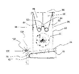
With reference now also to Figure 4, the dispensing device 28 comprises a
support
structure 60 which is rigidly fixed to the structure of the distributor 18 and
supports two
inclined walls 62, 64 which converge downwards, forming a prism-shaped funnel
68 with an
opening 66.
The prism-shaped funnel 68 acts a storage vessel for the powdery colouring
substance
11.
According to a first embodiment, flexible metal strips 70, 72 are fixed to the
bottom of
the inclined walls 62, 64. Said flexible strips 70, 72 may be fixed to the
inclined walls 62, 64 in
a rigid or removable manner.
The strips 70, 72 are kept in contact via a light pressure (for example making
use of their
resilient nature) with a metering cylinder 74 which forms the bottom of the
prism-shaped
funnel 68 and is operated by a motor 35 (shown in Fig. 10) in the direction of
the arrow F.
The metering cylinder 74 has its axis of rotation perpendicular to the
direction F, of
displacement of the distributor 18.
The surface of the cylinder 74 has, formed therein, recesses 76, 78 which are
situated in
non-symmetrical positions with respect to the axis of symmetry of the cylinder
and in
positions distributed in a non-ordered manner along the said axis.
CA 02753472 2011-08-23
WO 2010/103456
PCT/1B2010/050998
7
The cylinder 74 has thc form of the recesses 76, 78 which is variable in a non-
ordered
manner.
In particular the circumferential and longitudinal extension and the depth of
the recesses
76,78 may vary.
In other words each recess has a circumferential and longitudinal extension as
well as a
depth which is different and in no way related to that of the adjacent
recesses on the surface
of the cylinder, such that it may be described as being a random distribution.
When said recesses 76, 78 are situated in a position facing the inside of the
funnel 68
they are filled and, by means of rotation of the metering cylinder 74, since
they start to face
downwards, they discharge their contents onto the underlying spreading device
30.
In this way the at least one dispensing device 28 distributes in a random
manner the
colouring substance 11 onto at least one spreading device 30.
In one possible embodiment said dispensing device 28 may envisage the use of
two or
more prism-shaped funnels 68, each associated with a respective metering
cylinder 74.
In this way, not only is it possible to obtain a distribution of the colouring
substance 11
which is even more random, but it is also possible to use several colouring
substances of a
different type and different colour.
Each metering cylinder 74 may be provided underneath with one or more vertical
cleaning blades (not shown), made of spring steel, these being able to be
inserted inside each
recess 76, 78 so as to scrape off any pigment which may remain attached to the
cavities.
With reference now to Figure 6, an alternative embodiment of the dispensing
device 28
according to the invention is now described.
In this case it is envisaged using the abovementioned prism-shaped funnel 68
comprising a bottom wall 67.
The bottom wall 67 is provided with a plurality of holes 69 for allowing the
powdery
colouring substance to pass through from the funnel 68 to the spreading device
30 situated
underneath.
Said holes 69 are present over the whole transverse extension of the apparatus
in
random positions so as to increase the random nature of metering of the
colouring substance.
A bush 73 is inserted inside each hole 69 and acts as a through-fall orifice
for the
powdery colouring substance, the internal diameter of which may assume
different values
depending on the type and quantity of colouring substance to be dispensed.
Said bushes 73 have an external diameter which is the same as the internal
diameter of
the holes 69.
A device 65 for opening/closing the holes is associated with the bottom wall
67 and
comprises at least one hinged opening/closing mechanism 178 associated with
each hole 69
in the bottom wall 67.
CA 02753472 2011-08-23
WO 2010/103456
PCT/1B2010/050998
8
The hinged opening/closing mechanism 178 comprises:
- a lever 180 hinged at a middle point between the ends 184, 185;
- a closing member 186 associated with the bush 73 for closing the hole 69
and
connected to a first end 184 of the lever 180;
- an actuator 188 for actuating the hinged mechanism 178, connected to a
second end
185 of the lever 180.
The actuator 188 comprises in turn a linear electromagnet or an
electromechanical
device provided with a movable stem 190 hinged to the second end 185 of the
lever 180.
In the rest position the stem 190 protrudes externally and is kept in this
position owing
to the resilient action exerted by a compressed spring (not shown) which
pushes the stem
towards the outermost position.
When the electromagnet is actuated, the stem 190 is retracted, compressing
further the
spring so that, as soon as the power supply is interrupted, the stem moves out
again.
As shown in Figure 6, in the rest position the actuator 188 closes off the
hole 69 by
means of the closing member 186.
When the electromagnet 186 is energized, the closing member 186 moves from the
closed position.
Filergization of the electromagnet is managed by a programmable control unit
(not
shown) so as to cause opening and closing of each hole 69 in a random and
programmed
manner as defined above.
In both embodiments described vibration-generating means 93 may be associated
with
the bottom or the inclined walls 64, 62 of each funnel 68, with the aim of
assisting the flow of
powdery colouring substance through the bushes 73.
With reference now also to Figures 5, 7 and 8, the spreading device 30 is
described in
detail.
The spreading device 30 allows distribution and spreading, over the surface of
the mix
14, of the powdery colouring substance 11 dispensed by the dispensing device
28, preferably
in a position situated between the discharge opening 24 of the hopper 20 and
the end 25 of
the extractor belt 19.
According to a first embodiment the spreading device 30 comprises at least one
moving
perforated plate 100 positioned underneath the dispensing device 28 from which
it receives a
metered quantity of said colouring substance 11.
In particular the at least one plate 100 is able to move in a longitudinal
transverse
direction, vibrate or rotate about a transverse axis.
In a second embodiment the spreading device 30 is a rotating structure
comprising a
series of differently inclined perforated plates in an interlocking
arrangement. In one
particular constructional form the device 30 comprises two end flanges 80, 82
facing each
CA 02753472 2011-08-23
WO 2010/103456 PCT/1B2010/050998
9
othcr at a distance substantially equal to thc width of the underlying layer
of mix 14 conveyed
by the extractor belt 19, i.e. in a direction perpendicular to the arrow FL.
A plurality of preferably metallic rods 84 connect the flanges 80, 82
together. The rods
may be connected to the flanges 80, 82 in a non-permanent manner, for example
by means a
screw and nut system. In this ease the end of the rod is provided with an
external thread, and
the flange 80 or 82 is provided with a through-hole from which the end of the
rod projects
and is engaged and locked with a nut 90.
In an alternative embodiment, the connection may be permanent in nature, for
example
by means of butt-welding of the ends of the rod 84 and flange 80 or 82.
The rods 84 are preferably positioned at the periphery of the flanges 80 or
82, in the
vicinity of the peripheral edge 92 of the flange itself (see Fig. 7).
The cage-like structure thus formed occupies a substantially cylindrical
volume and
supporting and connection means in the form of cylindrical pins 98, 99
projecting towards
the outside of said flanges 80, 82 are rigidly fixed to the outer sides of
said flanges 80, 82. The
pins 98, 99 are used for supporting the cage and for connection to motor means
95, shown in
Fig. 10, able to cause rotation of the cage structure about its longitudinal
axis. A plurality of
plates, indicated by the overall reference number 100 in Figure 8, are rigidly
fixed onto the
said cage structure. Said plates 100 are provided with holes 104 over the
whole of their
surface; for greater simplicity and clarity, the holes have not been shown in
the accompanying
figures, except in the case of Figure 7, said holes 104 allowing the plates
100 to act as a
"sieve" for the colouring powder 11 supplied by the dispensing means 28. The
holes 104 have
a diameter of about 2-5 mm.
Moreover, as can be understood in particular from Figure 8, the arrangement of
the
plates 100 may be random and the plates 100 are inclined with respect to the
main axis of the
cage structure.
In particular, the plates 100 are connected to the cage structure by means of
a weld
performed on two rods 84 which are not consecutive and in a substantially
diametral position.
Said plates 100 may be welded to the rods 84 both by means of a weld on their
flat
surface or by means of a weld along their thickness.
Ttl an alternative embodiment it is envisaged using a single rod 84 arranged
centrally on
the cage structure and essentially connecting together the centres of the
flanges 80, 82. The
plates 100 are welded to this single rod 84 in the same manner as described
above.
Figures 11 to 16 shows a possible sequence for assembly of the plates
according to a
possible enibodiment.
According to this embodiment it is envisaged using three types of rectangular
plate 140,
141, 142 and three types of triangular plate 143, 144, 145. "Types of plate"
is understood as
referring to plates with a different size, form and spatial orientation.
CA 02753472 2011-08-23
WO 2010/103456
PCT/1B2010/050998
Figure 11 shows the cage structure with a first rectangular plate 140 which is
welded to
the rods 84 along its thickness. The first rectangular plate 140 is positioned
in a direction
substantially transverse, but inclined with respect to the main axis of the
spreading device
(30).
5 With reference
now to Figure 12, this also shows a second plate 141 which is also
rectangular and welded to the rods 84 along its thickness. This second
rectangular plate 141 is
also positioned in a direction substantially transverse, but inclined in the
opposite direction to
the first rectangular plate 141 so that the first and second rectangular
plates 140, 141 converge
towards each other and towards the inside of the spreading device 30.
10 Fig. 13 shows
the incorporation of a third rectangular plate 142 lying in a plane
substantially transverse to said axis of said spreading device 30, but
inclined with respect to
the plane in which said first and second rectangular plates 140, 141
respectively lie. The plate
142 is also welded to the rods 84 by means of welds provided along their
thickness.
With reference to Fig. 14, this shows the incorporation of a first triangular
plate 143 in a
position situated between the two plates 141 and 142, being in a position
substantially parallel
to the main axis of the cage structure. The plate 143 has its edges welded to
the plates 141
and 142 and its base directed towards the outside of the cage structure and
the opposite
vertex directed towards the centre thereof.
Fig. 15 shows the structure according to Fig. 14 with a second triangular
plate 144
welded parallel to the main direction of the cage structure. Like the plate
143 it is welded to
the plates 141 and 142 parallel to the main direction of the cage structure,
but in a plane
different from that of the plate 143.
Figure 16 shows the complete structure of the spreading device 30 with also
the third
triangular plate 145. The plate 145 is welded in a manner similar to that of
the previous
triangular plates in particular between the rectangular plates 140 and 141.
Figure 7 shows a system for supporting and locking the spreading devices 30 to
the
structure of the apparatus 12, denoted overall by the reference number 94.
The support and locking system 94 extends substantially in the transverse
plane defined
above. In particular, the locking system 94 comprises:
- a fixed bracket 108 rigidly fixed to the structure of the apparatus 12 on
which
two idle support wheels 110, 112 for rotatably supporting the pin 98 are
mounted;
- a lever 116 with a first end 117 having a hinge 118 at one end of the
fixed
bracket 108; an idle locking wheel 120 in contact with the pin 98 is mounted
on said
elbow lever 116; in particular, in the operating or closing position, said
wheels 110,
112 and 120 are located at the vertices of a triangle; and
- a second end 119 of the elbow lever 116 can be fixed to the bracket 108
by
means of threaded pin 122 rotatable by means of a knob 124.
CA 02753472 2011-08-23
WO 2010/103456
PCT/1B2010/050998
11
As shown in Figure 7, said wheels 110, 112 and said wheel 120 engage with a
circumferential groov e 126 (see Figure 9) formed on the pin 98 for supporting
and axially
locking the cylindrical cage 30, preventing displacements in the axial
direction.
Preferably, the apparatus 12 according to the invention at the end 25 of the
extractor
belt 19 comprises a fragmenting device or roller denoted overall by the
reference number 130.
With reference to Figure 5, said fragmenting roller comprises a support shaft
132 having
its ends fixed to the structure of the apparatus 12 so as to allow rotation
about the axis of the
shaft 132.
A plurality of pins 134 which may also be of varying length project radially
from the
shaft 132.
The shaft 132 is rotated by a motor 133 (shown in Figure 10) so that the pins
134
penetrate into the mix 14, helping the previously distributed powdery
colouring substance 11
penetrate into the mix 14, and breaking up the mix into lumps with a size
depending on the
length of the pins 134.
According to a possible embodiment of the present invention, in order to
increase the
random nature of the veining and therefore produce a finished product which is
as similar as
possible to natural stone, several dispensing devices 28 and several spreading
devices 30 may
be provided, as shown in Figures 1, 2,3 arid 5.
Solutions are therefore envisaged where the dispensing devices 28 and
spreading devices
30 are several in number and in particular without there being necessarily a
direct relation
between their number.
Moreover said devices 28, 30 may also be installed with their longitudinal
axis riot
parallel to the transverse axis of the apparatus.
The operating principle of the apparatus 12 according to the invention is now
described
in detail.
The initial configuration of the apparatus 12 is that where the mix
distributor 18 is
empty, i.e. does not contain any mix 14.
The hopper 20 is then filled via the opening 22, while the gate 27 is closed
so as to
prevent the hopper 20 from emptying.
When the hopper 20 contains a suitable amount of mix, the gate 27 is opened
and at the
same time the motor-driven carriage structure 50 is operated. The relative
speed of the tray 16
and the distributor 18 varies depending on the density of the mix distributed
on the extractor
belt.
The extractor belt 19 operated by the motor 41, forming the bottom of the
hopper 20,
causes feeding of the mix 14 in the direction of the discharge opening 24 and
then the end 25
of the extractor belt 19. In view of the raised position of the extractor belt
19 situated above
the tray 16, the mix falls into the tray 16 when it reaches the end 25 of the
extractor belt 19.
CA 02753472 2011-08-23
WO 2010/103456
PCT/1B2010/050998
12
The controlled speed of displacement of the distributer 18 with respect to the
tray 16 allows
deposition of a layer with a constant mass.
In the method according to the invention a powdery colouring substance with a
particle
size normally less than 0.5 mm is added, using the dispensing/spreading means
26 for
distributing the powdery colouring agent 11 preferably between the discharge
opening 24 of
the hopper 20 and the end 25 of the extractor belt 19.
As already described, in a first embodiment, the colouring substance 11 is
loaded into
the at least one prism-shaped funnel 68 and accumulates above the dispensing
cylinder 74.
The bottom part of the prism-shaped funnel is formed by flexible strips 70, 72
in
contact with the dispensing cylinder 74.
The recesses 76, 78 provided on the cylinder 74 are filled with colouring
substance 11
when they face the inside of the funnel 68.
Dispensing of the powdery colouring substance is performed by means of
rotation,
about its axis, of the dispensing cylinder 74 so that the recesses 76, 78,
moving until they
communicate at least partially with the part of the means 30 situated
underneath the cylinder
74, allow their contents to fall out.
The flexible strips 70, 72 control and favour discharging of the colouring
agent onto the
successive spreading devices 30, distributing the colouring substance in a
random manner.
In this way the dispensing device 28 distributes in a random manner the
colouring
substance 11 above the spreading device 30.
Moreover, in accordance with the second embodiment of the dispensing device 28
shown in Fig. 6, the control unit (not shown) manages the actuators 187 and
188 so that the
powdery colouring substance covers in a random and programmable manner the
surface of
the spreading device 30.
The control unit also manages the duration of opening and/or closing of the
holes 69,
71 by the closing members 196, 186 and the rotation of the spreading devices
30, adjusting
their speed.
According to a further embodiment, the control unit (not shown) may manage
rotation
of the dispensers 28 and rotation of the spreaders 30, adjusting their speed.
The spreading devices 30, described previously, in view of their
configuration, allow the
powdery colouring substance to pass through the holes 104.
In particular they are imparted a movement and are positioned underneath the
dispensing device 28 from which they receive a metered quantity of said
colouring substance
11.
In an alternative embodiment the spreading device 30 is imparted a continuous
or
discontinuous alternating movement.
In this way it is therefore possible to distribute the powdery substance 11
randomly over
CA 02753472 2011-08-23
WO 2010/103456
PCT/1B2010/050998
13
the whole of the mix 14 passing beneath the spreading device.
It is understood that the present invention is applicable to the structures of
known
machines and in particular it is understood that the present apparatus and the
present method
are applicable both to Bretonstone technology and to Lapitech technology.
With regard to the embodiments described above, the person skilled in the art
may, in
order to satisfy specific requirements, make modifications to and/or replace
elements
described with equivalent elements, without thereby departing from the scope
of the
accompanying claims.