Note: Descriptions are shown in the official language in which they were submitted.
CA 02753530 2011-08-24
WO 2010/098833
PCT/US2010/000520
IMPROVED END CONNECTOR FOR HIGH PRESSURE REINFORCED RUBBER HOSE
Technical Field of the Invention
[001] The present invention relates generally to the reinforced rubber hose
industry and in
particular to swaged hose couplings used to terminate large diameter high
pressure flexible
reinforced rubber hose used in the energy, marine, petrochemical and like
industries which
can meet the newer API standards.
Background of the Invention
[002] High-pressure rubber hose is used in many instances in industry but
particularly in the
mining, construction, energy, marine and petrochemical industries. Flexible
rubber hose is
used to transfer fluids under various pressures and temperature between two
points, one or
both of which, may move relative to each other or to another fixed point in
space. Piping at
the two points is generally metal (or some other form of fixed conduit) and
the flexible hose
Must attach to the piping at both ends. This requires a coupling on each end
of the hose.
[003] In the drilling industry, a flexible rubber hose runs between the
pump piping system
on the rig and the kelly that is coupled to the rotating drill string. The
pump system forces
drilling fluid down the center of the drill pipe, and back through the
wellbore, in order to
flush cuttings from the wellbore (plus providing wellbore stability, etc.). In
this instance, the
flexible hose is subjected to high pressures. The high pressure is required to
both transfer
drilling fluid into the wellbore and overcome static return head pressures ¨
the deeper the
wellbore, the higher the pressure.
[004] The rotary drilling hose is subject to further stress in that it
hangs down within the
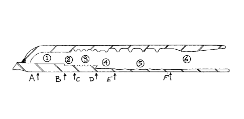
derrick supported at either end by the metal coupling on the hose and the fact
that the kelly is
moved up and down literally thousands of times during the drilling operation.
This means
that the hose is subject to stress at the metal coupling (in addition to being
subject to stress
throughout its length). Thus, a highly reliable bond between the hose and the
coupling is
required for protection of personnel and equipment. If the hose breaks loose
from the
coupling, it could easily fall and cause severe damage on the drill floor of
the rig. In a similar
manner, if the hose breaks, circulation may be lost resulting in a well
blowout situation.
[005] In order to obtain a high-pressure flexible rubber hose (the term
rubber is used
generally and does not specifically mean natural occurring rubber gum), a hose
manufacturer
incorporates a reinforcing material. Thus, the hose will consist of an inside
sealing
CA 02753530 2011-08-24
WO 2010/098833
PCT/US2010/000520
- 2 -
membrane ¨ the fluid tight element, an inner rubber element, a reinforcing
element, an outer
rubber element, and finally some sort of abrasive resistant covering. The
reinforcing element
can be polyester or similar organic material, carbon fiber or similar high
technology material
or metal (steel) generally in the form of wire or cable. The reinforcement
generally is used in
multiple layers called "plys" And usually made of steel.
[006] There are four types of reinforcing employed by the hose manufacturer
that is set
down in even layers ¨ i.e., 2 layers, 4 layers, 6 layers, etc., and grading
systems are used to
specify burst pressures for hose. For example, in the rotary drilling
industry, grade C hose
has a minimum burst pressure of 10,000 psi, grade D hose has a minimum burst
pressure of
12,500 psi and grade E hose has a minimum (guaranteed) burst pressure of
18,750 psi. Grade
C and D hose are 2 ply hose, although there is some 4 ply D hose. Most grade E
hose is 4
ply. Swage end connectors are currently available for two ply hose and
therefore the burst
pressure range for C and D hoses is covered by the current art.
[007] Generally a hose manufacturer manufactures flexible hoses to specific
order by the
purchaser who specifies length, diameter, pressure, service ratings and
required end
connections. These flexible hoses are generally referred to as a "hose
assembly with end
connectors" or "a built-up hose assembly." This term is used throughout the
industry.
[008] In a built up hose assembly with end connections, the manufacturer,
during the course
of manufacturing terminates the rubber hose into a metal fitting (the end
connector) as
specified by the purchaser. Thus, the manufacturer would make the inner rubber
membrane
(1st Carcass) and its associated inner seal layer (tube or inner tube) and
terminate this
assembly in the end connector. The manufacturer would then add the wire
reinforcement, as
needed, terminating each reinforcing wire (or cable) in the end connector. Two
techniques
are typically employed by hose manufacturers for terminating the wire
reinforcing in or on
the end connector itself but are beyond the scope of this discussion. Finally
the outer rubber
layer (2nd Carcass) and outer cover (cover) would be formed about the
reinforcing wire or
cable and the overall product vulcanized to achieve a cohesive product.
[009] It takes time to manufacture a hose assembly with end connections by
this method and
often such a hose is needed almost immediately by industry. In order to
service this demand
a separate industry termed the local market distributor has evolved. The local
market
distributor keeps bulk reinforced hose ¨ hose without connectors ¨ in
inventory. The
purchaser would specify the hose requirements ¨ diameter, length, pressure
rating and end
CA 02753530 2011-08-24
WO 2010/098833
PCT/US2010/000520
- 3 -
connectors ¨ to the local market distributor. The local market distributor
then takes bulk
reinforced rubber hose from inventory, cuts the hose to required length, and
places a coupling
on each end of the hose. Bulk hose is available in varying lengths from a hose
manufacturer,
and the actual bulk length (between 90 and 110 feet) will depend on the
mandrel used by the
manufacturer.
[010] The resulting hose is called a SWAGED or CRIMPED HOSE, depending on
the
method used to "place" the end connector onto the hose, where the term "place"
is being used
to include both swaging and/or crimping operations. It should be noted that
swaging and
crimping accomplish similar end results.
[011] The current state of the art in swaged (or crimped) connectors has
evolved to using an
outer ferrule with lands (internal ridges) that are compressed around the end
of a reinforced
hose about a stem that is inserted into the end of the hose. The stem may or
may not have
barbs that are meant to improve the "grip" between the hose and the end
connector. Often,
the outer layer of the reinforced hose is "skived" which means that the outer
carcass (the
outer layer of rubber and abrasive resistant covering) is removed thereby
exposing the
reinforcement (although some local distributors do not skive).
[012] The reinforced hose is actually held in the end connector by the
ridges of the ferrule
gripping the reinforcement via compression of the hose against the stem. The
compression
operation (swaging or crimping) of the ferrule against the reinforcement and
against the inner
stem creates severe stress and strain within the rubber of the hose and in
particular the
reinforcement.
[013] It is known that multiple ply-reinforced hose may contain
manufacturing defects
(actually all reinforced hose may contain defects). During manufacture a ply
may be out of
position. That is, rather than lie next to each other a void (filled of course
with rubber) may
exist between the plys; the plys may be off-center; or, one or more cables may
stand out (i.e.,
be slightly above the other cables). These defects can cause failure, if the
defect is within or
near the confines of the swaged or crimped connection.
[014] The reason for the failure is relatively simple and relates back to
stress imposed on the
plys by the end connector. If a cable or ply is out of place, that element
will be compressed
more than the other elements. This additional compression puts more stress on
the out-of-
place reinforcement that can result in failure.
[015] Development of high pressure swaged end connectors for rubber hose
has extended
CA 02753530 2016-11-02
- 4 -
over a period of years and the art runs the gauntlet from low temperature
and/or low pressure to
high temperature and/or high pressure applications. The hose diameters range
from fractional
centimeters [fractional inches] to fractional meters [tens of inches] and the
manufacturers/providers of connectors realize that the pump-off force on the
Fitting is
proportional to the inside diameter of the hose and the applied pressure.
[016] As explained in U.S. Patent 7,388,090 to Baldwin et al., most of the
standard prior art
uses a serrated stem that has backward facing teeth that grips the inner liner
of the hose to retain
the stem in the hose. Further the art also uses a series of lands (ridges)
within the ferrule that bite
into the outer layer of the hose and the reinforcement and supposedly causes
the teeth (or barbs)
of the stem to bite further into the inner lining.
1017] Baldwin et al. explain that the standard art causes severe failure
of the reinforcing cable
(or wire) because the sharp edges of the connector damage the reinforcement.
In order to
overcome this basic failure Baldwin et al. proposed an invention that
consisted of a "waved"
ferrule and stem that joins an end connector to flexible reinforced rubber
hose thereby forming a
"double sine-wave lock" between the ferrule and the stem, but mainly the lock
forms within the
ferrule (see U.S. 7,388,090). The ferrule and stem are welded together at the
coupling end leaving
an opening, which accepts the reinforced rubber (elastomer) hose in almost the
same manner as a
normal "ridged" ferrule and "barbed" stem fitting. Rather than having straight
sides, the lands of
the ferrule and the high points of the stem form a sinusoidal shape - wave.
The wave pattern has
the appearance of ripples on a pond caused by throwing a stone into the water.
10181 The 'double sine-wave lock' invention locks all the plys of hose
reinforcement inside
the end connector, between the stem and ferrule, in a sine wave compressed
against the
ferrule and the stem to give the fitting an overall strength that is in excess
of the strength of
the free standing hose (without end connectors) whether or not the hose is
under pressure.
Grade E hose has a minimum burst pressure of 18,750 psi; thus the instant
device, when used
with grade E hose will have an overall strength greater than 18,750 psi. (At
these pressures
the pump-off forces involved reach or exceed 240,000 pounds force depending on
the cross
sectional areas.) The invention carefully considers the material forming the
ferrule and stem
and the relative movement of those materials while attaching the end connector
to the hose
along with the unpredictable qualities of rubber and flexible hose
construction to minimize
CA 02753530 2011-08-24
WO 2010/098833
PCT/US2010/000520
- 5 -
induced stress in the hose reinforcement. All of these factors, including the
sinusoidal shape
of the ferrule and stem and the preferred two-step method of attachment
(internal expansion'
of the stem followed by external swaging of the ferrule), operate together to
form the original
Baldwin et al. invention.
[019] In overall summary, the original Baldwin et al. 'double sine-wave
lock' invention
utilizes a sinusoidal wave-like lock within a ferrule and stem to lock the
reinforcement plys
and the hose into the end connector by compressing the hose and reinforcement
between the
waved ferrule and waved stem. Stress and strain on the reinforcement and the
tendency for
the reinforcement to tear (or pull away) from the rubber hose is minimized by
carefully
reducing the relative axial displacement between the ferrule and stem that
always occurs
during the attachment operation. The relative axial displacement is minimized
by using high
tensile strength steels, minimum un-attached clearances between the hose and
end connector,
and careful design, of the node, lands grooves and flutes to cause a sine like
wave while
minimizing the radial thickness of the stem and ferrule at the critical cross-
sections and
considering the resulting strength of the attached fitting.
[020] The Baldwin 'double sine-wave lock' has proven to work with any cable
or wire high
pressure reinforced hose and has in fact replaced the 'built-up' hose with end
connectors,
because the hose that utilizes the Baldwin double sine-wave end connector will
not fail
between the hose and the end connector. Any failure of the hose under pressure
will be in the
hose itself. THE END CONNECTOR WILL NOT COME LOOSE FROM THE HOSE: this
statement cannot be made regarding built-up hoses. Thus, the 'double sine-wave
lock'
Baldwin end connector has improved safety in the workplace. No longer will a
hose come
loose and flop all over the area damaging equipment and injuring personnel.
[021] The "double-lock" end connector requires a two step connection
process. The
connector is placed on the hose and the stem is internally expanded. The
resulting assembly
is then placed in a swaging press and the ferrule is swaged onto to the
hose/stem. In
developing their invention, the inventors wondered if such a two step process
was needed and
if large (relatively) lands and grooves were required on the stem. It was
known that the
actual lock occurred between the ferrule and the reinforcement with some
minimal lock
(transfer of pump-off force) between the stem and the reinforcement. If a stem
could be
designed with small bumps and if a connection step could be eliminated an
improved device
would result. More importantly, the removal of the expansion step would reduce
the amount
CA 02753530 2011-08-24
WO 2010/098833
PCT/US2010/000520
- 6 -
of material movement within the hose during the swaging/expansion process.
With the
reduction of material movement within the hose itself, an improved seal and
lock could result
with a reduction in induced stress.
[022] In the past several years hose manufacturers (particularly in Europe)
have been
producing a light weight high pressure reinforced rubber hose. This hose uses
wire or cable
reinforcement but uses a much thinner inner tube. The inner tube is the non-
leaking flexible
conduit.through which a high pressure fluid passes. The expansion force is
transferred to the
reinforcement which prevents the inner tube from bursting. In order to reduce
the overall
hose weight, the manufacturer is using a thin tube and a thin outer cover. As
these materials
become thinner, the requirement that movement between the components of the
hose, (i.e.,
the inner tube, reinforcement and outer cover) becomes more critical. Thus
there remains the
need for a sine-wave lock device that produces minimal stress during the
connection process
between the connector and the reinforced hose used in rotary hoses and other
high pressure
rubber hoses.
[023] The API (American Petroleum Institute, which produces the definitive
standards for
the industry) introduced stricter standards for rotary hoses in October 2006.
These stricter
standards resulted in three temperature ranges and three "Flexible
Specification Levels
(standards)" for high pressure rotary hose. The temperature standards are as
follows.
[024] Temperature Range I: -20 C to +82 C [-4 F to +180 F]
Temperature Range II: -20 C to +100 C [-4 F to +212 F]
Temperature Range III: -20 C to +121 C [-4 F to +250 F]
[025] The Flexible Specification levels are as follows.
[026] FSL 0: Cement hoses only ¨ no pulsation
FSL 1: Rotary, vibrator and jumper hoses ¨ normal service only ¨ no
high frequency pulsation.
FSL 2: Rotary, vibrator and jumper hoses ¨ likely to incur high
frequency vibrations exceeding 6.9MPa [1000 psi] during operation.
[027] Unfortunately, these new API standards caused a series of failures in
most (if not all)
swaged end connectors particularly in Temperature Range III and FSL 2 during
testing. In
the case of temperature range III, the inner tube (the actual liquid
containing element in a
high pressure reinforced) hose melts resulting in disengagement of the
connector from the
hose, leakage within the end connector or both. Unfortunately, the same
failures happen in
built-up hose and for the same reason. Neither of these conditions is
tolerable and thus there
remains a need for high pressure end connector that will meet the new API
standards.
CA 02753530 2011-08-24
WO 2010/098833
PCT/US2010/000520.
- 7 -
Summary of the Invention
[028] Both embodiments of the invention consists of an improvement to the
sine-wave lock
disclosed in U.S. 7,338,090 to Baldwin et al, wherein the improvement is a
ferrule wherein
all the flutes follow a modified (sine x)/x function in that the flutes go
from a maximum
height at the termination end of the connector to a minimum height at the hose
end of the
connector. The lands between the flutes are sloped or curved following a
modified (sine x)/x
function. The associated stem has a series of matching bumps that, when the
swaging
operation is complete, align within the center of the lands of the ferrule.
Although the bumps
have heights that vary from a maximum at the termination end of the connector
to a minimum
at the hose end of the connector, there is no true modified (sine x)/x that
defines the bumps
(unlike the original Baldwin et al. invention). The stem and ferrule are
connected together by
a suitable process, such as welding.
[029] The end connector is joined to the reinforced hose in the standard
manner which may
involve skiving the. outer jacket for the first embodiment and skiving both
the outer jacket
and the inner carcass for the second embodiment. The hose is carefully placed
within the end
connector cavity formed between the ferrule and the stem to the point where
the end of the
inner tube rests just past the last flute and within the last land at the
termination end of the
connector in the first embodiment. In the second embodiment the inner tube
still rests just
past the last flute and within the last land, but the reinforcement continues
further into the
connector where a series of additional flutes and lands will contact the
exposed
reinforcement. The fitting is then preferentially swaged onto the hose using
standard
techniques.
[030] As the swaging process occurs, the small bumps on the stem create an
offset force
which causes the reinforcing to expand into the lands of the ferrule forming
the sine-wave
lock between the reinforcement and the lands and flutes of the ferrule.
[031] The stem may be coated, during manufacture or at any time, with a
friction reducing
material that allows the inner tube of the reinforced hose to more freely
slide along the stem
during the process that swages (or crimps) the connector to the hose. An
expansion area for
excess rubber and other 'by-products' (such as 'extruded reinforcing
material') of the
swaging operation is provided at the termination end of the connector (i.e.,
between the
ferrule and stem at the termination end of the connector).
CA 02753530 2011-08-24
WO 2010/098833
PCT/US2010/000520
- 8 -
Brief Description of the Drawings
[032] Figure 1 shows the cross-section of a typical cable reinforced
flexible rubber
hose.
[033] Figure 2 shows a cross-sectional view of the current state of the art
end standard
connector with an NTP termination. (This is an old-style connection in use for
many
decades.)
[Q34] Figure 3 shows a cross-sectional view of the ferrule used in the
advanced
current state of the art 'double lock sine-wave' end connector. (The 'double
lock sine-
wave' end connector has been in use for the past five years.)
[035] Figure 4 shows a cross-sectional view of the stem used in the
advanced current
state of the art 'double lock sine-wave' end connector.
[036] Figure 5 shows the cross-sectional view of the ferrule used in the
first
embodiment of the instant invention, being a general improvement to the
'double lock
sine-wave' connector. (Note the similarities between figures 3 and 5.)
[037] Figure 6 shows the cross-sectional view of the stem used in the first
embodiment of the instant invention, being a general improvement to the
'double lock
sine-wave' connector and forming a single lock sine wave within the overall
device.
(Note the dissimilarities between figures 4 and 6.)
[038] Figure 7 is a sketch of the first embodiment of the improved end
connector _
taken about the longitudinal center line showing the ferrule joined to the
stem.
[039] Figure 8 is an engineering drawing from the side taken about the
longitudinal
center line of the ferrule of the second and preferred embodiment of the
improved end
connector.
[040] Figure 9 is an engineering drawing from the side taken about the
longitudinal
center line of the stem of the second and preferred embodiment of the improved
end
connector.
[041] Figure 10 is a sketch of the second and preferred embodiment of the
improved
end connector taken about the longitudinal center line showing the ferrule
joined to the
stem. This figure also defines certain terms used in the disclosure and the
gripping
zones used in the claims.
[042] Figure 11 shows the second and preferred end connector immediately
before the
"double-skived" high pressure reinforced hose is inserted into the end
connector. Note
CA 02753530 2011-08-24
WO 2010/098833
PCT/US2010/000520
- 9 -
that inner tube has been removed as well as the outer cover to expose the
reinforcement.
[043] Figure 12 shows the second and preferred end connector immediately
after the
"double-skived" high pressure reinforced hose is inserted into the end
connector and
before swaging.
[044] Figure 13 shows the second and preferred end connector with the
"double-
skived" high pressure reinforced hose inserted into the end connector and
after swaging
is complete.
[045] Figure 14 gives a table of connector dimensions for the second
embodiment in
the British System of Units.
[046] Figure 15 gives a skiving table for the second embodiment in the
British System
of Units.
CA 02753530 2011-08-24
WO 2010/098833
PCT/US2010/000520
- 10 -
Description of the Embodiments
[047] Figure 1 shows a standard weight schedule D cable reinforced hose.
Schedule E hose
will generally have 4 interlocking reinforcing plys. Not shown is a cross-
section of a
European light weight wire reinforced hose; however, it would be similar to
Figure 1, except
there would be 6 interlocking wire plys and the inner tube would comprise one
thin layer of
rubber.
[048] The ferrule of the first embodiment of the instant invention is
shown, in cross-section,
in Figure 5 and is machined from 4"x0.337W Schedule 80 Pipe. [It is difficult
to give metric
equivalents.] The ferrule of the second embodiment is shown, in cross-section,
in Figure 8
and is machined from 9.00x0.750 wall mechanical tube (DOM). [It is difficult
to give metric
equivalents.] One end (the end that will be welded to the stem) is placed in a
Roll Die and
compressed to form a narrower neck as shown at the far left in Figures 5 and
8. The inside of
the ferrule is machined to produce a series of lands and flutes (a total of
six are shown in
Figure 5 with a total of ten being shown in Figure 8).
[049] In Figure 5 the first embodiment, the lands all have the same radial
height measured
from the axial center line of the ferrule being 4.039. The first and second
flutes (counting
from the hose end of the ferrule) have a radial height of 3.889, the third
flute has a height of
3.869 and the final three flutes have a height of 3.839. Figure 8, being the
second
embodiment, is somewhat different and will be described in detail later
paragraphs. In both
embodiments the flutes are NOT axially spaced equidistantly along the ferrule.
This is
because it is known that as the ferrule is swaged (beginning from the hose
end), the ferrule
will move axially towards the hose end of the fitting until the reinforcement
locks between
the ferrule and the stem. The actual lock will not start to occur until the
swage is about
midway along the ferrule. Up to this point the inner tube and hose is free to
move axially
away from the termination end of the fitting. When lock occurs, all movement
of the inner
tube and hose will be towards the termination end of the fitting.
[050] Simple mechanical calculations based on material properties and the
degree of
swaging that will be applied allow the designer to calculate the flute spacing
so that after the
fitting is swaged to the hose, the bumps of the stem will fall approximately
midway inside the
lands of the ferrule. The manner in which the final position of the bumps at
approximately
midway within the lands is the key to this device and how it obtains the sine-
wave lock
between the reinforcement and the ferrule.
CA 02753530 2011-08-24
WO 2010/098833
PCT/US2010/000520
- 11 -
[051] The dimensions of the land and flute heights must not be read as a
restriction but as an
example. Similarly, the flute spacing shown must not be read as a restriction
but as an
example. Under some circumstances (larger diameter hose), it may be necessary
to adjust
these dimensions so that they vary with distance from the hose end forming an
overall slope.
[052] At the end of the connector nearest the hose, the inside diameter of
the ferrule is
increased so that when the ferrule is swaged minimum pressure will be exerted
on the rubber
outer covering. The hose end is rounded as shown.
[053] The stem of the first embodiment of the instant invention is shown,
in cross-section,
in Figure 6 and is machined from 3"x.437W Schedule SMLS Pipe. Six "bumps" are
0.06-
inches and are equidistantly machined in the stem. As explained above, the
relative position
of the bumps on the stem and the lands on the associated ferrule is critical
to forming the
sine-wave lock between the ferrule and the reinforcement. Again, the
dimensions given must
not be construed as a restriction but as an example. This is because this
dimension will vary
with the size of the fitting and the type of reinforced hose. Any engineer
with knowledge of
materials and swaging may readily make adjustments to this disclosure for
varying sizes of
fittings, hose, hose type and materials that could be used in the manufacturer
of the fitting. In
fact the size of the bumps should be chosen by trial and error to have a
minimum height just
so that the bumps cause the sine-wave lock of the reinforcement plys in the
ferrule. The best
way to obtain the correct dimensions and spacing of flutes, lands, and bumps
to by trial and
error. Calculations will help.
[054] The ferrule of Figure 5 is welded to the stem of Figure 6 at the
ledge on the stem and
the complete assembly (being the first embodiment) is shown in Figure 7. The
weld is
carefully inspected to assure quality. If the completed fitting is to be used
in H25 service, the
fitting must be heat treated to reduce the possibly of hydrogen-sulphide
stress cracking.
[055] The first embodiment fitting is permanently attached to a reinforced
high pressure
rubber hose using industry standard techniques ¨ yet another plus for the
device. The outer
covering is usually skived to expose the reinforcement. The axial length of
the skive is set by
the axial length of the ferrule: one must make certain that approximately Y2-
inch of the outer
cover falls under the hose end of the ferrule before swaging. The hose is then
carefully
placed within the cavity formed between the ferrule and the stem to
approximately Y2-inch
from the far end of the cavity. This space allows for expansion of the hose
during the
swaging operation.
CA 02753530 2011-08-24
WO 2010/098833
PCT/US2010/000520
- 12 -
[056] As explained earlier, the swaging operation starts at the hose end of
the fitting and
moves axially along the fitting to the termination. As the ferrule is swaged,
it moves radially
inward towards the stem and axially outward towards the hose. As the ferrule
moves axially
inward, the stem bumps act to displace all plys of the reinforcement into the
lands of the
ferrule. At approximately midway along the ferrule (during swaging) the
reinforcement at
the hose end will lock in the form of a sine wave (following the shape of the
ferrule). As the
swaging operation continues, the ferrule will move axially away from the hose
end of the
fitting along with the hose. The sine wave lock progressively moves with the
swage until
swaging is stopped just past the last flute ¨ away from the hose end. The
ferrule will actually
expand radially about the stem resulting in a volume which receives the excess
rubber from
the hose.
[057] It must be understood that there is no mechanical lock between the
inner tube of the
hose and the stem in the first embodiment. The mechanical lock is found
between the lands
and flutes of the ferrule in the form of a modified sine-wave and the
reinforcement. During
the course of testing to meet the newer API standards it was found that the
first embodiment
did not stand up to the new API standards for temperature and flexibility,
hence the device
was further enhanced to result in the second embodiment. However, the first
embodiment of
the device is still an improvement to the double-lock Baldwin device and adds
to the art.
[058] Now let us examine the second and preferred embodiment which is a
modification of
the first embodiment necessitated by the new API standards for rotary hose
involving both
temperature and flexibility. As explained in the background section of this
patent, the higher
temperature causes the inner tube of a reinforced hose to more or less turn to
mush which
results in two problems. First, the lock between the reinforcement and the
connector fails
because the rubber turns to jelly, and, second, a swaged connector slides off
the hose. In the
case of both a swaged connector and a built-up hose assembly, the mushy (due
to
temperature) inner hose leaks and fluid comes out between the hose and the
connector. Both
the tendency for a swaged connector to come loose and the tendency for both a
swaged
connector and a build-up hose connector to leak are exacerbated by the
flexibility standard.
Hence the concept of the first embodiment was expanded to solve the problem.
[059] Figure 8 shows the ferrule for the second and preferred embodiment.
There are
essentially three sets of flutes (bumps) and lands (grooves) and a termination
gripping
section. Starting at the end of the connector furthermost away from the hose
(the left side in
CA 02753530 2011-08-24
WO 2010/098833
PCT/US2010/000520
- 13 -
the Figure), there is a 'zero' or expansion area, followed by the first set of
four flutes all
having the same radial height measured from the axial center line of the
ferrule being 7.529
with the lands between the first set of flutes having a radial depth of 7.789.
The second set of
flutes (two) has the same radial height and the third set of flutes (four)
being 7.509 and the
land between these two flutes has a radial depth of 7.769. The lands between
the third set of
flutes has a radial depth of 8.039. Finally the there is a termination flute
that is slopped and
tappers off from a radial height of 7.679 towards the end of the connector
that touches the
outer jacket of the hose. As stated earlier, in both embodiments the flutes
are NOT axially
spaced equidistantly along the ferrule.
[060] The stem of the second embodiment of the instant invention is shown,
in cross-
section, in Figure 9 and is machined from 65/8-inch O.D. mechanical tubing ¨
Gr. 4130 [again
it is difficult to give a metric equivalent]. Starting from the end
furthermost from the hose
(the left side in the Figure) there are two longitudinal flat areas having a
relative height of
6.4139 and 5.469. It will be seen that the first of these two areas acts in
conjunction with the
ferrule after and during swaging to form an expansion zone (zone 1). The
second area acts as
a stop to the reinforcement as the hose is placed within the complete
connector as well as
allowing some movement of the reinforcement during swaging until the swage
operation
reaches this zone at which the ferrule and stem will crimp about the
reinforcement to form a
first gripping zone (Zone 2) when the connector is swaged.
[061] This is followed by four flutes also having a relative height of
5.469. It will be seen
that this set of flutes and lands will align with the first set of flutes and
lands of the ferrule
after swaging to form a second gripping zone (zone 3). The lands between these
flutes have a
relative depth of 5.339. The last flute is somewhat different and is followed
by another (third)
longitudinal flat area having a relative height of 4.989. It will be seen that
this area will align
with the second set of flutes and lands in the ferrule to form a third
gripping zone (zone 4),
which will act somewhat like a double .crimp when the connector is swaged.
(Note the
backward slope in the transition between the flute and the flat spot - this is
not necessary but
will be explained.) This is followed by a series of four bumps having a height
of 4.989 with
lands between the bumps having a relative depth of 4.889. It will be seen that
these bumps
will align with the third set of flutes and lands in the ferrule to form a
sinusoidal like fourth
gripping zone (zone5).
[062] There is then a gentle transition back to a flat area having a
relative height of 4.989. It
CA 02753530 2011-08-24
WO 2010/098833
PCT/US2010/000520
- 14 -
will be seen that this transition acts in conjunction with the ferrule to form
a stress reduction
and termination zone (zone 6). As explained above, the relative position of
the bumps and
flutes on the stem and the lands on the associated ferrule is critical to
forming the sine-wave
lock between the ferrule, the reinforcement, and the stem.
[063] Again, the dimensions given must not be construed as a restriction
but as an example.
This is because this dimension will vary with the size of the fitting and the
type of reinforced
hose. Any engineer with knowledge of materials and swaging may readily make
adjustments
to this disclosure for varying sizes of fittings, hose, hose type and
materials that could be used
in the manufacturer of the fitting. In fact the size of the bumps should be
chosen by trial and
error to have a minimum height just so that the bumps cause the sine-wave lock
of the
reinforcement plys in the ferrule. The same techniques used in the first
embodiment to obtain
the correct height, depths and spacing must be employed, i.e., trial and
error.
[064] The ferrule of Figure 8 is-welded to the stem of Figure 9 at the
ledge on the stem and
the complete assembly (being the second embodiment) is shown in Figure 10. The
weld is
carefully inspected to assure quality. If the completed fitting is to be used
in H2S service, the
fitting must be heat treated to reduce the possibly of hydrogen-sulphide
stress cracking.
[065] The second embodiment fitting is permanently attached to a reinforced
high pressure
rubber hose using highly modified industry standard techniques. First the
outer covering is
skived to expose the reinforcement. The axial length of the outer skive is set
by the axial
length of the ferrule: one must make certain that approximately 1/2-inch of
the outer cover
falls under the hose end of the ferrule before swaging. Second, the inner
carcass, which is
essentially the inner tube, is skived to expose the reinforcement (not a usual
procedure in
rotary hose). The axial length of the internal skive is set by the axial
length of the fitting
between points "B" and "D" (see Figure 10).
[066] The hose is then carefully placed within the cavity formed between
the ferrule and the
stem to approximately where the reinforcement rests against point "B," which
acts as a stop
against the reinforcement, and the inner tube rests against point "D", thus
assuring proper
placement of the hose within the connector. The space between points "A" and
"B" allows
for expansion of the hose and or the reinforcement during the swaging
operation.
[067] As explained earlier, the swaging operation starts at the hose end of
the fitting and
moves axially along the fitting to the coupling end. As the ferrule is swaged,
it moves
radially inward towards the stem and axially outward towards the hose. As the
ferrule
CA 02753530 2011-08-24
WO 2010/098833
PCT/US2010/000520
- 15 -
moves axially inward, the stem bumps act to displace all plys of the
reinforcement into the
lands of the ferrule. At approximately point "D" within the connector (during
swaging) the
reinforcement at the hose end will lock in the form of a sine wave (following
the shape of the
ferrule). As the swaging operation continues past point "D" toward point "A",
the ferrule
will move axially away from the hose end of the fitting along with the hose.
The sine wave
lock between the stem, reinforcement and ferrule progressively moves with the
swage until
swaging is stopped just past the last flute near point "B". Sometimes the
swaging will
continue to a point between points "B" and "A". The ferrule will actually
expand radially
about the stem resulting in a volume which receives the excess reinforcement
from the hose
(zone 1).
[068] = It must be understood that there is a mechanical lock between
the stem and the ferrule
between points "B" and "C" as a 'crimp' (the first gripping zone - zone 2) and
then there is
the important mechanical lock between points "C" and "D" in the form of a
modified sine-
wave (zone-3). It is this sinusoidal lock (the second gripping zone) that
holds the connector
to the hose. There is then a further mechanical lock found between points "D"
and "E" being
the third gripping zone formed between the second set of flutes and lands on
the ferrule and
the third flat area of the stem (zone 4).
[069] The set of bumps located between points "E" and "F" on the stem
interact with the
third set of flutes and lands on the ferrule to form a fourth gripping zone
which results in the
form of a modified sine-wave between the inner carcass and the reinforcement
(zone 5). It is
this lock that stops the fluid from leaking around the stem of the connector
and to the outside
of the hose when the inner tube turns mushy due to high temperatures.
Essentially this
sinusoidal lock is the same as the first embodiment.
[070] Finally, the transition area between point "F" and the end of the
connector interacts
with the termination flute of the ferrule to form a fifth gripping and
termination zone
(zone 6). The process is illustrated in Figures 11 through 13. It is possible
to skip the second
skive (i.e., the section of hose that falls in zone 5) - as in the first
embodiment; however, the
probability of fluid leakage will now be present.
[071] Now let us try to understand the operation of the swaged connector
when the hose is
subjected to high temperature fluids which tend to cause the inner tube to
become mushy
(i.e., the inner tube looses strength and turns to jelly). The lip at point
"D" inhibits the
passage of mushy rubber back towards the open end of the connector. Similarly
the
CA 02753530 2011-08-24
WO 2010/098833
PCT/US2010/000520
- 16 -
corresponding slopped sections of the ferrule and stem (sloping towards each
other when
swaged) at the hose end of the connector in conjunction with the double crimp
lock between
points "D" and "E" and the sine-wave lock between point "E" and "F" of the
connector serve
to retain the mushy inner carcass thereby preventing fluid leak from the
connector. Finally,
because of the sine-wave lock between the reinforcement, the stem, and the
ferrule (between
points "C" and "D"); the connector cannot be pumped-off from the hose. The
pump-off force
is transferred from the first connector (at one end of the hose) to the
reinforcement through
the hose (the actual reinforcement) and onto the second connector (at the
other end of the
hose). Providing the reinforcement is not damaged (the point of the sine-wave
lock), then the
reinforcement will not fail within the connector. However, any failure will
occur in the hose
which makes the whole assembly much safer.
[072] The inventive step is the realization that a series of bumps in the
stem could replace
the original double sine wave lock of the Baldwin et al device. Furthermore,
this device no
longer requires expansion of the stem and no longer requires a step in the
stem to reduce
column buckling. Furthermore, machining is simplified and the number of
elements (double
lock sine) is reduced to a single lock sine wave. The second embodiment of the
device is an
improvement to the double-lock Baldwin device, adds to the art, and meets the
new API
specifications.
[073] It must be remembered that all dimensions given in this disclosure
are for example
and must not be read a limitation because dimensions will change with hose
diameter and
pressure ratings. The number of corresponding flutes and lands will be set by
the diameter of
the hose and the pressure rating and thus are subject to change. Two examples
have been
given, one for three inch hose (the first embodiment) and one for five inch
hose (the second
embodiment). Two tables are shown in Figures 14 and 15 which give the
fundamental
dimensions for the second embodiment connector, as well as details as to skive
dimensions.
The techniques described in this disclosure will allow a person skilled in the
manufacturing
art to duplicate the two embodiments for various diameters and pressure
ratings.
[074] A high pressure rotary hose assembly can readily be assembled from a
specified
length of specified high pressure hose from either of the two embodiments
disclosed above
by the hose manufacturer or a local distributor. As the specifications
increase in temperature
and flexibility requirements the hose assembly would be swaged from the second
and
preferred embodiment.