Note: Descriptions are shown in the official language in which they were submitted.
CA 02753812 2011-08-26
WO 2010/104779
PCT/US2010/026503
-1-
APPARATUS FOR INJECTING A PHARMACEUTICAL WITH AUTOMATIC
SYRINGE RETRACTION FOLLOWING INJECTION
BACKGROUND OF THE INVENTION
The present invention pertains to pharmaceutical delivery devices, and, in
particular, to a manually powered delivery device for injecting a
pharmaceutical.
Patients suffering from a number of different diseases frequently must inject
themselves with pharmaceuticals. As some patients find it difficult to insert
a standard
syringe needle into one's skin and then operate the syringe to inject the
pharmaceutical, a
variety of devices have been proposed to facilitate the injection process.
One type of device automatically inserts a needle and then automatically
injects a
dose of medication through that inserted needle. While useful, these devices
may be
expensive to provide due to their complexity, and further may be undesirable
to users
who want more control over the injection process.
A wide assortment of injection pens are also available, which pens make manual
injections easier for some people. However, most such pens, which may be
suited for
variable dose injections, are unnecessarily complicated if needed for only a
single use.
Another type of device disclosed in a WO 2007/047200 allows for a manual
needle insertion and manual injection of medication in a user friendly
fashion. However,
this type of device provides for a manual and not an automatic needle
retraction following
injection into a protected position within the housing, which may not be
intuitive for all
users.
Thus, it would be desirable to provide a device that can overcome one or more
of
these and other shortcomings of the prior art.
BRIEF SUMMARY OF THE INVENTION
CA 02753812 2011-08-26
WO 2010/104779
PCT/US2010/026503
-2-
In one form thereof, the present invention provides a pharmaceutical delivery
apparatus including a housing extending between a distal end and a proximal
end, a
syringe carriage rotatably fixed and axially movable within the housing
between a first
position and second position, a medication-filled syringe held within the
carriage and
including a needle having a proximal tip, the needle tip being disposed within
the housing
when the carriage is in the first position, the needle tip projecting from the
housing
beyond the proximal end for insertion into an injection site when the carriage
is in the
second position, a plunger axially extending from the housing distal end and
manually
shiftable in the proximal direction, the plunger rotatably fixed and axially
movable within
the housing, means on the carriage and the housing and the plunger for causing
the
carriage to advance from the first position to the second position and for
injecting
medicine from the syringe when the plunger is manually plunged proximally
toward the
housing, and means on the carriage and the plunger for causing the carriage to
retract
from the second position to a position at which the needle tip is again
disposed within the
housing when the plunger shifts distally. The improvement to the apparatus
includes a
collar within the housing, the collar including at least one cammable surface,
means on
the collar and the plunger for releaseably latching the collar to the plunger
for travel
therewith during the manual shifting of the plunger in the proximal direction
that causes
needle insertion and injection of medicine from the syringe, the latching
means being
released when the collar is rotated from a first angular orientation within
the housing to a
second angular orientation within the housing, a biasing means for forcing the
collar and
plunger apart in an axial direction when the latching means is released to
force the
plunger distally within the housing from the collar, and means on the housing
for
engaging the at least one cammable surface as the collar travels proximally
with the
plunger during injection to shift the collar rotationally from the first
angular orientation to
CA 02753812 2011-08-26
WO 2010/104779
PCT/US2010/026503
-3-
the second angular orientation, thereby releasing the latching means to allow
the biasing
means at an end of injection to drive the plunger distally and retract the
needle tip by
action of the means on the carriage and the plunger for causing the carriage
to retract.
One advantage of the present invention is that a, single use medication
delivery
device may be provided which allows for a convenient manual control of
medication
injection, and which causes its syringe needle to be automatically retracted
once the
device has been used for medication administration.
Yet another advantage of the present invention is that a medication delivery
device may be provided which allows its syringe needle to be automatically
locked
against reuse during its automatic retraction following its manually
controlled medication
administration.
BRIEF DESCRIPTION OF THE DRAWINGS
The above-mentioned and other advantages and objects of this invention, and
the
manner of attaining them, will become more apparent, and the invention itself
will be
better understood, by reference to the following description of embodiments of
the
invention taken in conjunction with the accompanying drawings, wherein:
Fig. 1 is a perspective view of one embodiment of a pharmaceutical delivery
device of the present invention in an initial or ready arrangement;
Fig. 2 is a perspective, exploded view of the pharmaceutical delivery device
of
Fig. 1;
Fig. 3 is a another perspective, exploded view of the pharmaceutical delivery
device of Fig. 1;
Fig. 4 is a front exploded view of the device of Fig.1;
Fig. 5 is a side exploded view of the device of Fig. 1;
CA 02753812 2011-08-26
WO 2010/104779
PCT/US2010/026503
-4-
Figs. 6A, 6B, 6C, 6D, 6E and 6F are respectively top perspective, bottom
perspective, side, front, top and bottom views of the biasing member retaining
collar of
the device of Fig.1;
Figs. 7A, 7B, 7C and 7D are respectively top perspective, front, side and
cross-
sectional views of the housing base plate of the device of Fig. 1;
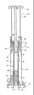
Fig. 8 is a longitudinal cross-sectional view of the delivery device, taken
along
line 8-8 of Fig 1;
Fig. 9 is a longitudinal cross-sectional view similar to that of Fig. 8 as the
delivery
device is in process of having its syringe advanced during needle insertion;
Fig. 10 is a longitudinal cross-sectional view similar to that of Fig. 9 as
the
delivery device is in the process of having its contained medication injected
through the
inserted syringe needle;
Fig. 11 is a longitudinal cross-sectional view similar to that of Fig. 9 as
the
delivery device is near the end of its contained medication injection and at
which time the
retracting assembly has been shifted to an operational state;
Fig. 12 is a longitudinal cross-sectional view similar to that of Fig. 9 after
the
delivery device contents have been administered and before a manual plunging
force has
been removed from the plunger;
Fig. 13 is a longitudinal cross-sectional view similar to that of Fig. 9, but
taken
along line 13-13 of Fig. 1, after the manual plunging force has been removed
from the
plunger and during the retraction of the syringe by operation of the
retracting assembly;
and
Fig. 14 is a longitudinal cross-sectional view similar to that of Fig. 13 of
the
device in a final state after the syringe has been fully retracted and locked
against further
use.
CA 02753812 2013-11-27
,
-5--
Corresponding reference characters indicate corresponding parts throughout the
several views. Although the drawings represent an embodiment of the present
invention,
the drawings are not necessarily to scale, and certain features may be
exaggerated or
omitted in some of the drawings in order to better illustrate and explain the
present
invention.
DETAILED DESCRIPTION OF THE INVENTION
Referring now to Figs. 1-14, there is shown one embodiment of a pharmaceutical
delivery device of the present invention. The delivery device, generally
designated 20, is
a single use delivery device. Device 20 is based on a standard, prefilled
syringe as
primary containment, but may be adapted for other syringes. Device 20 is
delivered
ready to use, and is operable to provide a single, fixed dose delivery of its
prefilled
medication. The device is functionally similar in many respects to those
disclosed in
W02007/047200.
Any directional references in this detailed description with respect to the
Figures,
such as up or down, or top or bottom, or front and side, are intended for
convenience of
description, and by itself does not limit the present invention or any of its
components to
any particular positional or spatial orientation.
Delivery device 20 is designed to allow a user, with one hand on the device,
to
comfortably position the device on the skin at a pre-selected site for
injection. After such
siting, typically the user's other hand can be used to manually drive down the
device
plunger to cause needle insertion and drug delivery. When the driving plunging
force is
removed from the device plunger, the syringe needle automatically retracts
within the
device housing, and is automatically locked therein.
Delivery device 20 includes an outer housing, generally designated 22, having
a
distal end 24 and a proximal end 26. As used herein, distal and proximal refer
to axial
CA 02753812 2011-08-26
WO 2010/104779
PCT/US2010/026503
-6-
locations on the delivery device relative to an injection site when the device
is oriented
for use at such site, whereby, for example, proximal end of the housing refers
to the
housing end that is closest to such injection site.
The exterior periphery of outer housing 22 is sized, shaped and constructed of
materials to facilitate being gripped within one hand by a user or a caregiver
during site
selection and injection. Outer housing 22 is shown formed by a main body 28,
an end
plate 30, and a body collar 32 that are fixedly attached together. Collar 32
has an annular
portion 34 from which depends a pair of latching prongs 36 that snap fit
through openings
38 in main body 28 during assembly to fixedly secure collar 32 with body 28.
Collar 32
may be made of a suitable material, such as ABS plastic, to provide
stabilization with
limited resistance to the plunger as it guides its sliding motion during use.
Body 28 and
plate 30 may be formed of one or more materials, including clear plastics and
with soft
touch covering particularly on its grippable portions, and each may be
assembled from
more than just the single injection molded part shown.
Plate 30 includes a skin-contacting surface 40 and an upper surface 42, and is
formed with a central aperture 44 for needle passage and three arcuate slots
46. A plastic
needle cap 50 designed to be removed manually by a person before injection
includes a
base 52 with a knurled periphery, and an upstanding sleeve 54 that fits
through aperture
44. Three curved cams 56 that fit within slots 46 are disposed outward of
sleeve 54 and
facilitate cap removal. The base of each cam 56 is also formed with an outward
facing
snap feature 58 that, once inserted through the slots 46, snap fits outward to
releasably
engage plate surface 42 to keep cap 50 in place on the device 20 until
purposefully
removed.
Sleeve 54 includes at its distal end a pair of diametrically opposed prongs
60.
Sleeve internal hollow 62 accommodates the injection needle 72 of the syringe
70, as well
CA 02753812 2011-08-26
WO 2010/104779
PCT/US2010/026503
-7-
as elastomeric sealing shield 74 and rigid cover 76 that effectively serve as
part of the
cap. When cap 50 is removed from the configuration shown in Fig.1, latching
hooks on
prongs 60 engage the distal surface of rigid cover 76 and serve to remove the
shield 74
and cover 76 from the needle 72 to expose the needle tip within the housing
for
subsequent use.
Syringe 70 is of suitable known design and includes barrel 80 to which needle
72
is mounted, and an elastomeric stopper or piston 82 that slidably seals the
distal end of
the medicine filled interior 84.
A syringe carriage 90 of device 20 is disposed within outer housing 22.
Carriage
90 is rotatably fixed relative to outer housing 22 such as further described
below, but is
selectively axially movable therein to allow for device functionality.
Carriage 90 is
formed in one piece from a suitable plastic material and includes a tubular
body 92
haying a distal end 94 which serves as a seat upon which fits the flange 86 of
the syringe
barrel 80 which projects at its distal end. Syringe barrel 80 fits within an
interior hollow
93 of body 92, and a pair of not shown, longitudinally extending ribs that are
formed on
the carriage body interior surface that defines hollow 93 provide a friction
fit that keeps
the syringe 80 in a rotationally and axially fixed orientation relative to the
carriage 90.
Other substitutable or additional securing means, such as a clip at the top of
the carriage,
may be used to keep the cartridge and syringe together.
At its distal end, tubular body 92 includes a pair of guide keys or wings 96
that are
integrally formed with and project radially outward from the outer periphery
of body 92.
Staging nubs 98 are disposed on the carriage body periphery between keys 96.
Nubs 98
are integrally formed with and project radially outward from body 92 a
distance less than
keys 96. Nubs 98 serve as push surfaces against which an axial force can be
applied by
CA 02753812 2011-08-26
WO 2010/104779
PCT/US2010/026503
-8-
the plunger to carriage 90 to drive the carriage and held syringe proximally
to cause
needle insertion.
Projecting from its proximal end, carriage body 92 includes a pair of axially
extending, flexible legs 100 that are diametrically disposed. A detent 102 is
formed on the
outer region of each leg 100 at its proximal end. The inner face of each
proximal leg end
includes a slight beveling or ramping that cooperates with a beveled edge of
cap sleeve
54 to bend legs 100 outward during assembly.
Carriage body 92 includes a pair of nubs 104 formed on its exterior at a one
hundred eighty degree angular spacing and near the proximal end of body 92.
Nubs 104
project radially outward and serve as retraction lock features that cooperate
with
complementary features of the biasing member retaining collar to lock the
syringe in a
retracted position within the housing after the syringe has been retracted
automatically
following use.
Carriage body 92 also includes a single resilient capture or latching tang 106
disposed distally of and angularly offset from latching nubs 104. Tang 106
projects at an
angle from body 92 in a direction downward and radially outward therefrom.
Tang 106,
due to its resilient construction, is able to bend inward and then snap back
outward into a
locking arrangement during passage of a plunger element during the injection
process.
Housing body 28 includes an interior hollow 110 defined by a surface that
includes a pair of diametrically opposed, longitudinally extending ribs shown
in dashed
lines at 112 in Fig.4. Ribs 112 serve as keys that guide the longitudinal
motion of the
plunger assembly. The proximal ends of ribs 112 are indicated at 113.
Angularly spaced
from ribs 112 is a pair of diametrically opposed staging ribs 114 that
cooperate with the
plunger assembly. Each rib 114 includes a bar-shaped main section 115, a
sloping
surface or ramp 118 leading to the distal end of section 115, and ramp 120 at
the proximal
CA 02753812 2011-08-26
WO 2010/104779
PCT/US2010/026503
-9-
end of section 115. Ramps 118 provides a short and smooth storage of energy
prior to
syringe movement, and ramps 120 in effect cause the release of the carriage
from direct
advancement by the plunger. The ramps 118 and 120 may be of slopes selected by
the
designer to achieve the proper feel and operation of the pen. Suitable slopes
include
about forty-five degrees, and a larger slope for ramp 120 may be desirable to
provide a
more precise release of the plunger that defines a moment of unstaging for the
shown
apparatus.
The plunger of device 20 is generally designated 130 and is manually operable
by
a user to affect operation of the device. Plunger 130 is shown formed from
plastic
molded parts including a plunger sleeve 132, a plunger rod or stem 134, and a
plunger
cap 136 all rigidly interconnected during manufacturing assembly. Plunger
sleeve 132 is
disposed around and concentrically with stem 134 in a radially spaced apart
relationship
to define an annular gap in which freely fits portions of the carriage and
syringe. The
distal surface 138 of cap 136 is intended as the surface to be directly
pressed on by a user
to plunge the plunger. Plunger stem 134 includes a distal end 140 that is
press fit, and
then further secured thereat with a UV-cured adhesive, within an annular lip
142 of the
proximal surface of cap 136. The plunger stem and cap may be differently
attached, such
as via a snap fit. The proximal end 145 of plunger stem 134 is sized to fit
freely within
syringe barrel 80 for a direct pushing engagement of syringe piston 82.
Plunger sleeve 132 has a cylindrical tubular body 150 including a distal end
152
that is press fit, and then further secured thereat with a UV-cured adhesive,
within a
second annular lip 146 of cap 136. The plunger sleeve and cap may be
differently
attached, such as via a snap fit. A circumferential, beveled shoulder or lip
156 extends
around the proximal end of sleeve 132. A first pair of diametrically opposed
and
longitudinally extending slots or notches 158 in lip 156 accommodate housing
ribs 112
CA 02753812 2011-08-26
WO 2010/104779
PCT/US2010/026503
-10-
and serve as guide slots whereby rotational motion of the plunger sleeve 132
relative to
the housing 28 is prevented at all times throughout the plunger travel as it
moves
longitudinally within the housing during use. A second pair of diametrically
opposed,
longitudinal slots 159 in lip 156 that are angularly spaced from lip slots 158
serve as
clearance slots allowing for passage of staging ribs 114. Lip 156 prevents
improper
withdrawal of the plunger from the housing by the user prior to injection by
an
interference with body collar 32.
The interior surface of plunger sleeve 132 is provided with a pair of
longitudinally
extending guide grooves that are not shown. The guide grooves slidably receive
carriage
keys 96 to effectively rotatably lock the carriage 90 and plunger element 130
together at
all times while allowing relative axial motion as further described below. As
shown in
dashed lines at 160 in Fig. 4, the interior surface of plunger sleeve 132 also
includes a
pair of nubs that are diametrically opposed. Nubs 160 serve as latching
features that
cooperate with complementary features of the biasing member retaining collar
to
releasable latch together the biasing member retaining collar described below
and the
carriage 90 during manufacturing assembly.
A pair of diametrically opposed resilient prongs 165 are formed in plunger
sleeve
132 near its proximal end. Each of prongs 165 includes at its proximal end an
inwardly
projecting tab 166 seen in Fig. 2, and a radially outwardly projecting tab
168. Tabs 166
are structured to drivingly engage carriage staging nubs 98 when the prongs
165 are bent
inward when tabs 168 slide along housing ribs 114 during the plunging of
plunger 130
relative to the housing 22 from the ready position shown in Fig. 1.
The automatic syringe retraction feature of device 20 uses a biasing member
retaining collar, generally designated 170, that is further shown in Figs. 6A-
6F. Collar
170 fits freely around the carriage 90 concentrically therewith so as to be
moveable
CA 02753812 2011-08-26
WO 2010/104779
PCT/US2010/026503
-11-
axially and rotatably relative to the carriage until it lockingly engages the
carriage after
syringe retraction following injection. Biasing member retaining collar 170
includes a
ring-shaped body 172 that extends completely around carriage 90 when device 20
is
assembled. Collar body 172 includes a pair of longitudinally extending notches
174
formed in its outer periphery which accommodate housing ribs 112. Small
longitudinal
ribs 175 shown flanking each of notches 174 are provided for tolerance
control. Collar
body 172 includes a second pair of longitudinally extending notches 176 that
are
angularly spaced from notches 174 around the outer periphery and serve as
clearance
slots allowing for passage of staging ribs 114. A pair of notches each
including ramp
surface 180 and an enlarged seating surface 182 are formed in the lower face
177 of body
172 at a one-hundred and eighty degree interval. Within the interior of collar
170, a
generally annular, proximal facing surface 178 of body 172 serves as a
physical stop for
abutment by the flats 101 on the distal faces of the carriage detents 102
during syringe
retraction.
The upper face 185 of body 172 transitions to an upstanding tube portion 187
that
is interrupted along its circumference by opposing pairs of open ended slots
189 that
define resilient locking tangs 192 that flex outward and then snap inward as
described
below to perform a carriage locking. Diametrically opposed notches 195 in tube
portion
187 are provided to allow passage of carriage guide keys 96 during
manufacturing
assembly. Two axially oriented ribs 194 protrude from the interior surface of
collar 170
along its axial height. Ribs 194 serve to maintain a centering of the device
components.
Along the distal edge of tube portion, a pair of plunger latching features is
formed spaced
apart at a one hundred eighty degree interval. Two latching features are
preferred to
balance forces, but different numbers of such features, including as few as a
single such
feature, may be employed. Each latching feature includes a lip, generally
designated 200,
CA 02753812 2011-08-26
WO 2010/104779
PCT/US2010/026503
-12-
which projects radially outward of so as to overhang an inwardly recessed
region 196 of
tube portion 187. Lip 200 includes a retaining segment 202 that extends in a
circumferential direction, as well as a short catch segment 204 and an end
wall segment
206 that depend from retaining segment 202. Lip 200 is sized and configured
with the
plunger nub 160 so as to fit thereover, with the nub 160 in contact with lip
200, and more
particularly the proximal surface of retaining segment 202, and with the nub
projecting
toward recessed region 196 within the space axially below lip segment 202 and
angularly
between the wall segment 206 and catch segment 204. In such an arrangement,
the collar
170 is releaseably latched with the plunger. Recessed region 196 provides
extra space in
the shown embodiment to fit nub 160 and allow for more material in the radial
direction
and therefore more robust lip engagement. In addition, the wall defining the
back of
recessed region 196, by virtue of its proximity to the outer surface of
carriage body 92,
prevents lip 200 from flexing radially inwardly during device storage or
operation. Wall
segment 206 serves to add rigidity to lip 200, and catch segment 204 provides
a detenting
feature for the nub which is useful to maintain component alignment during
manufacturing assembly.
A biasing member acting to force plunger 130 and collar 170 apart is part of
the
automatic syringe retraction feature of device 20. In the shown embodiment,
the biasing
member is in the form of a preloaded element captured between the plunger and
collar.
The biasing member is a coiled metal compression spring 210 that fits around
collar tube
portion 187. The distal end 212 of spring 210 abuts the underside of plunger
sleeve lip
156 and the proximal end 214 of spring 210 abuts the upper face 185 of collar
body 172.
When plunger 130 and collar 170 are latched together when device 20 is in a
ready state such as shown in Figs. 1 and 8, which latching results form the
engagement of
collar lips 200 and plunger nubs 160, spring 210 is captured in a compressed
state, and
CA 02753812 2011-08-26
WO 2010/104779
PCT/US2010/026503
-13-
collar 170 and therefore captured spring 210 are carried with the plunger to
move
identically therto. When plunger 130 and collar 170 are rotated relative to
one another so
as to release the latching feature and unlatch these components as further
described
below, the retracting assembly is operational and spring 210 tends to expand
to force the
plunger 130 and collar 170 axially apart. Spring 210 is selected by the
designer to
provide enough force to overcome the detenting force keeping the syringe
carriage with
the housing end plate and then to properly retract the carriage and held
syringe
automatically when the user removes her hand from the plunger, or otherwise
stops
applying any force to the plunger, at the end of injection. The spring force
is less than a
normal plunging force expected to be applied by a user so as to not cause the
plunger to
move distally unexpectedly as the user continues to plunge it until injection
is complete.
One suitable spring 210 applies a maximum returning force on the plunger of
about 1.1
pounds.
The syringe retraction feature also uses an unlatching element axially and
rotatably fixed in the housing which engages collar 170 so as to rotate the
collar 170 out
of latching engagement with the plunger 130. In the shown embodiment, the
unlatching
element is provided in the form of a pair of upstanding tabs 220 formed
integrally with
end plate 30. In alternate embodiment, the function of the tabs may be
differently
provided for, such as by ears that fixedly project inward from the interior
surface of
housing body 28 for engagement with the collar. Tabs 220 include radially
oriented top
surfaces 222 that are slidably engaged by collar ramp surfaces180 and that fit
against
collar seating surfaces 182. The abutment of tab surfaces 222 by the ends of
carriage legs
100 when the legs are bent outward by cap sleeve 54 frustrates the proximal
plunger
motion of an injection attempt prior to cap removal. The inward edge 224 of
each top
surface 222 is beveled to lead to a tab side surface 226 that is provided with
a detent ramp
CA 02753812 2011-08-26
WO 2010/104779
PCT/US2010/026503
-14-
228 designed to releasable engage carriage leg detents 102. Two support
members 230
that are formed integrally with the end plate extend between tabs 220 and
which ring
aperture 38 provide rigidity to tabs 220. Ledges 232 formed on support members
230
flank detent ramp 228 and serve as a stop surface against which abut carriage
leg detents
102 to halt carriage advancement. Ledges 232 do not extend below ramp 228 to
facilitate
ramp molding. The height of tabs 220 is selected during design to unlatch the
collar 170
from the plunger 130, thereby permitting the needle retraction once the
plunger driving
force is removed, at a point which guarantees that the entire desired contents
of the
syringe, within tolerance restrictions, have been delivered. At such point,
typically the
syringe piston is slightly spaced from the bottom of the syringe barrel, and
the force and
momentum of normal manual plunging action is believed to cause users to
typically
bottom out the syringe piston travel before force is removed from the plunger
that allows
the automatic retraction feature to cause the plunger to travel distally
The collar and the device components which are physically engaged by the
collar
are made of materials chosen to account for the sliding motion therebetween.
For
example, in the shown embodiment, collar 32 is formed in one piece out of a
low friction
material, such as an ABS plastic molded with a lubricating additive, and the
plunger
sleeve 130 and end plate 30 are molded from one or more complementary plastics
such as
a clear ABS.
The construction of device 20 will be further understood in view of the
following
explanation of an exemplary operation. The user will typically be provided
with a device
in its capped, ready state as shown in Figs. 1 and 8. After the user removes
the cap 50
and therefore the held shield 74 and cover 76, which removal leaves the
injection needle
72 uncovered but entirely within the confines of body 28, the device is
manually placed
with end plate 30 against the injection site. When a user then manually
applies a
CA 02753812 2011-08-26
WO 2010/104779
PCT/US2010/026503
-15-
plunging force directly on plunger cap 136, plunger 130 starts to move
proximally,
causing tabs 166 to abut nubs 98 due to the inward motion of the prongs 165
resulting
from the sliding engagement of tabs 168 with housing ribs 114. A further
manual
plunging of plunger 130 starts to drive carriage 90 and its held syringe 70,
as well as
carries collar 170 and the captured spring 210, simultaneously, and in an
equal amount,
proximally as carriage legs 100 bend inward as detents 102 slide over edges
224 and
along tab surface 226. As the manual plunging continues, causing the tip of
injection
needle 72 to pass through aperture 44 and into the user at the injection site,
the carriage
90 continues to move proximally until detents 102 snap over detent ramp 228,
providing
an audible and tactile indication of needle insertion, at which time the
plunger prongs 165
resiliently splay out of engagement with nubs 98 due to tabs 168 reaching the
proximal
end of ribs 114. At this point, carriage advancement due to direct engagement
by the
plunger sleeve has been halted and the syringe needle is effectively inserted
for an
injection, and the device is configured as shown in Fig. 9.
As a user continues to manually plunge the plunger 130 proximally, piston 82
is
forced by plunger rod 134 to move proximally within the axially stationary
syringe,
forcing the medicine contained with the syringe out through injection needle
72. During
this piston motion, a very small, such as about 0.5 mm, additional carriage
and syringe
advancement in the proximal direction relative to the housing is typical due
to frictional
and/or hydraulic forces, which small advancement is physically halted by the
carriage leg
detents 102 abutting housing plate ledges 232. Fig. 10 shows device 20 during
medication injection at a point before plunger sleeve tab 166 begins camming
radially
inward carriage tang 106. Collar 170 remains latched with plunger element 130
by the
engagement of lip segments 202 with nubs 160, only one of which is visible in
Fig. 10
due to the cut line used in the view. Collar 170 is also still in a
rotationally fixed
CA 02753812 2011-08-26
WO 2010/104779
PCT/US2010/026503
-16-
arrangement with the housing 22 as its guide notches 174 still fit over
housing ribs 112.
Collar 170 has yet to reach a point at which it engages end plate tabs 220.
Fig. 11 shows
device 20 during medication injection at a subsequent point after plunger
sleeve tab 166
has passed proximally the tang 106, which tang has resiliently returned to its
outward
extending arrangement. During the plunger movement from its position in Fig.
10 to Fig.
11, collar 170 has been carried axially therewith such that notches 174 pass
the ends 113
of ribs 112, freeing one restraint against the collar rotating in the housing.
In addition,
collar 170 has been forcibly rotated from a first angular orientation within
the housing
due to its cam engagement with the plate tabs 220, so as to unlatch collar 170
from the
plunger 130 to enable the retracting assembly to function. More specifically,
as collar
170 has been so moved downward, ramp surfaces 180 contact tab top surfaces
222, and
collar 170 is rotated as collar surfaces 180 slide along surfaces tab 222 at
which the collar
seating surfaces 182 reach and seat on tab top surfaces 222 that serve as
physical stops to
further proximal motion of the collar. At this time, in which collar 170 is at
a second
angular orientation within the housing where the collar lip segments 202 and
catch
segments 204 have been rotated over and completely clear of plunger nubs 160
so as to
unlatch the collar and the sleeve thereby freeing the retraction spring 210 to
act
therebetween, the immediate expansion of which spring is prevented by the
continued
force being applied by the user to the plunger. This unlatching occurs just
slightly before,
as a function of the mechanical tolerance stack as previously described, the
plunger 130
has reached the end of its stroke, shown in Fig. 12, at which the piston 82
has bottomed
out within the syringe barrel 80 and halts all further ability of plunger 130
to be advanced
proximally by the user, which bottoming out indicates to the user that
injection is
complete. Spring 210 is chosen to have sufficient clearance within its coils
to allow for
CA 02753812 2011-08-26
WO 2010/104779
PCT/US2010/026503
-17-
the small compression associated with this last bit of proximal movement the
plunger
sleeve 130 has relative to collar 170.
When a user, now aware that injection is complete, then stops applying a
proximal
force to plunger 130, the retracting assembly serves to retract the syringe
needle within
the housing automatically without further user input. Specifically, as spring
210 expands
it drives plunger 130 distally relative to the housing, during which motion
plunger tab
166 abuts carriage tang 106, causing carriage 90 and its held syringe 70 to be
shifted
distally within housing 28 with the plunger. As carriage 90 and syringe 70 are
pulled
upward by plunger 130, carriage nubs 104 pass collar tangs 192, which tangs
bend
outward resiliently when in contact with nubs 104 and which tangs then snap
radially
inward to a locking arrangement positioned proximally of the nubs 104. The
collar 170 is
prevented from being pulled upward due to the interference of housing rib ends
113 with
the upper face 185 of collar body 172. At this point device 20 is arranged as
shown in
Fig. 13, in which arrangement syringe 70 and its needle 72 are protectively
locked from
proximal motion within the housing in that a direct physical abutment of the
syringe
carriage nubs 104 with the collar tangs 192 prevents proximal plunging of the
syringe
needle from the housing. Spring 210 continues to further retract the plunger
and the
captured carriage and held syringe into housing until the flats 101 of the
carriage legs
abut and are physically stopped by the collar, distal motion of which collar
is prevented
by rib ends 113, at which time device 20 is configured as shown in Fig. 14
ready to be
disposed of properly by the user.
While this invention has been shown and described as having preferred designs,
the present invention may be modified within the spirit and scope of this
disclosure. This
application is therefore intended to cover any variations, uses or adaptations
of the
invention using its general principles. Further, this application is intended
to cover such
CA 02753812 2011-08-26
WO 2010/104779
PCT/US2010/026503
-18-
departures from the present disclosure as come within known or customary
practice in the
art to which this invention pertains.