Note: Descriptions are shown in the official language in which they were submitted.
CA 02753939 2011-08-29
WO 2010/100241 PCT/EP2010/052786
Description
DRUG DELIVERY DEVICE WITH RETRACTABLE NEEDLE
The invention relates to a drug delivery device comprising a needle.
One problem of existing drug delivery devices, for example of a syringe,
especially
safety syringes which have retractable needles, is to have a needle which is
fixed and
does not move with respect to the body of the syringe during the use of the
syringe but
which can be drawn back into the body of the safety syringe after the use of
the
syringe. So the needle of the drug delivery device has to be formed in a
special way
and also has to be arranged in a special way inside the body of the device so
that it is
fixed during use but movable with respect to the body of the device after use
of the
drug delivery device.
Most of the common safety syringes with a retractable needle comprise a needle
which
comprises an arrangement at the inner end which is formed from a material
which is
different to the needle and which may be formed in complicated geometrical
ways to
snap mechanically, for example, into other parts of the syringe in a key-lock-
mechanism so that the needle arrangement could be later drawn back into the
body of
the syringe.
One embodiment of the invention is directed to a drug delivery device
comprising a
needle with a distal end and a proximal end comprises an inner surface forming
a
channel,
an outer surface and a first salient located on the outer surface.
The drug delivery device, which can be a syringe, preferably a safety syringe,
comprises a needle, wherein the needle itself has a first salient which is
located on the
outer surface of the needle. The salient could be, for example, a bulge at the
surface,
which can have any geometric form, for example hemispherical. Thus it is not
necessary to form an additional element around the needle made of another
material
CA 02753939 2011-08-29
WO 2010/100241 PCT/EP2010/052786
2
which can be used to connect the needle with other parts of the syringe, like
for
example the proximal end of the syringe body or the plunger of the syringe.
The
connection between the proximal end of the body of the syringe is necessary to
locate
the needle during the use of the syringe. The connection between the plunger
of the
syringe and the needle is necessary to draw back the needle into the body unit
after
the use of the syringe.
In another embodiment, the needle comprises a second salient located on the
outer
surface between the proximal end and the first salient.
Both of the salients, the first and the second one, can be used on one hand to
fix the
needle, for example in the body unit of the drug delivery device for the time
when the
device is used. On the other hand one or both of the salients can be used to
connect
the needle with another part of the drug delivery device without any
additional
elements at the outside of the needle, for example coatings or overmoulded
features,
being necessary.
In another embodiment, the first and second salients comprise the same
material as
the rest of the needle.
If the two salients are made of the same material as the rest of the needle,
the needle
and the salients could be formed in the same production step. There are no
further
production steps necessary to arrange salients at the outside of the needle.
This keeps
the number of production steps to manufacture the drug delivery device low.
Another
advantage is that the salients are strongly connected to the needle. The
salient may
not break away as easily as when the salients are formed around the needle in
a
separate production step.
The material, the needle and therefore the first and the second salient could
be made
of, for example, a metal or an alloy.
CA 02753939 2011-08-29
WO 2010/100241 PCT/EP2010/052786
3
In another embodiment, the salients are provided by means of an additional
element
around the needle made of another material. Although this is an additional
material
andmanufacturing step there may be circumstances where this is more
straightforward
than forming the salients from the needle material. In this embodiment the
invention
retains the advantage, compared to existing safety syringe devices with
retractable
needles, that the salients and the needle release mechanism are mechanically
simple,
comprising only the interaction of a seal and the salient or salients.
In another embodiment, the first salient has a circumferential form
surrounding the
needle.
This means that the first salient forms a ring around the outer surface of the
needle.
In another embodiment, the second salient has a circumferential form
surrounding the
needle.
This means that the second salient forms a ring around the outer surface of
the
needle.
In another embodiment, both of the salients, the first and the second, have a
circumferential form surrounding the needle.
If the salient has a circumferential form with respect to the needle, the
needle could be
better fixed inside the body so that it cannot slip out of the fixing in any
direction. Also
the connection of the needle with other parts of the device is stronger and
safer
compared to a salient which is located only on one point or one side of the
needle.
In another embodiment, the first and the second salients are formed such that
their
outer diameter continuously increases along the channel up to a maximum and,
beyond the maximum, continuously decreases.
CA 02753939 2011-08-29
WO 2010/100241 PCT/EP2010/052786
4
If the salients are formed in this way, the needle could be more easily
"unlocked" from
a fixing, which can be a seal, for example, by pushing the seal over the
salient out of
its "locking" position into an "unlock" position. If the seal is in the
"unlock" position the
needle could be moved after the use of the drug delivery device with respect
to the
body of the device. Also the needle could be more easily connected to another
part,
the plunger for example, of the drug delivery device.
In another embodiment, the diameter of the channel is constant in the area of
the first
and the second salient.
The advantage of a constant diameter of the channel over the whole needle is
that if,
for example, a liquid, is pressed through the needle, the liquid always moves
the same
distance in the channel for the same volume of liquid which is pressed into
the
proximal end of the needle. Therefore the liquid could be released by the drug
delivery
device in constant dosages.
In another embodiment, the drug delivery device additionally comprises a body
unit
having a first opening and a second opening, a plunger arranged such that its
outer
end is positioned outside the body unit, and its inner end is positioned
within the body
unit, wherein the plunger is movable in the distal direction with respect to
the body unit,
wherein the needle being arranged such that the proximal end and the first and
the
second salient are positioned within the body unit.
The plunger which is movable with respect to the body unit can be used, on the
one
hand, to press a liquid which could be, for example, inside the body unit of
the drug
delivery device through the needle to the distal end of the needle. On the
other hand,
the plunger could be used after the use of the drug delivery device to get
into
connection with the needle and to draw back the needle into the body unit
after the use
of the drug delivery device. The needle with the first and the second salient,
which both
are positioned inside the body unit, could be fixed during the use of the drug
delivery
device by means of the first and the second salient and furthermore could be
connected over the first and/or the second salient with the plunger to draw
back the
CA 02753939 2011-08-29
WO 2010/100241 PCT/EP2010/052786
needle into the body unit after the use of the drug delivery device to avoid
the risk of
injury, for example, at the distal end of the needle.
In another embodiment, a seal is arranged within the body unit around the
needle such
5 that it is located between the first and the second salient.
The seal which is located between the first and the second salient can fix the
needle in
the body unit, such that the needle does not move with respect to the body
unit. The
seal itself is fixed between the needle, between the first and the second
salient, on one
side and the body unit on the other side. Preferably, the seal has a
circumferential form
with respect to the needle.
In another embodiment the seal comprises a groove at the surface faced to the
body
unit and the groove has a circumferential form.
The groove can be used to fix the seal in its positon, for example by a
salient at the
inner side of the body unit.
In another embodiment, the seal fixes the needle such that it cannot be moved
relative
to the body unit.
In another embodiment, a void is located around the needle between the seal
and the
second opening of the body unit, wherein the void is formed such that it can
at least
partly house the seal.
The void which is located in the body unit is able to at least partly house
the seal,
preferably the whole seal. The void has preferably a circumferential form with
respect
to the needle.
In another embodiment the inner end of the plunger is configured to push the
seal to a
position where the seal releases the needle.
CA 02753939 2011-08-29
WO 2010/100241 PCT/EP2010/052786
6
By means of moving the plunger in the distal direction, the seal can be pushed
from
the inner end of the plunger such that at least part of the seal or the whole
seal is
located in the void after being pushed. Thereby, the seal has to move over the
first
salient, which is a mechanical resistance with respect to the distal movement
of the
seal. If the seal is located in the void, it is fixed by the first salient so
that it cannot
move in the proximal direction back into the position between the first and
the second
salient. When the seal is located in the void it releases the needle.
In another embodiment, the needle is movable in the proximal direction with
respect to
the body unit when the seal is located on the first salient or between the
first salient
and the second opening of the body unit.
For example, after pushing the seal with the inner end of the plunger on or
over the
first salient, the seal is situated on the first salient or between the first
salient and the
second opening of the body unit. After pushing the seal on or over the first
salient, the
needle is not fixed as strongly as before and can now be moved in the proximal
direction with respect to the body unit. Preferably, the needle cannot move in
the distal
direction because of the first salient which is now located in or in proximal
direction to
the seal.
In another embodiment, the inner end of the plunger is configured to be
engaged with
the first and/or the second salient when the plunger is pushed to a certain
position with
respect to the needle.
The inner end of the plunger can be configured to be engaged with one of the
two
salients or with both salients at the same time. When the plunger is pushed in
the
distal direction, for example to push the seal into the void, the inner end of
the plunger
can is engaged with one or both salients such that the needle is connected to
the
plunger. If the plunger is now retracted into the proximal direction, the
needle is also
retracted into the proximal direction and therefore into the body unit of the
drug
delivery device.
CA 02753939 2011-08-29
WO 2010/100241 PCT/EP2010/052786
7
In another embodiment, the needle is formed such that it can at least be
partly
retracted into the body unit after being engaged with the plunger.
Formed means, on one hand, that the needle is able to be engaged with the
inner end
of the plunger and, on the other hand, that it can be moved into the proximal
direction,
for example, because there is no salient on the distal side of the second
opening of the
body unit.
In another embodiment, the drug delivery device comprises a boss which is
located at
the inner surface of the body unit and the boss has a circumferential form
surrounding
the second opening.
In another embodiment, the seal is moveable onto the boss, where the seal
releases
the needle.
In another embodiment the drug delivery device comprises a medicament. The
medicament could be pre-filled in a cartridge or, if the drug delivery device
is designed
as a syringe, pre-filled in the syringe.
The term õmedicament", as used herein, means a pharmaceutical formulation
containing at least one pharmaceutically active compound,
wherein in one embodiment the pharmaceutically active compound has a molecular
weight up to 1500 Da and/or is a peptide, a proteine, a polysaccharide, a
vaccine, a
DNA, a RNA, a antibody, an enzyme, an antibody, a hormone or an
oligonucleotide, or
a mixture of the above-mentioned pharmaceutically active compound,
wherein in a further embodiment the pharmaceutically active compound is useful
for
the treatment and/or prophylaxis of diabetes mellitus or complications
associated with
diabetes mellitus such as diabetic retinopathy, thromboembolism disorders such
as
deep vein or pulmonary thromboembolism, acute coronary syndrome (ACS), angina,
CA 02753939 2011-08-29
WO 2010/100241 PCT/EP2010/052786
8
myocardial infarction, cancer, macular degeneration, inflammation, hay fever,
atherosclerosis and/or rheumatoid arthritis,
wherein in a further embodiment the pharmaceutically active compound comprises
at
least one peptide for the treatment and/or prophylaxis of diabetes mellitus or
complications associated with diabetes mellitus such as diabetic retinopathy,
wherein in a further embodiment the pharmaceutically active compound comprises
at
least one human insulin or a human insulin analogue or derivative, glucagon-
like
peptide (GLP-1) or an analogue or derivative thereof, or exedin-3 or exedin-4
or an
analogue or derivative of exedin-3 or exedin-4.
Insulin analogues are for example Gly(A21), Arg(B31), Arg(B32) human insulin;
Lys(B3), Glu(B29) human insulin; Lys(B28), Pro(B29) human insulin; Asp(B28)
human
insulin; human insulin, wherein proline in position B28 is replaced by Asp,
Lys, Leu,
Val or Ala and wherein in position B29 Lys may be replaced by Pro; Ala(B26)
human
insulin; Des(B28-B30) human insulin; Des(B27) human insulin and Des(B30) human
insulin.
Insulin derivates are for example B29-N-myristoyl-des(B30) human insulin; B29-
N-
palmitoyl-des(B30) human insulin; B29-N-myristoyl human insulin; B29-N-
palmitoyl
human insulin; B28-N-myristoyl LysB28ProB29 human insulin; B28-N-palmitoyl-
LysB28ProB29 human insulin; B30-N-myristoyl-ThrB29LysB30 human insulin; B30-N-
palmitoyl- ThrB29LysB30 human insulin; B29-N-(N-palmitoyl-Y-glutamyl)-des(B30)
human insulin; B29-N-(N-lithocholyl-Y-glutamyl)-des(B30) human insulin; B29-N-
(w-
carboxyheptadecanoyl)-des(B30) human insulin and B29-N-(w-
carboxyheptadecanoyl)
human insulin.
Exendin-4 for example means Exendin-4(1-39), a peptide of the sequence H-His-
Gly-
Glu-Gly-Thr-Phe-Thr-Ser-Asp-Leu-Ser-Lys-Gln-Met-Glu-Glu-Glu-Ala-Val-Arg-Leu-
Phe-
Ile-Glu-Trp-Leu-Lys-Asn-Gly-Gly-Pro-Ser-Ser-Gly-Ala-Pro-Pro-Pro-Ser-N H2.
CA 02753939 2011-08-29
WO 2010/100241 PCT/EP2010/052786
9
Exendin-4 derivatives are for example selected from the following list of
compounds:
H-(Lys)4-des Pro36, des Pro37 Exendin-4(1-39)-NH2,
H-(Lys)5-des Pro36, des Pro37 Exendin-4(1-39)-NH2,
des Pro36 [Asp28] Exendin-4(1-39),
des Pro36 [IsoAsp28] Exendin-4(1-39),
des Pro36 [Met(O)14, Asp28] Exendin-4(1-39),
des Pro36 [Met(O)14, IsoAsp28] Exendin-4(1-39),
des Pro36 [Trp(02)25, Asp28] Exendin-4(1-39),
des Pro36 [Trp(02)25, IsoAsp28] Exendin-4(1-39),
des Pro36 [Met(O)14 Trp(02)25, Asp28] Exendin-4(1-39),
des Pro36 [Met(O)14 Trp(02)25, IsoAsp28] Exendin-4(1-39); or
des Pro36 [Asp28] Exendin-4(1-39),
des Pro36 [IsoAsp28] Exendin-4(1-39),
des Pro36 [Met(O)14, Asp28] Exendin-4(1-39),
des Pro36 [Met(O)14, IsoAsp28] Exendin-4(1-39),
des Pro36 [Trp(02)25, Asp28] Exendin-4(1-39),
des Pro36 [Trp(02)25, IsoAsp28] Exendin-4(1-39),
des Pro36 [Met(O)14 Trp(02)25, Asp28] Exendin-4(1-39),
des Pro36 [Met(O)14 Trp(02)25, IsoAsp28] Exendin-4(1-39),
wherein the group -Lys6-NH2 may be bound to the C-terminus of the Exendin-4
derivative;
or an Exendin-4 derivative of the sequence
H-(Lys)6-des Pro36 [Asp28] Exendin-4(1-39)-Lys6-NH2,
des Asp28 Pro36, Pro37, Pro38Exendin-4(1-39)-NH2,
H-(Lys)6-des Pro36, Pro38 [Asp28] Exendin-4(1-39)-NH2,
H-Asn-(Glu)5des Pro36, Pro37, Pro38 [Asp28] Exendin-4(1-39)-NH2,
des Pro36, Pro37, Pro38 [Asp28] Exendin-4(1-39)-(Lys)6-NH2,
H-(Lys)6-des Pro36, Pro37, Pro38 [Asp28] Exendin-4(1-39)-(Lys)6-NH2,
H-Asn-(Glu)5-des Pro36, Pro37, Pro38 [Asp28] Exendin-4(1-39)-(Lys)6-NH2,
CA 02753939 2011-08-29
WO 2010/100241 PCT/EP2010/052786
H-(Lys)6-des Pro36 [Trp(02)25, Asp28] Exendin-4(1-39)-Lys6-NH2,
H-des Asp28 Pro36, Pro37, Pro38 [Trp(02)25] Exendin-4(1-39)-NH2,
H-(Lys)6-des Pro36, Pro37, Pro38 [Trp(02)25, Asp28] Exendin-4(1-39)-NH2,
H-Asn-(Glu)5-des Pro36, Pro37, Pro38 [Trp(02)25, Asp28] Exendin-4(1-39)-NH2,
5 des Pro36, Pro37, Pro38 [Trp(02)25, Asp28] Exendin-4(1-39)-(Lys)6-NH2,
H-(Lys)6-des Pro36, Pro37, Pro38 [Trp(02)25, Asp28] Exendin-4(1-39)-(Lys)6-
NH2,
H-Asn-(Glu)5-des Pro36, Pro37, Pro38 [Trp(02)25, Asp28] Exendin-4(1-39)-(Lys)6-
NH2,
H-(Lys)6-des Pro36 [Met(O)14, Asp28] Exendin-4(1-39)-Lys6-NH2,
10 des Met(O)14 Asp28 Pro36, Pro37, Pro38 Exendin-4(1-39)-NH2,
H-(Lys)6-desPro36, Pro37, Pro38 [Met(O)14, Asp28] Exendin-4(1-39)-NH2,
H-Asn-(Glu)5-des Pro36, Pro37, Pro38 [Met(O)14, Asp28] Exendin-4(1-39)-NH2,
des Pro36, Pro37, Pro38 [Met(O)14, Asp28] Exendin-4(1-39)-(Lys)6-NH2,
H-(Lys)6-des Pro36, Pro37, Pro38 [Met(O)14, Asp28] Exendin-4(1-39)-(Lys)6-NH2,
H-Asn-(Glu)5 des Pro36, Pro37, Pro38 [Met(O)14, Asp28] Exendin-4(1-39)-(Lys)6-
NH2,
H-Lys6-des Pro36 [Met(O)14, Trp(02)25, Asp28] Exendin-4(1-39)-Lys6-NH2,
H-des Asp28 Pro36, Pro37, Pro38 [Met(O)14, Trp(02)25] Exendin-4(1-39)-NH2,
H-(Lys)6-des Pro36, Pro37, Pro38 [Met(O)14, Asp28] Exendin-4(1-39)-NH2,
H-Asn-(Glu)5-des Pro36, Pro37, Pro38 [Met(O)14, Trp(02)25, Asp28] Exendin-4(1-
39)-NH2,
des Pro36, Pro37, Pro38 [Met(O)14, Trp(02)25, Asp28] Exendin-4(1-39)-(Lys)6-
NH2,
H-(Lys)6-des Pro36, Pro37, Pro38 [Met(O)14, Trp(02)25, Asp28] Exendin-4(S1-39)-
(Lys)6-NH2,
H-Asn-(Glu)5-des Pro36, Pro37, Pro38 [Met(O)14, Trp(02)25, Asp28] Exendin-4(1-
39)-(Lys)6-NH2;
or a pharmaceutically acceptable salt or solvate of any one of the afore-
mentioned
Exedin-4 derivative.
Hormones are for example hypophysis hormones or hypothalamus hormones or
regulatory active peptides and their antagonists as listed in Rote Liste, ed.
2008,
CA 02753939 2011-08-29
WO 2010/100241 PCT/EP2010/052786
11
Chapter 50, such as Gonadotropine (Follitropin, Lutropin, Choriongonadotropin,
Menotropin), Somatropine (Somatropin), Desmopressin, Terlipressin,
Gonadorelin,
Triptorelin, Leuprorelin, Buserelin, Nafarelin, Goserelin.
A polysaccharide is for example a glucosaminoglycane such as hyaluronic acid,
a
heparin, a low molecular weight heparin or an ultra low molecular weight
heparin or a
derivative thereof, or a sulphated, e.g. a poly-sulphated form of the above-
mentioned
polysaccharides, and/or a pharmaceutically acceptable salt thereof. An example
of a
pharmaceutically acceptable salt of a poly-sulphated low molecular weight
heparin is
enoxaparin sodium.
Pharmaceutically acceptable salts are for example acid addition salts and
basic salts.
Acid addition salts are e.g. HCI or HBr salts. Basic salts are e.g. salts
having a cation
selected from alkali or alkaline, e.g. Na+, or K+, or Ca2+, or an ammonium ion
N+(R1)(R2)(R3)(R4), wherein R1 to R4 independently of each other mean:
hydrogen,
an optionally substituted C1-C6-alkyl group, an optionally substituted C2-C6-
alkenyl
group, an optionally substituted C6-C10-aryl group, or an optionally
substituted C6-
C10-heteroaryl group. Further examples of pharmaceutically acceptable salts
are
described in "Remington's Pharmaceutical Sciences" 17. ed. Alfonso R. Gennaro
(Ed.), Mark Publishing Company, Easton, Pa., U.S.A., 1985 and in Encyclopedia
of
Pharmaceutical Technology.
Pharmaceutically acceptable solvates are for example hydrates.
The following figures are for illustrating some embodiments of the drug
delivery device.
FIG. 1 a shows a schematic cross-section of one embodiment of the needle.
FIG. 1 b shows a schematic cross-section of another embodiment of the needle
wherein the salients have another form.
CA 02753939 2011-08-29
WO 2010/100241 PCT/EP2010/052786
12
FIG. 2 shows a schematic cross-section of another embodiment of the needle
with second salients.
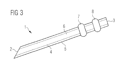
FIG. 3 shows a schematic cross-section of another embodiment of the needle,
wherein the first and the second salient have a circumferential form.
FIG. 4 shows a schematic cross-section of an embodiment of the drug delivery
device.
FIG. 5a/b show a schematic cross-section of a part of an embodiment of the
drug
delivery device as a section wherein the plunger and the seal are in
different positions.
FIG. 6a/b show a schematic cross-section of a part of an embodiment of the
drug
delivery device wherein the plunger and the seal are in different positions
with an additional salient.
FIG. 7a/b show a schematic cross-section of a part of an embodiment of the
drug
delivery device as a section wherein the plunger and the seal are in
different positions.
FIG. 8a-g show a schematic cross-section of an embodiment of the drug delivery
device in seven different steps of use.
FIG. 1 a schematically shows the cross-section of one embodiment of the needle
1.
The needle 1 comprises a distal end 2, a proximal end 3, an inner surface 4
forming a
channel 6, and an outer surface 5. Two first salients 7 are located on the
outer surface
5 in opposite positions with respect to the needle 1. The two first salients 7
have a
hemispherical form in this embodiment.
FIG. 1 b shows a schematic cross-section of another embodiment of the needle
1,
which is similar to the embodiment which is shown in FIG. 1 a. In this
embodiment,
CA 02753939 2011-08-29
WO 2010/100241 PCT/EP2010/052786
13
which is shown in FIG. 1 b, the two first salients 7 have a pyramidal form.
Also these
two salients are located at the outer surface 5 in opposite positions.
FIG. 2 shows a schematic cross-section of another embodiment of the needle 1.
Compared to the needle which is shown in FIG. 1a, the needle in FIG. 2
additionally
has two second salients 8. The second salients 8 are located between the first
salients
7 and the proximal end 3 of the needle. In this embodiment, the second
salients 8 have
the same geometric form, which is hemispherical, as the first salients 7. The
two
second salients 8 are located as the two first salients 7 on opposite sides of
the needle
1. In a further embodiment (not shown) the first salients 7 and second
salients 8 have
a different geometric form.
FIG. 3 shows a schematic cross-section of another embodiment of needle 1.
Compared to the needle which is shown in FIG. 2, the needle which is shown in
FIG. 3
has one first salient 7 and one second salient 8. Both of the salients 7,8
have a
circumferential form with respect to the needle 1. Circumferential means that
both of
the salients have a form that they build a ring around the outer surface 5 of
the needle
1. In a further embodiment (not shown) the first salients 7 and second
salients 8 have
a different geometric form, for example second salients 8 may be larger or
smaller than
first salients 7.
FIG. 4 shows a schematic cross-section of an embodiment of the drug delivery
device
100 with its basic elements. This drug delivery device 100 comprises a body
unit 9, a
needle 1 at the distal end and a plunger 12 at the proximal end. The needle 1
comprises a first and second salient 7,8, which are located inside the body
unit 9. A
seal 15 is located around the needle 1 and between the first and the second
salient
7,8. Inside the body unit 9 there is a void 16 located between the first
salient 7 and the
second opening 11 of the body unit 9. The void 16 is able to at least partly
house the
seal 15. The plunger 9 comprises an outer end 13, which is located outside the
body
unit 9 and an inner end 14, which is located inside the body unit 9. The
plunger 12 can
be pushed to the distal direction through the first opening 10 with respect to
the body
CA 02753939 2011-08-29
WO 2010/100241 PCT/EP2010/052786
14
unit 9. Fig. 4 only shows schematically how the basic parts of the drug
delivery device
100 are arranged relative to each other.
The FIGs. 5a/b each show a schematic cross-section of an section of the drug
delivery
device 100. In both figures, there is a section of the needle 1 on the left
side of the
figure and a section of the plunger 12 on the right side of the figure.
In FIG. 5a, the seal 15 is located between the first and the second salient
7,8 and the
inner end 14 of the plunger 12 is located on the proximal side of the second
salient 8.
On the distal side of the first salient 7, there is a void 16 inside the body
unit 9. A third
salient 22 is located at the second opening 11 of the drug delivery device.
This third
salient prevents the needle 1 from moving to the distal direction, when it is
pushed
from the plunger 9 to this direction. There is a void 16 inside the body unit
9 between
the first salients 7 and the third salient 22.
The FIG. 5b shows the section of the drug delivery device 100 of the FIG. 5a
wherein
the plunger 12 with its inner end 14 has been pushed in a distal direction,
whereby the
seal 15 has been pushed over the first salient 7 into the former void 16. By
moving the
plunger 12 into the distal direction additionally the inner end 14 of the
plunger 12
comes into connection with the needle 1 over the second salient 8 without the
needle 1
moving with respect to the body unit 9, because the third salient 22 prevents
the
needle 1 from moving to the distal direction. The needle 1 may be now not
fixed as
strongly as before by the seal 15 in its position with respect to the body
unit 2. The
decrease in connection strength between needle 1 and seal 15 may be caused by
a
number of means, including, but not limited to, breaking of an adhesive or
static
frictional bond beween the needle 1 and seal 15, the formation of a channel
through
the central region of seal 15 caused by the travel of the seal 15 over first
salient 7
through which the third salient 22 can easily pass, or a difference in size or
geometric
shape between the first and third salient 7,22, for example third salient 22
is smaller or
has an smaller profile compared to first salient 7. Through the connection
between the
plunger 12 and needle 1 over the inner end 14 of the plunger and the second
salient 8
CA 02753939 2011-08-29
WO 2010/100241 PCT/EP2010/052786
of the needle 1, the needle now can be drawn back into the body unit 2 by
means of
drawing back the plunger 9 into proximal direction.
The FIGs. 6a/b show a similar embodiment to that which is shown in the FIGs.
5a/b.
5 The embodiment shown in FIGs. 6a/b additionally has a salient 17 located at
the inner
side of the body unit 9. The salient 17 located at the inner side of the body
unit is
running circumferentially around the whole inner side of the body unit 9. The
salient 17
is located between the first and the second salient 7,8 at the initial
position of the seal
15 as shown in FIG 6a. The salient at the inner side of the body unit 9
additionally fixes
10 the seal 15 in its positionThe third salient 22, which is located at the
second opening
11, has the form of a disc in this embodiment, which runs circumferentially
with respect
to the needle 1. The third salient 22 prevents the needle 1 from moving into
the distal
direction with respect to the body unit 2, when a pressure impacts onto the
needle 1 or
the seal 15 from the proximal direction. Through the pressure from outside of
the seal
15 15, the needle 1 is fixed more strongly, in both proximal and distal
directions, in this
position, for example by salient 17 providing increased compression of the
seal 15
which in turn creates additional mechanical resistance to axial displacement
of the seal
15 and therefore needle 1.
When the seal 15 is pushed into the former void 16 as shown in FIG. 6b, the
compressive force on the seal 15 is reduced because the salient 17 no longer
provides
additional compression to the seal 15. Therefore the needle 1 which runs
through the
seal 15 is not fixed as strongly as before when the seal 15 was located
between the
two salients 7,8. The salient 17 of the inner side of the body unit 9 is
fixedly connected
with the body unit 9 and does not move with the seal 15 into the former void
16. When
the plunger 12 is moved into the distal direction and pushes the seal 15 into
the former
void 16, now the inner end of the plunger 14 moves to the former position of
the seal
15. Therefore, the distal end of the inner end 14 of the plunger 9 is now in
the position
the seal 15 has been before. The parts of the inner end 14 of the plunger
which have
been pushed apart to overcome the second salient 8 are now being pushed
together in
the outgoing position by the salient 17 which is located in the inner side of
the body
unit 9. The compression from the outside onto the inner end 14 of the plunger
CA 02753939 2011-08-29
WO 2010/100241 PCT/EP2010/052786
16
strengthens the connection between the needle 1 and the plunger 12. Therefore,
the
needle 1 is now fixedly connected to the plunger 12 and could be drawn back by
means of moving the plunger 12 into the proximal direction with respect to the
body
unit 9 such that the whole needle 1 is in the end located inside the body unit
9.
The FIGs. 7a/b show a similar embodiment to that which is shown in the FIGs.
6a/b.
The embodiment shown in FIGS. 7a/b has an additional boss 23, through which
needle 1 passes, and does not have a third salient on the needle.
The embodiment shown in FIGs. 7a/b has a salient 17 located at the inner side
of the
body unit 9. The salient 17 located at the inner side of the body unit runs
circumferentially around the whole inner side of the body unit 9. The salient
17 is
located between the first and the second salient 7,8 at the initial position
of the seal 15
as shown in FIG 7a. The salient 17 at the inner side of the body unit 9
additionally fixes
the seal 15 in its positionthus thus that the seal 15 is arrangedin a way,
that its groove
29 is located at the salient 17, for example by providing increased
compression of the
seal 15 which in turn creates additional mechanical resistance to axial
displacement of
the seal 15. The boss 23, which is located at the second opening 11, is in
contact with
the first salient 7. The hole in the boss 23, through which the needle passes,
is a
smaller diameter than the diameter of the first salient 7. Therefore needle 1
is
prevented from moving in the distal direction with respect to the body unit 2,
when a
pressure impacts onto the needle 1 or the seal 15 from the proximal direction.
In thios
position friction between the needle 1 and the seal 15 and the interaction of
the first
salient 7 and seal 15 prevents the needle 1 from moving in the proximal
direction. In
this position salient 17 provides increased compression of the seal 15 which
in turn
creates additional mechanical resistance to axial displacement of the seal 15
and
therefore needle 1.
When the seal 15 is pushed into the former void 16 as shown in FIG. 7b, the
compressive force on the seal 15 is reduced because the salient 17 no longer
provides
additional compression to the seal 15. Seal 15 is pushed over the first
salient 7 and
onto the body protrusion 23. In this position the needle 1 is no longer in
contact with
CA 02753939 2011-08-29
WO 2010/100241 PCT/EP2010/052786
17
seal 15. The salient 17 of the inner side of the body unit 9 is fixedly
connected with the
body unit 9 and does not move with the seal 15 into the former void 16. When
the
plunger 12 is moved into the distal direction and pushes the seal 15 into the
former
void 16, the inner end of the plunger 14 occupies the former position of the
seal 15.
The distal end of the inner end 14 of the plunger 9 is now pushed into
position over
first and second salients 7,8. Therefore, the needle 1 is now fixedly
connected to the
plunger 12. The hole in boss 23 through which needle 1 passes is larger than
the
needle outer diameter and therefore provide no resistance to proximal movement
of
the needle 1. The needle 1 could be drawn back by means of moving the plunger
12
into the proximal direction with respect to the body unit 9 such that the
whole needle 1
is in the end located inside the body unit 9.
The Figures 8a to 8g show a schematic cross-section of an embodiment of a drug
delivery device 100 in seven different steps of use.
FIG. 8a shows an embodiment of the drug delivery device 100 in a schematic
cross-
section. The drug delivery device 100 comprises a needle 1 with a first
salient 7 and a
second salient 8. The needle 1 is located with respect to the body unit 9 in a
way that
the first salient 7 and the second salient 8 are located inside the body unit
9. The drug
delivery device 100 further comprises a plunger 12 with an outer end 13 and an
inner
end 14. The proximal part of the plunger 12 is surrounded by a sleeve 19.
Inside the
sleeve 19 round the plunger 12 a spring 20 is arranged. The spring 20 is pre-
compressed into a stressed condition. The body unit 9 comprises a first
opening 10 at
its proximal end and a second opening 11 at its distal end. Between the first
salient 7
and the second salient 8 there is a seal 15 which is formed circumferentially
with
respect to the needle 1 and which is with its outer end and in contact to a
protrusion 21
which is located at the inner side of the body unit 9. The chamber between the
inner
end 14 of the plunger 12 and the seal 15 is filled with a liquid 18, which
could be a drug
for example. The seal 15 prevents the liquid 18 from running into the void 16.
FIG. 8a
shows the drug delivery device 100 in its starting position.
CA 02753939 2011-08-29
WO 2010/100241 PCT/EP2010/052786
18
FIG. 8b shows an intermediate step of the use of the drug delivery device 100
which is
shown in FIG. 8a. By pushing on the outer end 13 of the plunger 12 the plunger
12
moves with respect to the body unit 9 to the distal direction. By moving the
plunger 12
in the distal direction the liquid 18 which is inside the body unit 9 is
pressed through
the needle 1 and onto the proximal side of the seal 15. The flange of the seal
15 is
pressed onto the protrusion 21. So the seal is fixed with respect to the body
unit 9 and
therefore the needle 1 is fixed also with respect to the body unit 9 by the
seal 15. The
flange of the seal 15 has a relatively large surface area because it is at the
outside
diameter of the body unit 9. The liquid 18 pressure against the flange and
angled
protrusions 21 creates frictional forces between flange and protrusions 21
preventing
the seal 15 being pushed in the distal direction. Furthermore, the needle 1
cannot
move into the distal direction with respect to the body unit 9 because of the
first salient
7 which is located inside the second opening 11 of the body unit 9.
FIG. 8c shows a further intermediate step of the use of the drug delivery
device 100
which is shown in FIG. 8a. Through moving the inner end 14 of the plunger into
the
distal direction, now the inner end 14 has a direct contact to the seal 15.
The distal end
of the inner end 14 of the plunger can now apply a force directly to the
proximal end of
the seal 15.
FIG. 8d shows a further intermediate step of the use of the drug delivery
device 100
which is shown in FIG. 8a. By further pushing the plunger 12 into the distal
direction
with respect to the body unit 9 the inner end 14 which was in direct contact
before with
the seal 15 now pushes the seal 15 in the distal direction with respect to the
needle 1
in a way that the seal 15 loses the direct contact to the protrusion 21. The
flange of the
seal 15 is pulled away from protrusions 21. During this the needle 1 stays in
its position
with respect to the body unit 9. The seal 15 still prevents the fluid 18 from
running into
the void 16.
FIG. 8e shows another intermediate step of the use of the drug delivery device
100
which is shown in FIG. 8a. After the seal 15 has lost the contact to the
protrusion 21 it
can be pushed in the distal direction into the void 16 by pushing the plunger
12 with its
CA 02753939 2011-08-29
WO 2010/100241 PCT/EP2010/052786
19
inner end 14 into the distal direction. The snap arms 24 of the sleeve 19 are
forced
inwards by contact with the body unit 9. In turn the sleeve snap arms 24 cause
the
plunger rod latch arms 25 to deform inwards. The plunger rod latch arms 25
snap
inwards over sleeve latch features 26. The spring 20 now exerts a force in the
proximal
direction on the plunger 12. Proximal movement of the plunger 12 is resisted
by
pressure applied manually to the proximal end surface of plunger 12.
FIG. 8f shows another intermediate step of the use of the drug delivery device
100
which is shown in FIG. 8a. In this step now the seal 15 is located in the void
16.
Therefore the seal 15 no longer offers a resistance to the needle 1 to be
retracted. The
inner end 14 of plunger 12 has now snapped over the second salient 8. Hereby
the
needle 1 is now connected to the plunger 12 over the second salient 8. The
seal 15
still prevents the fluid 18 from running into the void 16 by sealing the areas
in which the
rest of the fluid 18 is located against the void 16. Only a very small and
controlled
amount of the liquid 18 stays in the drug delivery device 100. The sleeve snap
arms 24
lock into recesses 27 of the body unit 9. Therefore the sleeve 19 is now
connected to
the body unit 9 and can no longer move with respect to the body unit 9. The
plunger
rod latch arms 25 of the plunger 9 remain in their deformed condition clear of
the
sleeve latch features 26.
FIG. 8g shows another intermediate step of the use of the drug delivery device
100
which is shown in FIG. 8a. After connecting the plunger 12 over its inner end
14 with
the needle 1 and after separating the seal 15 from the needle 1, the needle 1
can now
be drawn back with respect to the body unit 9 in the proximal direction by the
spring
20, which was pre-stressed. The needle 1 can be drawn back so far that the
whole
needle 1 is located inside the body unit 9. In the end position the inner end
14 contacts
the sleeve 19. The plunger rod snap arms 28 deflect inwards as they pass
through a
hole in the distal end surface of sleeve 19. Once the plunger rod snap arms 28
are
clear of the hole in sleeve 19 the plunger rod snap arms 28 flex outwards to
lock the
plunger 12 in the rearward position relative to the sleeve 19 and prevents the
needle 1
from moving in the distal direction.
CA 02753939 2011-08-29
WO 2010/100241 PCT/EP2010/052786
Reference numerals
1) needle
2) distal end
3) proximal end
4) inner surface
5) outer surface
6) channel
7) first salient
8) second salient
9) body unit
10) first opening
11) second opening
12) plunger
13) outer end
14) inner end
15) seal
16) void
17) salient at the inner side of the body unit
18) liquid
19) sleeve
20) spring
21) protrusion
22) third salient
23) boss
24) snap arms
25) plunger rod latch arms
26) sleeve latch features
27) recesses
28) plunger rod snap arms
29) groove
100) drug delivery device