Note: Descriptions are shown in the official language in which they were submitted.
CA 02753990 2015-05-12
WO 2009/111454 PCT/US2009/035847
XRF SYSTEM HAVING MULTIPLE EXCITATION
ENERGY BANDS IN HIGHLY ALIGNED PACKAGE
[0001] (Blank)
Technical Field
[0002] The present invention relates generally to x-ray analysis systems, and
more
particularly, to x-ray source assemblies providing multiple excitation
energies to
improve detection and analysis of multiple elements in homogeneous and
heterogeneous sample structures.
Background of the Invention
[0003] There is an emerging need to provide manufactured products of all types
in
which the levels of toxins is minimized or completely eliminated. This need
has a
clear underlying medical basis and is accelerated by fear and pending
legislation ¨ the
results of many recent well-publicized cases of toxins in manufactured
products (e.g.,
lead in toys). The costs of unsafe products go well beyond the health impact
to
include significant loss of business, permanent damage to brands and corporate
image, and increased levels of corporate and personal liability.
[0004] In response to these problems, there is a growing trend of increasingly
strict
environmental and health regulations of consumer products around the world.
The list
of products regulated is rapidly increasing and the types and permitted levels
of toxins
are becoming more restrictive. Some industry players arc going beyond thc
regulations for the products they distribute, by mandating even cleaner
products in
their supply chain. Regulations are effectively aimed at decreasing direct
human
-1-
CA 02753990 2011-08-30
WO 2009/111454
PCT/US2009/035847
exposure to toxins by reducing toxins in our environment. Several stricter
standards
can be traced to European environmental directives that began in the early
1990s,
starting with regulations in packaging materials and batteries. In subsequent
years,
reductions on hazardous substances were introduced by the EU for automobiles
(ELV) and two directives related to electronics (Restriction of Hazardous
Substances
or RoHS and Waste Electrical and Electronic Equipment or WEEE). Pending U.S.
Federal legislation lowers allowable lead levels in paint on toys by a factor
of six and
threatens criminal prosecution for companies that violate with penalties
ranging from
$10 million to $100 million for a single violation. In addition, nine other
known
toxins are targeted for restriction, including: mercury, arsenic, cadmium,
barium, and
chromium.
[0005] The spread of such human health and environmental initiatives are
having
profound global implications on the way products are designed, manufactured,
and
ultimately discarded or recycled.
[0006] Current measurement methods for toxins in manufactured products do not
meet the needs of the supply chain, from the factories to the ultimate
consumers.
Identification and measurement of toxins are needed at each step of the chain,
from
raw materials, to components, to finished goods. While raw-material
measurements
are most efficient for factories, distribution channels typically require
measurements
on the final product. New techniques are urgently needed to accurately,
quickly,
consistently, and cost-effectively measure toxins at each stage, with minimal
interruptions in the flow of manufacturing and distribution of the goods.
Because toys
and other manufactured products often have small painted features (pigments
are
often the source of the toxins), it is necessary to measure small areas while
differentiating the paint from the base material.
[0007] Existing low-cost methods of toxin detection are generally ineffective,
e.g.,
swab tests. Higher-cost methods that provide the requisite accuracy are
expensive
and time consuming. These sometimes involve: manually scraping samples,
digesting
them in acids at elevated temperature and pressure, introducing them into a
combustion chamber, and analyzing the combustion product. One widely used
method today is inductively coupled plasma optical emission spectroscopy (ICP-
OES)
-2-
CA 02753990 2011-08-30
WO 2009/111454
PCT/US2009/035847
¨ a method which is expensive, destructive, and slow. Alternatively, handheld
x-ray
fluorescence (XRF) guns are rapid and nondestructive, but are only reliable
for higher
than regulated concentrations, and are averaged across large sample areas, and
cannot
separately evaluate paint layers.
[0008] As discussed further below, the present invention provides a
measurement
solution having fast, accurate results for toxins in manufactured products,
enabled by
sophisticated proprietary x-ray optics. Such proprietary optics typically
provide 10 ¨
1,000x improvements in the ability to focus x-rays; and optic-enabled
analyzers are
especially suited for these targeted markets - moving measurements from the
lab into
the factory, field, and clinic.
[0009] In x-ray analysis systems, high x-ray beam intensity and small beam
spot sizes
are important to reduce sample exposure times, increase spatial resolution,
and
consequently, improve the signal-to-background ratio and overall quality of x-
ray
analysis measurements. In the past, expensive and powerful x-ray sources, such
as
rotating anode x-ray tubes or synchrotrons, were the only options available to
produce
high-intensity x-ray beams, in the laboratory. Recently, the development of x-
ray
optic devices has made it possible to collect the diverging radiation from an
x-ray
source by focusing the x-rays. A combination of x-ray focusing optics and
small,
low-power x-ray sources can produce x-ray beams with intensities comparable to
those achieved with more expensive devices. As a result, systems based on a
combination of small, inexpensive x-ray sources, excitation optics, and
collection
optics have greatly expanded the availability and capabilities of x-ray
analysis
equipment in, for example, small laboratories and in the field, factory, or
clinic, etc.
[0010] Monochromatization of x-ray beams in the excitation and/or detection
paths is
also useful to excite and/or detect very precise portions of the x-ray energy
spectrum
corresponding to various elements of interest (lead, etc.). X-ray
monochromatization
technology is based on diffraction of x-rays on optical crystals, for example,
germanium (Ge) or silicon (Si) crystals. Curved crystals can provide
deflection of
diverging radiation from an x-ray source onto a target, as well as providing
monochromatization of photons reaching the target. Two common types of curved
crystals are known as singly-curved crystals and doubly-curved crystals
(DCCs).
-3-
CA 02753990 2016-10-18
WO 20()9/111454
PCT/IJS2009/035847.
Using what is known in the art as Rowland circle geometry, singly-curved
crystals
provide focusing in two dimensions, leaving x-ray radiation unfocused in the
third or
orthogonal plane. Doubly-curved ciystals provide focusing of x-rays from the
source
to a point target in all three dimensions. This three-dimensional focusing is
referred
to in the art as "point-to-point" focusing.
100111 Commonly-assigned -U.S. Patent Nos. 6,285,506 and 7,035,374 disclose
various configurations of curved x-ray optics for x-ray focusing and
monochromatization. In general, these patents disclose a flexible layer of
crystalline
material (e.g., Si) formed into curved optic elements. The monochromating
function,
and the transmission efficiency of the optic are determined by the crystal
structure of
the optic.
[0012] The ability to focus x-ray radiation to smaller spots with higher
intensities,
using focusing and monochromating x-ray optics, has enabled reductions in the
size
and cost of x-ray tubes, and x-ray systems have therefore been proliferating
beyond
the laboratory to in-situ, field uses. Commonly-assigned U.S. Patents Nos.
6,934,359
and 7,072,439 disclose
monochromatic wavelength dispersive x-ray fluorescence (MWD XRF) techniques
and systems, using doubly curved crystal optics in the excitation and/or
detection
paths. The x-ray optic-enabled systems described in these patents have enjoyed
widespread success beyond the laboratory, for measuring sulfur in petroleum
fuels in
a variety of refinery, terminal, and pipeline environments.
100131 In such systems, precise optic alignment along an axis defined by a
source and
sample spot may be required, as illustrated in U.S. Patent No.
7,035,374, which proposes an arrangement of curved, monochromating optics
around
a central axis operating according to Bragg diffraction conditions. Fig. la is
a
representative isometric view of this x-ray optic arrangement 150 having a
curved
optic 152, an x-ray source location 154, and an x-ray target location 156. X-
ray
source location 154 and x-ray target location 156 define a source-to-target
transmission axis 162. Optic 152 may include a plurality of individual optic
crystals
164, all of which may be arranged symmetrically about axis 162.
-4-
CA 02753990 2015-05-12
WO 2009/111454 PCT/US2009/035847
[0014] Fig. lb is a cross-sectional view taken along section lines lb-- lb of
Fig. la,
wherein the surface of optic 152, x-ray source location 154, and x-ray target
location
156 define one or more Rowland (or focal) circles 160 and 161 of radius R for
optic
152. Those skilled in the art will recognize that the number and orientation
of the
Rowland circles associated with crystal optic 152, or individual crystals 164,
will vary
with the position of the surface of optic crystal 152, for example, the
variation of the
toroidal position on optic crystal 152.
[0015] The internal atomic diffraction planes of optic crystal 152 also may
not be
parallel to its surface. For example, as shown in FIG. lb, the atomic
diffraction
planes of crystal 152 make an angle yi with the surface upon which x-rays are
directed, at the point of tangency 158 of the surface and its corresponding
optic circle
160 or 161. OB is the Bragg angle for crystal optic 152 which determines its
diffractive effect. Each individual optic crystal can in one example be
fabricated
according to the method disclosed in above- noted U.S. Pat. No. 6,285,506,
entitled "Curved Optical Device and Method of Fabrication."
10016] All individual crystals 164 should be aligned to the source-to-target
axis 162,
for proper Bragg conditions. Improvement in optic alignment, especially for
such
multiple-crystal optics, therefore remains an important area of interest.
Another issue,
which particularly affects volume manufacturing, is the need to align
disparate
components which may be purchased from different vendors. For example, the x-
ray
tubes, when purchased in quantities from a vendor, may have source x-ray spots
which are not consistently centered relative to their own housings. Re-
centering these
x-ray tube spots is necessary, as an initial step in the alignment process for
an entire
x-ray source assembly.
[00171 Various optic/source combinations have already been proposed to handle
thermal stability, beam stability, and alignment issues, such as those
disclosed in
commonly assigned U.S. Patents Nos. 7,110,506; 7,209,545; and 7,257,193.
In particular,
Patents Nos. 7,209,545 (entitled "X-Ray Source Assembly Having Enhanced Output
Stability, and Fluid Stream Analysis Applications Thereof') and 7,257,193
(entitled
"X-Ray Source Assembly Having Enhanced Output Stability Using Tube Power
-5-
CA 02753990 2011-08-30
WO 2009/111454
PCT/US2009/035847
Adjustments and Remote Calibration") address certain tube/optic alignment
problems
during source operation with real-time, corrective feedback approaches for
alignment
between the tube focal spot, optic, and output focal spot. Sensors are used to
detect
various operating conditions, and mechanical and/or thermal adjustments are
made to
correct for instabilities, including misalignments. These types of systems are
necessary and valuable for certain applications, but can also increase the
cost and
complexity of fielded systems.
[0018] The above-described XRF technology and systems have been useful in
single
element analyzers for measuring generally homogeneous sample structure (e.g.,
sulfur
in petroleum products). However, the measurement of toxins in manufactured
products presents an additional level of challenges. First, an instrument
should have
the capability to measure more than one element simultaneously or near-
simultansously, from a relatively confined list of about 10 toxic elements,
discussed
above. Moreover, manufactured products are likely to be heterogeneous in
nature,
requiring small spot resolution, as well as the ability to detect toxins in
one of a
number of heterogeneous layers (e.g., the level of lead in a paint layer and a
substrate
layer beneath the paint).
[0019] Improved x-ray analysis method and systems are required, therefore, to
address the problems associated with measuring multiple toxins in potentially
heterogeneous samples, to enable in-the-factory and/or in-the-field
measurement of
toxins in manufactured products.
Summary of the Invention
[0020] The shortcomings of the prior art are overcome and additional
advantages are
provided by the present invention, which in one aspect is an x-ray analysis
apparatus
for illuminating a sample spot with an x-ray beam. An x-ray tube is provided
having
a source spot from which a diverging x-ray beam is produced having a
characteristic
first energy, and bremsstrahlung energy. A first x-ray optic receives the
diverging x-
ray beam and directs the beam toward the sample spot, while monochromating the
beam; and a second x-ray optic receives the diverging x-ray beam and directs
the
beam toward the sample spot, while monochromating the beam to a second energy.
-6-
CA 02753990 2011-08-30
WO 2009/111454
PCT/US2009/035847
The first x-ray optic may monochromate characteristic energy from the source
spot,
and the second x-ray optic may monochromate bremsstrahlung energy from the
source spot. The x-ray optics may be curved diffracting optics, for receiving
the
diverging x-ray beam from the x-ray tube and focusing the beam at the sample
spot.
Detection is also provided to detect and measure various toxins in, e.g.,
manufactured
products including toys and electronics.
[0021] The present inventors have developed these novel and effective
techniques to
address the growing market need to scrutinize toxins in manufactured goods.
Optic-
enabled, monochromatic-excited, micro-focus energy-dispersive XRF utilizes the
above-discussed advanced x-ray optics together with a low-wattage x-ray tube,
commercially available sensors, and proprietary software algorithms in a
compact
touch-and-shoot design. The optics greatly improve the signal-to-noise and
concentrate the intensity in a small spot. The optic-enabled analyzer can
nondestructively detect and quantify multiple toxic elements simultaneously in
the
small features typically found in products such as toys and electronics,
regardless of
the product's shape, size, or homogeneity. Its simple-to-use design enables
the
quantifiable measurement of toxin concentrations as low as 1 ppm. The system
maintains secure records including clear time-stamped photographic
identification of
the toy and feature measured, ensuring auditable compliance.
[0022] Doubly Curved Crystal (DCC) monochromating optics can be used to
enhance
measurement intensities by capturing x-rays from a divergent source and
redirecting
them into an intense focused beam on the surface of the product. Their small
spot
size allows the analyzer to inspect small features down to 1.5mm in diameter
with no
reduction in speed or data quality. This unique capability will distinguish
very small
features commonly seen in toys and electronics. Regulations require that each
material be evaluated separately; the limits are per material and color, not
averaging
across multiple features.
[0023] The favorable signal-to-noise ratio enabled by the optics provides the
analyzer
with extremely low limits of detection. This high-performance limit-of-
detection
increases the reliability of results, hence dramatically reducing the number
of false
-7-
CA 02753990 2011-08-30
WO 2009/111454
PCT/US2009/035847
positives or negatives. The analyzer will remain effective even at lowest
proposed
regulatory limits of 4Oppm for lead.
[0024] Paint coatings are of particular interest in the toy market so the toy
analyzer
has incorporated a dedicated coating optic with optimum energy levels and
angles to
isolate paint layers. Conventional XRF technologies without optics take an
average
of the coating and substrate layers that can mask high toxin levels in the
paint layer.
The toy analyzer can distinguish the composition of the paint coating layer
from the
substrate.
[0025] The multi-element capability can simultaneously provide results on the
most
requested toxins in toys and other consumer products. At least 26 different
elements
can be detected simultaneously using the system, with emphasis on the 10
toxins of
greatest interest to manufacturers including Cr, As, Br, Cd, Sb, Ba, Se, Hg,
Cl & Pb.
[0026] Further, additional features and advantages are realized through the
techniques
of the present invention. Other embodiments and aspects of the invention are
described in detail herein and are considered a part of the claimed invention.
Brief Description of the Drawings
[0027] The subject matter which is regarded as the invention is particularly
pointed
out and distinctly claimed in the claims at the conclusion of the
specification. The
foregoing and other objects, features, and advantages of the invention are
apparent
from the following detailed description taken in combination with the
accompanying
drawings in which:
[0028] Figs. la-b depict an exemplary arrangement of crystal x-ray optics
about an axis, requiring alignment;
[0029] Fig. 2 is a perspective view of an aligned x-ray optic and source
assembly, in accordance with one aspect of the present
invention;
[0030] Fig. 3 is a sectional view of the assembly of Fig. 2;
[0031] Fig. 4 is an exploded view of the assembly of Fig. 2;
-8-
CA 02753990 2015-05-12
WO 2009/111454 PCT/US2009/035847
[0032] Figs. 5a-b show the typical characteristic line and bremsstrahlung
radiation from an x-ray tube;
[0033] Figs. 6a-b show the impact of monochromating the x-ray tube
energy and the improved detection results;
[0034] Figs. 7a-b show the various element peaks due to monochromated
excitation energy, and the potential placement of multiple,
monochromatic excitation energy beams, in accordance with
the present invention;
[0035] Fig. 8 is a schematic of the x-ray paths established by three
different focusing, monochromating x-ray optics in accordance
with the present invention; and
[0036] Fig. 9 shows an exemplary excitation of a sample toy with the
proposed apparatus in accordance with the present invention,
for measuring 10 elements of interest.
Best Mode for Carrying Out the Invention
Highly-Aligned X-Ray Source Assembly:
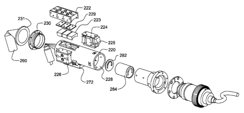
[0037] In accordance with the present invention, Figs 2-4 depict in various
views
(using like numerals to refer to like elements) a highly-aligned x-ray optic
and source
assembly 200 in accordance with the present invention. Various aspects of this
package have been disclosed in the commonly assigned, previously-filed and
published U.S. application serial Nos. 12/920,641, 12/397,504 and 14/052,078.
[0038] As discussed in those Applications, the assembly includes a first
section 210,
second section 220, and third section 230, which together align an x-ray tube
240 to a
sample spot 250, along a central transmission axis Z. Also aligned along this
axis are
multiple optic carriage assemblies 222, 224, and 226 which hold exemplary
-9-
CA 02753990 2011-08-30
WO 2009/111454
PCT/US2009/035847
monochromating optics also requiring alignment to transmission axis Z (as
discussed
above with respect to Figs. la-b).
[0039] First housing section 210 may include adjustable tube-mounting features
212,
214 about its perimeter for adjustably mounting tube 240 thereby ensuring
centering
of tube x-ray spot 242 centrally along a central axis of section 210 (not
shown). As
discussed below, further attachment of assembly sections 210, 220, and 230
will
ensure that each respective section's axis (not shown) is ultimately aligned
to the
transmission axis Z. Therefore, the present invention allows for incremental
alignment of potentially disparate components along the central transmission
axis Z.
For x-ray tube 240, they may be shipped with slightly off-center tube spots
from the
manufacturer, and therefore are required to be re-centered along section 210's
axis
using adjustable mounting features 212 and 214 (e.g., set screws).
[0040] The ability to provide an efficient, economical, portable analysis
capability
depends to a large extent upon x-ray tube and optic technology. In that
regard, certain
tube and optic technology can be combined for smaller, portable systems, e.g.,
a
compact, electron-bombardment x-ray tube. One example of this type of x-ray
tube is
available from Oxford Instruments ¨ model # 5011, which operates at less than
100
watts (i.e., 75 watts) at a cost of less than $1500 per tube, in contrast to
higher-power,
laboratory sources which can cost many thousands, or hundreds of thousands of
dollars ¨ which is cost prohibitive for many applications. Another example is
the
Varian VF-50J (similar to that depicted here), tubular in shape, and which
operates at
50 watts or less, at a cost of several thousand dollars each, with a
molybdenum
material, as discussed further below.
[0041] Second housing section 220 includes additional alignment features.
First,
complimentary mating surfaces 216 and 228 (Fig. 4) are provided to align the
axes of
sections 210 and 220 upon assembly, i.e., upon insertion of tube section 210
into
section 220. Sections 210 and 220 are separately fabricated to guarantee
alignment
along their axes, and therefore to the central axis Z, when the mating
surfaces are in
contact.
-10-
CA 02753990 2015-05-12
WO 2009/111454 PCT/US2009/035847
[0042] Sections 210, 220, and 230 are shown in a form of tubular shape.
Specifically,
the sections are shown in the approximate form of a cylinder, with a circular
cross-
section, which is one type of tubular shape. The cross-section of tubular
sections 210
and 220 could also be square, rectangular, etc. The tubular shapes shown, with
circular cross-sections, provide a section-section alignment technique using
outer
perimeter mating surface 216 of section 210 and inner perimeter mating surface
218
of section 220. The fully enclosed tubular sections also provide required x-
ray
shielding.
100431 Second, section 220 also accommodates the attachment of optic carriages
222,
224, and 226, which are fabricated to adjustably mount and align x-ray optics
223,
225, and 227 (not shown but implied within carriage 226) respectively, to
section 220
and, ultimately, to transmission axis Z. X-ray beam focusing and/or
monochromating
can be accomplished using certain focusing and/or collimating optics, for
example,
curved crystal monochromating optics such as those disclosed in commonly
assigned
U.S. Patents Nos. 6,285,506; 6,317,483; and 7,035,374; and/or multilayer
optics;
and/or polycapillary optics such as those disclosed in commonly assigned U.S.
Patents Nos. 5,192,869; 5,175,755; 5,497,008; 5,745,547; 5,570,408; and
5,604,353.
Of
particular interest are curved monochromating optics (discussed above with
reference
to Figs. la-b), which require precise alignment along, and a certain distance
from, the
transmission axis to meet the appropriate Bragg conditions of interest. Also
of
particular interest is the requirement to align multiple such optics (e.g.,
223, 225, 227)
along a single Z axis.
[0044] The exemplary curved crystal optics 223, 225, and 227 within the second
housing section receive the diverging x-ray beam from x-ray tube spot 242, and
focus
diffracted beam(s) to sample spot 250. The carriages 222, 224, and 226 are
mountable either directly or indirectly to the second housing section, such
that an
active surface of the optic is aligned along, and positioned a desired
distance from, the
transmission axis Z. The outer surface area (e.g., outer diameter) of thc
second
housing section to which the carriage is mounted can be appropriately sized
(e.g., by
outer radius) and fabricated such that the at least one x-ray optic is
positioned the
desired distance from the transmission axis. Moreover, a shim 229, and/or
other
-11-
CA 02753990 2011-08-30
WO 2009/111454
PCT/US2009/035847
spacing adjusters (set screws, etc) can be employed to ensure proper optic
alignment
(Figs. 3-4). Notably, these types of optics, to maintain their Bragg condition
conditions, may be mounted along a surface of the second housing section,
while
separated from the transmission axis Z.
[0045] Third housing section 230 includes an aperture at its point, which
requires
alignment to transmission axis Z for proper illumination of sample spot 250
with the
focused x-ray beam(s) from the optic(s). A cone 231 within this section may
also be
included for additional shielding, rigidly or adjustably mounted to section
230.
Section 230 may also have rigidly mounted thereon an exemplary energy-
dispersive
detector 260 which itself requires close alignment to transmission axis Z. To
effect
alignment of section 230 with sections 220 and 210 (thereby completing
alignment of
the entire source assembly along transmission axis Z), complimentary mating
surfaces
and/or adjustable mounting means (e.g., set screws) can be employed to align
housing
section 230 to section 220 and therefore to section 210. Section 230 and/or
cone 231
can also be adjusted in directions orthogonal to the transmission axis Z.
Other types
of detectors (e.g., wavelength dispersive) may also be used with or without
similar
optics in the detection path. Additional issues should be considered regarding
detector alignment. Energy dispersive detector 260 may also have its own focal
spot
in space, which also requires alignment to beam/sample focal spot 250 (e.g.,
Figs. 2-
3). (Sample spot 250 may be at the surface, or below the surface, of the
sample;
depending on the focal point of the x-ray beam.) As shown, detector is mounted
to
cone 31, which may have adjustable mounting means (shims, set screws, etc.),
as well
as a predetermined mating surface, which ensure alignment of the detector.
Using
this approach, end-to-end alignment of the x-ray tube, optic(s), sample spot,
and
detector is provided.
[0046] Additional shims can be placed between each section (210, 220, 230) to
control their respective spacings and therefore their longitudinal placement
along
transmission axis Z.
[0047] Also shown is an automated shutter system having its own carriage 272,
motor
274 and shutter plates 276. This shutter can be used for x-ray safety purposes
(i.e.,
full blocking shutter), and also for selecting which x-ray beams (from the
optics)
-12-
CA 02753990 2011-08-30
WO 2009/111454
PCT/US2009/035847
should be applied to the sample, in any mix ranging from individual non-
simultaneous
excitation, to full simultaneous excitation, or any mix thereof This is
especially
important for the multiple-energy excitation techniques discussed below.
[0048] Other blocking slits 282 and 284 can also be provided along the beam
path to
tailor the beam striking the optics, and reduce other noise and/or scatter.
[0049] The above approach provides a highly aligned x-ray optic and source
assembly using various techniques to ensure alignment of disparate components
(optics, x-ray tubes, detectors, etc) in a small, rugged, portable, analyzer
for in-situ,
on-line, measurements in industrial process, clinical, and field settings.
Volume
manufacturing is enabled, even when components of varying dimensional
tolerances
are introduced into the production. Moreover, the highly aligned assembly
provides
the precision alignment required by focusing, diffractive optics according to
Bragg
conditions. Any mis-alignment of the optics will directly impact the precision
of the
device.
Monochromating Optics At Different Energies:
[0050] The benefit of using a monochromatic excitation beam for XRF in such a
package can be better understood with reference to the output spectrum of a
typical x-
ray molybdenum target tube shown in Fig. 5a - showing characteristic lines
from the
tube's target material at about 17keV, and a broader bremsstrahlung radiation
spectrum. When this x-ray beam impinges on a sample, the secondary x-rays
emitted
from the sample have two components: the fluorescent characteristic lines of
the
elements in the sample and scattered x-rays from the source as shown in Fig.
5b. An
energy dispersive (ED) detector measures the sum of the two. Therefore, the
fluorescence signals of trace elements in the sample can be obscured by the
background. Using a point-focusing, monochromatic optic between the source and
the sample, the optic only diffracts the tube's characteristic line from the
source.
Therefore the spectrum of the beam that impinges on the sample is much
simpler, as
shown in Fig. 6a. The spectrum that emerges from the sample now has a much
lower
background at all energies except at the Compton scattering region. Fig. 6b
illustrates
-13-
CA 02753990 2011-08-30
WO 2009/111454
PCT/US2009/035847
the scattering spectrum with the fluorescence signal from a sample. The trace
element
signals undetected in Fig. 5b are now clearly detectable.
[0051] In accordance with another aspect of the present invention, multiple
optics 223
and 225 (and others) of apparatus 200 may be different, i.e., may be tuned to
different
parts of the x-ray energy spectrum, to optimize element detection and
quantification
in respective areas of the x-ray energy band. In general, for an element to
fluoresce
and therefore be subject to detection and measurement, the excitation energy
must be
at or above the element's x-ray absorption edge. Causing all of the elements
of
interest to fluoresce therefore requires an excitation energy above the
absorption
edges of all of the elements of interest.
[0052] With reference to the comparative graph of Fig. 7a, this graph shows
initially
that an optic producing monochromatic excitation improves elemental detection
by
orders of magnitude (trace 710) versus the conventional polychromatic
excitation
(trace 720).
[0053] As discussed above, and with further reference to Fig. 7b, a
characteristic
energy line El from, e.g., a molybdenum target x-ray tube at approximately
17keV, is
focused to the sample using a point-focusing, monochromating optic as
discussed
above, generally causing all elements having fluorescent lines of interest
lower that
17keV to fluoresce (e.g., trace 710). Its excitation effect gradually
diminishes,
however, for elements having fluorescence lines much lower (e.g., less than
10keV in
this example).
[0054] In accordance with the present invention, additional optic(s) can be
employed
to simultaneously capture the non-characteristic, broad bremsstrallung energy
transmitted from the same x-ray tube, and provide additional lines of
excitation
energy, at e.g., energies E2, E3, E4, E5 ... each line from a respective point-
focusing,
monochromating optic. Energies higher than 17keV (not shown) can also be used.
This technique can be used for efficient, low-background excitation of various
ranges
of elements in the periodic table.
[0055] In the particular system embodiment 200 shown herein and with further
reference to the x-ray path diagram of Fig. 8, three optics 223, 225, and 227
provide
-14-
CA 02753990 2011-08-30
WO 2009/111454
PCT/US2009/035847
the 31 keV (from bremsstrallung), the 17keV characteristic molybdenum line,
along
with the 7keV line (also from bremsstrahlung), respectively.
[0056] These lines provide optimized excitation of the following approximate
ranges
of elements of interest from the periodic table (listed along with their
atomic
numbers):
[0057] 3 lkeV: From about Zr (40) to Te (52)
[0058] 17keV: From about Cl (17) to Br (35); Rb(37) to Sr(38); Zr(40);
[0059] Cs(55) to Bi(83); Th(90); U(92)
[0060] 7keV: From about Al (13) to Co (27)
[0061] By using different optics, different excitation angles and/or energies
can be
simultaneously (or sequentially, or any mix thereof using a shutter system)
applied to
the sample. Because different energies cause different fluorescence effects,
more
information can be determined in the detection path. For example, higher
energies
penetrate deeper depths and can be used to detect substrate (rather than
painted) layers
in the material. Moreover, even though lower energies may penetrate the paint
levels,
the resultant fluorescence may not, giving more insight into material makeup.
[0062] Certain elements exist in the energy band at spacings that generally
exceed a
detector's ability to resolve (e.g., Cd and Sn), and in fact have overlapping
K/L lines
and absorption energies. And tin (Sn), a commonly used lead substitute, may
mask
the cadmium in the detection path. Therefore, excitation just below the
absorption of
the higher element (Sn), thereby not exciting the tin but effectively exciting
all the
cadmium, can be used to isolate the lower element (Cd).
[0063] Ratios of fluorescence spectra caused by two different excitation
energies can
also be exploited for additional information about the sample.
[0064] Fig. 9 shows an exemplary excitation of a sample toy with the proposed
apparatus in accordance with the present invention, for measuring 10 elements
of
interest.
-15-
CA 02753990 2015-05-12
WO 2009/111454 PCT/US2009/035847
100651 Multi-element optics (e.g., 223) can be used in accordance with the
above-
noted U.S. Patent 7,035,374. Moreover, layered optics can be used, in
accordance with multilayer techniques, and/or multi-crystal-layer techniques
as
disclosed in U.S. Patent Application No. 11/941,377 filed on November 16, 2007
entitled X-RAY FOCUSING OPTIC HAVING MULTIPLE LAYERS WITH
RESPECTIVE CRYSTAL ORIENTATIONS.
Such DCCs are referred to herein as LDCCs. There are several unique
features of LDCC optics. The rocking curve width of the optic can be designed
to be
2 to 5 times higher than single layer DCC optics. This will increase the
bandwidth
and provide flux increase for slicing the bremsstrahlung spectrum. For a
single layer
Si or Ge DCC, the rocking curve can be narrow such that its efficiency is
reduced by
the finite size of a typical x-ray point source. The LDCC can be designed to
match
the source size and improve the transmitted flux for focusing characteristic
lines as
well. The LDCC optics may also work better for higher energy photons. A more
layered structure can be built for high energy x-rays due to reduced
absorption. The
useful energy range for the LDCC is expe,cted to be 6 - 50 keV.
[00661 In one particular example, three LDCC optics can be used to provide a
tri-
chromatic focused beam from a small spot Cu target source. The first LDCC
focuses
Cu Kal 8.04keV characteristic x-rays to the sample spot. The spot size is
approximately 50nm to 75nm. The Cu LDCC covers the excitation for elements
from
Silicon (Si) to Manganese (Mn) including Cr. The second LDCC selects and
focuses
a band of bremsstrahlung centered at 16 keV for Hg, Pb and Br excitation. The
third
LDCC selects and focuses a band of bremsstrahlung centered at 28 keV for Cd
excitation. The two bremsstrahlung optics have focused spots of 100um to 300
m.
The bandwidth of the bremsstrahlung optics are designed to be about 1-2 A) of
the
focusing energy. A PIN diode detector is used for EDXRF spectrometry. A
shutter
scheme can be constructed between the x-ray source and the optics, or between
the
optics and the sample (as discussed above) to have the option to turn the beam
from
each optic on and off, in any combination. A camera and/or laser spot can be
placed
in the center of the three optics in order to visually locate the measurement
spot. The
camera will also be used to store the image along with the spectral data. A
small
laser-height gauge is used to aid in the positioning of the sample at the
focal point.
-16-
CA 02753990 2015-05-12
WO 2009/111454 PCT/US2009/035847
100671 The trend toward increasing global regulation of toxins presents an
opportunity for such highly aligned systems as a platform technology to
address a
number of currently important applications. The disclosed system provides
several
advantages over previous toxin detection technologies with the combined
ability to
non-destructively detect very low levels, isolate small features, and give
reliable
results across a wide range of toxic elements. Conventional XRF analyzers and
more
standard analytical chemistry techniques do not possess the needed combination
of
reliable results, some level of portability, and low cost per test needed in
today's
tightening regulatory environment. Areas that are in need of these attributes
include
consumer products, electronics, air quality monitoring, body fluids, food
products,
and pharmaceuticals. Many of these applications can, in principle, share a
common
hardware and software platform, to hasten new product introductions, lower
manufacturing costs, and provide higher quantities of precision instruments.
100681 The scope of the claims should not be limited by the preferred
embodiments
set forth in the examples, but should be given the broadest interpretation
consistent
with the description as a whole.
-17-