Language selection

Search

Patent 2754452 Summary

Third-party information liability

Some of the information on this Web page has been provided by external sources. The Government of Canada is not responsible for the accuracy, reliability or currency of the information supplied by external sources. Users wishing to rely upon this information should consult directly with the source of the information. Content provided by external sources is not subject to official languages, privacy and accessibility requirements.

Claims and Abstract availability

Any discrepancies in the text and image of the Claims and Abstract are due to differing posting times. Text of the Claims and Abstract are posted:

  • At the time the application is open to public inspection;
  • At the time of issue of the patent (grant).
(12) Patent: (11) CA 2754452
(54) English Title: HYDRAULICALLY RELEASED WINDOW MILL
(54) French Title: FRAISE A FENETRE LIBEREE HYDRAULIQUEMENT
Status: Granted
Bibliographic Data
(51) International Patent Classification (IPC):
  • E21B 29/06 (2006.01)
  • E21B 7/08 (2006.01)
(72) Inventors :
  • STOWE, CALVIN J. (United States of America)
  • MCNICOL, JAMES M. (United States of America)
  • PONDER, ANDREW D. (United States of America)
(73) Owners :
  • BAKER HUGHES INCORPORATED (United States of America)
(71) Applicants :
  • BAKER HUGHES INCORPORATED (United States of America)
(74) Agent: MARKS & CLERK
(74) Associate agent:
(45) Issued: 2013-11-26
(86) PCT Filing Date: 2010-03-03
(87) Open to Public Inspection: 2010-09-10
Examination requested: 2011-09-02
Availability of licence: N/A
(25) Language of filing: English

Patent Cooperation Treaty (PCT): Yes
(86) PCT Filing Number: PCT/US2010/026067
(87) International Publication Number: WO2010/102015
(85) National Entry: 2011-09-02

(30) Application Priority Data:
Application No. Country/Territory Date
12/396,986 United States of America 2009-03-03

Abstracts

English Abstract


An affixation and release arrangement includes a first
component having a fluid pressure chamber; a piston mounted in the
first component and exposed to the fluid pressure chamber; a second
component affixed to the first component through the piston, the pis-ton
responsive to fluid pressure increase within the chamber to unaf-fix
the second component from the first component. Methods are in-cluded.


French Abstract

La présente invention concerne un agencement de fixation et de libération, comprenant : un premier composant comportant une chambre de pression hydraulique ; un piston monté dans le premier composant, et exposé à la chambre de pression hydraulique ; un second composant fixé au premier composant via le piston, le piston répondant à l'augmentation de pression hydraulique dans la chambre pour séparer le second composant du premier composant. L'invention concerne également des procédés correspondants.

Claims

Note: Claims are shown in the official language in which they were submitted.


What is claimed is:

1. An affixation and release arrangement for a whipstock and a mill in a
borehole comprising:
a mill having a fluid pressure chamber;
a piston mounted in the mill and exposed to the fluid pressure chamber; and
a whipstock affixed to the mill through the piston, the piston responsive to
applied fluid pressure from surface within the chamber to unaffix the
whipstock from
the mill.
2. An affixation and release arrangement as claimed in claim 1, wherein the

whipstock is affixed to the mill by a fastener.
3. An affixation and release arrangement as claimed in claim 2, wherein the

fastener is threaded.
4. An affixation and release arrangement as claimed in claim 2, wherein the

fastener is a press fit fastener.
5. An affixation and release arrangement as claimed in claim 2, wherein the

fastener includes a parting feature.
6. An affixation and release arrangement as claimed in claim 5, wherein the

parting feature facilitates parting under tensile load.
7. An affixation and release arrangement as claimed in claim 5 or 6,
wherein the
parting feature preserves fastener strength in at least one of shear and
bending.
8. An affixation and release arrangement as claimed in claim 1, wherein the

whipstock is affixed to the mill by a securement to the piston.
9. An affixation and release arrangement as claimed in claim 8, wherein the

securement is a ring.

6


10. An affixation and release arrangement as claimed in claim 8, wherein
the
securement is a pin.
11. An affixation and release arrangement as claimed in any one of claims 1
to
10, wherein the piston includes a piston head and a piston tail, the piston
head having
greater area than the piston tail.
12. An affixation and release arrangement as claimed in claim 11, wherein
each
of the piston head and the piston tail includes stops.
13. A method for releasing a mill and whipstock combination comprising:
(a) pressuring a piston within a chamber of the mill;
(b) loading a fastener with the piston;
(c) overcoming the fastener; and
(d) releasing the mill from the whipstock.
14. A method as claimed in claim 13, wherein the pressuring is by applied
pressure from a surface location.
15. A method as claimed in claim 13, wherein the pressuring is local to the
mill
and whipstock.
16. A method as claimed in any one of claims 13 to 15, wherein the loading
of
the fastener is tensile.
17. A method as claimed in claim 13, wherein the overcoming of the fastener
is
parting of the fastener.
18. A method for releasing a mill and whipstock combination comprising:
(a) pressuring a piston within a chamber of the mill;
(b) loading a securement engaged with the piston;
(c) overcoming the securement; and
(d) releasing the mill from the whipstock.

7

Description

Note: Descriptions are shown in the official language in which they were submitted.


CA 02754452 2013-05-24
HYDRAULICALLY RELEASED WINDOW MILL
Inventors: STOWE, Calvin J., MCNICOL, James M., PONDER, Andrew D.
BACKGROUND
[0001] In the hydrocarbon industry it is common to run a whipstock and a mill
in the
same run by hanging the whipstock from the end of the mill string. Generally
this is
done by using a bolt at an uphole end of the whipstock that runs into the mill
to
support the weight of the whipstock during run in. Once the whipstock has
landed at
a selected position and orientation within the borehole, the whipstock is
anchored in
place and will bear weight. The mill is then separated from the whipstock by
set
down weight on the bolt that extends from the whipstock to the mill. The bolt
is
sheared to effect separation. Because the whipstock is necessarily thinner at
the
uphole end thereof, it has commonly been a practice in the industry to use a
lug at the
uphole end of the whipstock to support the shear load with minimal distortion
of the
whipstock. While this arrangement does tend to work as planned, it also
presents a
heavy piece of material that is significantly less than a full circle thereby
guaranteeing
an interrupted cut. Such interrupted cuts are known to damage the mill but
this has
traditionally been endured due to the lack of any alternative arrangement that
will
function more favorably.
SUMMARY
[0002] An affixation and release arrangement for a whipstock and a mill in a
borehole comprises: a mill having a fluid pressure chamber; a piston mounted
in the
mill and exposed to the fluid pressure chamber; and a whipstock affixed to the
mill
through the piston, the piston responsive to applied fluid pressure from
surface within
the chamber to unaffix the whipstock from the mill.
[0003] A method for releasing a mill and whipstock combination comprises
pressuring a piston within a chamber of the mill; loading a fastener with the
piston;
overcoming the fastener; and releasing the mill from the whipstock.
1

CA 02754452 2011-09-02
WO 2010/102015 PCT/US2010/026067
[0004] A method for releasing a mill and whipstock combination including
pressuring
a piston within a chamber of the mill; loading a securement engaged with the
piston;
overcoming the securement; releasing the mill from the whipstock.
BRIEF DESCRIPTION OF THE DRAWINGS
[0005] Referring now to the drawings wherein like elements are numbered alike
in
the several figures:
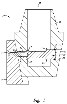
Figure 1 is a schematic view of a mill connected to a whipstock with a piston
actuated affixation arrangement as taught herein;
Figure 2 is a schematic view of the mill and whipstock disconnected by piston
actuation;
Figure 3 is a schematic view of an alternate embodiment.
DETAILED DESCRIPTION
[0006] Referring to Figure 1 an affixation and release arrangement 10 is
illustrated.
The specifically depicted embodiment is an affixation between a first
component such
as a mill 12 and a second component such as a whipstock 14 but it is to be
appreciated
that the concept hereof can be extended to other affixations that require
separation.
Referring directly to the Figures, the mill 12 defines a chamber 16 therein. A
piston
18 is disposed in pressure communication with the chamber 16 such that a
change in
pressure in the chamber will cause a change in position of the piston 18. In
one
embodiment, the arrangement is configured to cause the piston 18 to move upon
a
pressure increase in the chamber 16. In the illustrated embodiment, this is
affected by
configuring the piston 18 with a differential area end to end. Hence upon
increased
pressure, the piston will move. Addressing specifically the differential area
of the
piston 18, it is noted that in the illustration, the portion of the piston 18
that for
convenience is referred to here as piston head 20, on the right side of
drawing Figure
1 is of a dimension that is larger than that of a portion of the piston 18,
referred to
herein for convenience as piston tail 22. Piston head 20 and piston tail 22
are
accommodated laterally in the mill 12 in bores 24 and 26 that are sized to
promote
fluid pressure sealability with the piston head 20 and piston tail 22,
respectively.
Sealing is enhanced by the provision of seals 28 and 30 at each of piston head
20 and
piston tail 22. In one embodiment the seals 28 and 30 are o-rings. In the
condition of
2

CA 02754452 2011-09-02
WO 2010/102015 PCT/US2010/026067
piston 18 as described it will be evident to one of ordinary skill in the art
that
increasing fluid pressure in chamber 16 will cause the piston 18 to move
toward the
end thereof that is of greater area. In the configuration described above this
is toward
piston head 20. This also corresponds to the right side of the figure as
illustrated.
[0007] In order to prevent the piston from moving too far in either direction
the
illustrated embodiment is configured with stops 32 and 34. These are in one
embodiment as illustrated with stop 32 being a snap ring received in a groove
36 and
stop 32 being a piece of the piston 18 itself. It will be understood however
that these
can be reversed or the stop function otherwise accomplished. In the
specifically
illustrated embodiment the construction is related to ease of manufacture of
the
arrangement 10 since in this configuration the entire piston 18 is insertable
through
the bore 24 and then the snap ring 32 may be engaged with the groove 36
through
chamber 16. Because in the setting of the illustrated embodiment there is no
reason
that reengagement would be desired, there is no reason to include a biasing
member to
urge the piston 18 in a direction opposite that of the direction of movement
under
increased chamber fluid pressure. It will be appreciated however, that in
other
embodiments utilizing the same concept as the embodiment illustrated might
benefit
from a biasing member and hence in such an arrangement a biasing member such
as a
spring would be located to act in a direction opposite the direction of fluid
pressure
movement such as in compression between the ring 32 and the chamber wall
directly
to the right of the ring 32 in the Figure, for example, or might be located to
act in a
same direction as the direction of fluid pressure movement such as between the
stop
34 and the chamber wall directly to the left of the stop 34 in the Figure, for
example.
[0008] The whipstock 14, for run in, is secured to the mill 12 by a fastener
38 that is
in affixed relationship with the piston 18. In one embodiment, the affixed
relationship
is a threaded or press fit relationship at interface 40. In some embodiments
the
threaded engagement, press fit engagement or the fastener itself may be
overcome
solely by the pressure based movement of the piston resulting in release of
the mill 12
from the whipstock 14. In other embodiments however, it is contemplated that a

parting configuration be provided in the fastener. Such parting configurations
may
present as a groove in the fastener to reduce tensile capacity thereof, a heat-
treated
area for the same purpose, or other similar treatments that will reduce
strength of the
3

CA 02754452 2011-09-02
WO 2010/102015 PCT/US2010/026067
fastener. In some embodiments the reduction is strength of the fastener will
be
concentrated in a reduction in tensile strength while substantially preserving
shear
and/or bending strength. In each case, the parting configuration is configured
to cause
parting of the fastener 38 below a surface 42 of the whipstock face to ensure
that the
[0009] With the fastener 38 secured to the piston 18, through an uphole end of

whipstock 14, the whipstock 14 is affixed to the mill 12 and remains that way
until
the arrangement is actuated by increasing fluid pressure in chamber 16. Fluid
[0010] In use, the arrangement is run into the hole in the condition
illustrated in
In an alternate embodiment, referring to figure 3, the piston 118 is
configured
4

CA 02754452 2013-05-24
piston 118 in a direction that will disengage the piston itself from the
whipstock
(to the right in the figure). In this embodiment, there is no component of the

securement left in the whipstock and hence no concern that such component
might
come loose and interfere with a well operation.
100111 While preferred embodiments have been shown and described, various
modifications and substitutions may be made thereto without departing from the

scope of the invention. Accordingly, it is to be understood that the present
invention has been described by way of illustration and not limitation.
5

Representative Drawing
A single figure which represents the drawing illustrating the invention.
Administrative Status

For a clearer understanding of the status of the application/patent presented on this page, the site Disclaimer , as well as the definitions for Patent , Administrative Status , Maintenance Fee  and Payment History  should be consulted.

Administrative Status

Title Date
Forecasted Issue Date 2013-11-26
(86) PCT Filing Date 2010-03-03
(87) PCT Publication Date 2010-09-10
(85) National Entry 2011-09-02
Examination Requested 2011-09-02
(45) Issued 2013-11-26

Abandonment History

There is no abandonment history.

Maintenance Fee

Last Payment of $347.00 was received on 2024-02-26


 Upcoming maintenance fee amounts

Description Date Amount
Next Payment if standard fee 2025-03-03 $624.00
Next Payment if small entity fee 2025-03-03 $253.00

Note : If the full payment has not been received on or before the date indicated, a further fee may be required which may be one of the following

  • the reinstatement fee;
  • the late payment fee; or
  • additional fee to reverse deemed expiry.

Patent fees are adjusted on the 1st of January every year. The amounts above are the current amounts if received by December 31 of the current year.
Please refer to the CIPO Patent Fees web page to see all current fee amounts.

Payment History

Fee Type Anniversary Year Due Date Amount Paid Paid Date
Request for Examination $800.00 2011-09-02
Application Fee $400.00 2011-09-02
Maintenance Fee - Application - New Act 2 2012-03-05 $100.00 2011-09-02
Maintenance Fee - Application - New Act 3 2013-03-04 $100.00 2013-02-11
Final Fee $300.00 2013-09-09
Maintenance Fee - Patent - New Act 4 2014-03-03 $100.00 2014-02-14
Maintenance Fee - Patent - New Act 5 2015-03-03 $200.00 2015-02-11
Maintenance Fee - Patent - New Act 6 2016-03-03 $200.00 2016-02-10
Maintenance Fee - Patent - New Act 7 2017-03-03 $200.00 2017-02-08
Maintenance Fee - Patent - New Act 8 2018-03-05 $200.00 2018-02-07
Maintenance Fee - Patent - New Act 9 2019-03-04 $200.00 2019-02-21
Maintenance Fee - Patent - New Act 10 2020-03-03 $250.00 2020-02-21
Maintenance Fee - Patent - New Act 11 2021-03-03 $255.00 2021-02-18
Maintenance Fee - Patent - New Act 12 2022-03-03 $254.49 2022-02-18
Maintenance Fee - Patent - New Act 13 2023-03-03 $263.14 2023-02-22
Maintenance Fee - Patent - New Act 14 2024-03-04 $347.00 2024-02-26
Owners on Record

Note: Records showing the ownership history in alphabetical order.

Current Owners on Record
BAKER HUGHES INCORPORATED
Past Owners on Record
None
Past Owners that do not appear in the "Owners on Record" listing will appear in other documentation within the application.
Documents

To view selected files, please enter reCAPTCHA code :


To view images, click a link in the Document Description column. To download the documents, select one or more checkboxes in the first column and then click the "Download Selected in PDF format (Zip Archive)" or the "Download Selected as Single PDF" button.

List of published and non-published patent-specific documents on the CPD .

If you have any difficulty accessing content, you can call the Client Service Centre at 1-866-997-1936 or send them an e-mail at CIPO Client Service Centre.


Document
Description 
Date
(yyyy-mm-dd) 
Number of pages   Size of Image (KB) 
Abstract 2011-09-02 2 69
Claims 2011-09-02 2 66
Drawings 2011-09-02 3 43
Description 2011-09-02 5 224
Representative Drawing 2011-09-02 1 13
Cover Page 2011-11-07 1 37
Claims 2013-05-24 2 59
Description 2013-05-24 5 221
Cover Page 2013-10-29 1 36
Representative Drawing 2013-11-14 1 8
PCT 2011-09-02 8 323
Assignment 2011-09-02 5 157
Prosecution-Amendment 2013-05-24 6 173
Prosecution-Amendment 2012-11-27 2 71
Correspondence 2013-09-09 2 58