Note: Descriptions are shown in the official language in which they were submitted.
CA 02754544 2011-09-02
WO 2010/102225 PCT/US2010/026387
Connection Assembly For Ultra High Pressure Liquid Chromatography
BACKGROUND OF THE INVENTION
1. FIELD OF THE INVENTION
This invention relates generally to an assembly for use in connecting
components of
liquid chromatography systems, and relates more particularly to an assembly
well-suited for
allowing quick connections and disconnections of components in liquid
chromatography
systems used in ultra-high pressure liquid chromatography.
2. DESCRIPTION OF THE RELATED ART
Liquid chromatography (LC) is a well-known technique for separating the
constituent
elements in a given sample. In a conventional LC system, a liquid solvent
(referred to as the
"mobile phase") is introduced from a reservoir and is pumped through the LC
system. The
mobile phase exits the pump under pressure. The mobile phase then travels via
tubing to a
sample injection valve. As the name suggests, the sample injection valve
allows an operator to
inject a sample into the LC system, where the sample will be carried along
with the mobile
phase.
In a conventional LC system, the sample and mobile phase pass through one or
more
filters and often a guard column before coming to the column. A typical column
usually
consists of a piece of steel tubing which has been packed with a "packing"
material. The
"packing" consists of the particulate material "packed" inside the column. It
usually consists of
silica- or polymer-based particles, which are often chemically bonded with a
chemical
functionality. When the sample is carried through the colunm (along with the
mobile phase), the
various components (solutes) in the sample migrate through the packing within
the column at
different rates (i.e., there is differential migration of the solutes). In
other words, the various
components in a sample will move through the column at different rates.
Because of the
different rates of movement, the components gradually separate as they move
through the
column. Differential migration is affected by factors such as the composition
of the mobile
phase, the composition of the stationary phase (i.e., the material with which
the column is
"packed"), and the temperature at which the separation takes place. Thus, such
factors will
influence the separation of the sample's various components.
Once the sample (with its components now separated) leaves the column, it
flows with
the mobile phase past a detector. The detector detects the presence of
specific molecules or
compounds. Two general types of detectors are used in LC applications. One
type measures a
CA 02754544 2011-09-02
WO 2010/102225 PCT/US2010/026387
change in some overall physical property of the mobile phase and the sample
(such as their
refractive index). The other type measures only some property of the sample
(such as the
absorption of ultraviolet radiation). In essence, a typical detector in a LC
system can measure
and provide an output in terms of mass per unit of volume (such as grams per
milliliter) or mass
per unit of time (such as grams per second) of the sample's components. From
such an output
signal, a "chromatogram" can be provided; the chromatogram can then be used by
an operator to
determine the chemical components present in the sample.
In addition to the above components, a LC system will often include filters,
check
valves, a guard column, or the like in order to prevent contamination of the
sample or damage to
the LC system. For example, an inlet solvent filter may be used to filter out
particles from the
solvent (or mobile phase) before it reaches the pump. A guard column is often
placed before the
analytical or preparative column; i.e., the primary column. The purpose of
such a guard column
is to "guard" the primary column by absorbing unwanted sample components that
might
otherwise bind irreversibly to the analytical or preparative column.
In practice, various components in an LC system may be connected by an
operator to
perform a given task. For example, an operator will select an appropriate
mobile phase and
column, then connect a supply of the selected mobile phase and a selected
column to the LC
system before operation. In order to be suitable for high pressure liquid
chromatography
(HPLC) applications, each connection must be able to withstand the typical
operating pressures
of the HPLC system. If the connection is too weak, it may leak. Because the
types of solvents
that are sometimes used as the mobile phase are often toxic and because it is
often expensive to
obtain and/or prepare many samples for use, any such connection failure is a
serious concern.
It is fairly common for an operator to disconnect a column (or other
component) from a
LC system and then connect a different column (or other component) in its
place after one test
has finished and before the next begins. Given the importance of leak-proof
connections,
especially in HPLC applications, the operator must take time to be sure the
connection is
sufficient. Replacing a column (or other component) may occur several times in
a day.
Moreover, the time involved in disconnecting and then connecting a column (or
other
component) is unproductive because the LC system is not in use and the
operator is engaged in
plumbing the system instead of preparing samples or other more productive
activities. Hence,
the replacement of a column in a conventional LC system involves a great deal
of wasted time
and inefficiencies.
2
CA 02754544 2011-09-02
WO 2010/102225 PCT/US2010/026387
Given concerns about the need for leak-free connections, conventional
connections have
been made with stainless steel tubing and stainless steel end fittings. More
recently, however, it
has been realized that the use of stainless steel components in a LC system
have potential
drawbacks in situations involving biological samples. For example, the
components in a sample
may attach themselves to the wall of stainless steel tubing. This presents
problems because the
detector's measurements (and thus the chromatogram) of a given sample may not
accurately
reflect the sample if some of the sample's components or ions remain in the
tubing and do not
pass the detector. Perhaps of even greater concern, however, is the fact that
ions from the
stainless steel tubing may detach from the tubing and flow past the detector,
thus leading to
potentially erroneous results. Hence, there is a need for "biocompatible"
connections through
the use of a material which is chemically inert with respect to such
"biological" samples and the
mobile phase used with such samples so that ions will not be released by the
tubing and thus
contaminate the sample.
In many applications using selector/injector valves to direct fluid flows, and
in particular
in liquid and gas chromatography, the volume of fluids is small. This is
particularly true when
liquid or gas chromatography is being used as an analytical method as opposed
to a preparative
method. Such methods often use capillary columns and are generally referred to
as capillary
chromatography. In capillary chromatography, both gas phase and liquid phase,
it is often
desired to minimize the internal volume of the selector or injector valve. One
reason for this is
that a valve having a large volume will contain a relatively large volume of
liquid, and when a
sample is injected into the valve the sample will be diluted, decreasing the
resolution and
sensitivity of the analytical method.
Micro-fluidic analytical processes also involve small sample sizes. As used
herein,
sample volumes considered to involve micro-fluidic techniques can range from
as low as
volumes of only several picoliters or so, up to volumes of several milliliters
or so, whereas more
traditional LC techniques, for example, historically often involved samples of
about one
microliter to about 100 milliliters in volume. Thus, the micro-fluidic
techniques described
herein involve volumes one or more orders of magnitude smaller in size than
traditional LC
techniques. Micro-fluidic techniques can also be expressed as those involving
fluid flow rates of
about 0.5 ml/minute or less.
Most conventional HPLC systems include pumps which can generate relatively
high
pressures of up to around 5,000 psi to 6,000 psi or so. In many situations, an
operator can obtain
successful results by operating a LC system at "low" pressures of anywhere
from just a few psi
3
CA 02754544 2011-09-02
WO 2010/102225 PCT/US2010/026387
or so up to 1,000 psi or so. More often than not, however, an operator will
find it desirable to
operate a LC system at relatively "higher" pressures of over 1,000 psi.
Another, relatively newer liquid chromatography form is Ultrahigh Pressure
Liquid
Chromatography (UHPLC) in which system pressure extends upward to 1400 bar or
20,000 psi.
Both HPLC and UHPLC are examples of analytical instrumentation that utilize
fluid transfer at
elevated pressures. For example, in U.S. Patent Publication No. US
2007/0283746 Al,
published on December 13, 2007 and titled "Sample Injector System for Liquid
Chromatography," an injection system is described for use with UHPLC
applications, which are
said to involve pressures in the range from 20,000 psi to 120,000 psi. In U.S.
Patent
No. 7,311,502, issued on December 25, 2007 to Gerhardt, et al., and titled
"Method for Using a
Hydraulic Amplifier Pump in Ultrahigh Pressure Liquid Chromatography," the use
of a
hydraulic amplifier is described for use in UHPLC systems involving pressures
in excess of
25,000 psi. In U.S. Patent Publication No. US 2005/0269264 Al, published on
December 8, 2005 and titled "Chromatography System with Gradient Storage and
Method for
Operating the Same," a system for performing UHPLC is disclosed, with UHPLC
described as
involving pressures above 5,000 psi (and up to 60,000 psi). Applicants hereby
incorporate by
reference as if fully set forth herein U.S. Patent No. 7,311,502 and US Patent
Publications
Nos. US 2007/0283746 Al and US 2005/0269264 Al.
As noted, liquid chromatography systems, including HPLC or UHPLC systems,
typically
include several components. For example, such a system may include a pump; an
injection
valve or autosampler for injecting the analyte; a precolumn filter to remove
particulate matter in
the analyte solution that might clog the column; a packed bed to retain
irreversibly adsorbed
chemical material; the HPLC column itself; and a detector that analyzes the
carrier fluid as it
leaves the column. These various components may typically be connected by a
miniature fluid
conduit, or tubing, such as metallic or polymeric tubing, usually having an
internal diameter of
0.003 to 0.040 inch.
All of these various components and lengths of tubing are typically
interconnected by
threaded fittings. Fittings for connecting various LC system components and
lengths of tubing
are disclosed in prior patents, for example, U.S. Patent Nos. 5,525,303;
5,730,943;
and 6,095,572, the disclosures of which are herein all incorporated by
reference as if fully set
forth herein. Often, a first internally threaded fitting seals to a first
component with a ferrule or
similar sealing device. The first fitting is threadedly connected through
multiple turns by hand
or by use of a wrench or wrenches to a second fitting having a corresponding
external fitting,
4
CA 02754544 2011-09-02
WO 2010/102225 PCT/US2010/026387
which is in turn sealed to a second component by a ferrule or other seal.
Disconnecting these
fittings for component replacement, maintenance, or reconfiguration often
requires the use of a
wrench or wrenches to unthread the fittings. Although a wrench or wrenches may
be used, other
tools such as pliers or other gripping and holding tools are sometimes used.
In addition, the use
of such approaches to connect components of an UHPLC system often results in
deformation or
swaging of a ferrule used to provide a leak proof seal of tubing to a fitting
or component. This
often means that the ferrule and tubing connection, once made, cannot be
reused without a risk
of introducing dead volumes into the system. In addition, such approaches may
involve
crushing or deformation of the inner diameter of the tubing, which may
adversely affect the flow
characteristics and the pressures of the fluid within the tubing. While hand-
tightened threaded
fittings eliminate the need for wrenches or other tools, these fittings
typically can not stand up to
the extreme pressures of HPLC or UHPLC.
Another approach to provide a connection in an UHPLC system involves providing
a
fitting assembly that uses a combination of components, including two separate
ferrules. Such
an approach is considered undesirable because by requiring two places for the
ferrules to provide
leak proof seals, it provides two places where the fluid to be analyzed may
leak, as well as where
dead volumes may be provided. In addition, this approach involves the use of
additional
components, which can cost more and also increase the time and effect to
assemble them to
make a connection or disassemble them when disconnecting tubing from a
component or other
fitting assembly.
It will be understood by those skilled in the art that, as used herein, the
term "LC system"
is intended in its broad sense to include all apparatus and components in a
system used in
connection with liquid chromatography, whether made of only a few simple
components or
made of numerous, sophisticated components which are computer controlled or
the like. Those
skilled in the art will also appreciate that an LC system is one type of an
analytical instrument
(AI) system. For example, gas chromatography is similar in many respects to
liquid
chromatography, but obviously involves a gas sample to be analyzed. Although
the following
discussion focuses on liquid chromatography, those skilled in the art will
appreciate that much
of what is said also has application to other types of Al systems and methods.
Therefore, it is an object of the present invention to provide a mechanism
allowing an
operator to quickly disconnect or connect a component of an UHPLC system.
5
CA 02754544 2011-09-02
WO 2010/102225 PCT/US2010/026387
It is another object of the present invention to provide a mechanism to reduce
inefficiency and wasted time in connecting or disconnecting a component of an
UHPLC system.
It is yet another object of the present invention to provide a mechanism to
allow an
operator to quickly replace a component of an UHPLC system.
It is yet another object of the present invention to provide a mechanism to
allow an
operator to quickly and easily achieve a leak-free connection of a component
of an UHPLC
system.
It is still another object of the present invention to provide a mechanism to
minimize the
risk of leakage or damage to the tubing of an UHPLC system.
It is still another object of the present invention to provide a biocompatible
assembly to
allow an operator to quickly and easily achieve a biocompatible connection of
a component of
an UHPLC system.
The above and other advantages of the present invention will become readily
apparent to
those skilled in the art from the following detailed description of the
present invention, and from
the attached drawings, which are briefly described below.
SUMMARY OF THE INVENTION
In a first embodiment of the invention, a fitting assembly is provided that is
well-suited
for use in liquid chromatography systems, and is particularly well-suited for
use in high pressure
liquid chromatography and ultra high pressure liquid chromatography. In this
embodiment, the
fitting assembly includes a nut with two ends and a passageway therethrough, a
double-headed
ferrule having a passageway therethrough, and a fitting having first and
second ends and having
a passageway therethrough. The passageways through the nut, ferrule, and
fitting are adapted to
receive and removably hold tubing in this embodiment. In addition, the second
end of the nut
has an interior portion which is tapered and adapted to receive the first end
of the ferrule. In
addition, the first end of the fitting has an interior portion which is
tapered and adapted to
receive the second end of the ferrule. The interior portion of the nut also
has internal threads
adapted to mate and engage with an externally threaded portion near the first
end of the fitting.
When the internal threaded portions of the nut and the external threads of the
fitting are engaged,
the nut, ferrule and fitting provide a leak proof fitting assembly holding
tubing therein and
removably securing the tubing to a port of an LC or Al system or other fitting
or component of
an LC or Al system. In another embodiment of the fitting assembly, the nut,
ferrule and fitting,
as well as the tubing, may be made of a polymeric material, such as
polyetheretherketone
6
CA 02754544 2011-09-02
WO 2010/102225 PCT/US2010/026387
(PEEK), or other biocompatible materials. In another embodiment, the nut and
fitting may be
made of PEEK or another biocompatible polymer, while the ferrule is made of a
metal, such as
stainless steel. In another embodiment, a UHPLC system is provided which
includes at least one
fitting assembly comprising a nut, ferrule, and fitting as described to
provide a connection for
fluid flow between at least two components or fittings of the UHPLC system. In
yet another
alternative embodiment, the assembly may comprise a ferrule having externally
tapered first and
second ends in which at least one of said tapered ends is defined by a
plurality of tapered
members with gaps between at least a portion of the tapered members.
In still another embodiment, a method of assembling a fitting assembly is
provided, by
which an operator can easily connect tubing to a component or fitting of an LC
or other Al
system. In one embodiment, an operator can insert tubing through the
passageways of a nut, a
double-headed ferrule, and a fitting, such as those described above and in
more detail below.
The operator can then rotate the nut and the fitting relative to one another,
such as by rotating
the fitting in a clockwise motion when viewed from the second end of the
fitting. Alternatively,
the operator can turn the nut relative to the fitting. By turning the nut and
fitting relative to one
another, the threaded external portions of the fitting engage with the
internal threaded portions
of the nut, pushing the first end of the ferrule towards and against the
tapered portion of the nut,
and pushing the internal tapered portion of the fitting towards and against
the second end of the
ferrule, thereby providing a fitting assembly providing a leak proof seal
between the tubing and
the component or fitting of the LC or other Al system.
The present disclosure also provides a fitting assembly for use in a liquid
chromatography system, comprising a nut having a first end and a second end,
and having a
passageway therethrough, wherein the passageway has a tapered portion, and
wherein the
second end of the nut has an externally threaded portion, a ferrule having a
first externally
tapered end and a second externally tapered end and having a passageway
therethrough, and a
fitting having a first end and a second end and having a passageway
therethrough, wherein the
first end of the fitting has an internally threaded portion and an internally
tapered portion, and
wherein the internally threaded portion of the fitting is adapted to securely
engage with the
externally threaded portion of the nut, and wherein the internally tapered
portion of the fitting is
adapted to receive and hold the second tapered end of the ferrule. In certain
embodiments of the
assembly, the fitting further comprises an external tapered portion located at
or near the second
end of the fitting, while in other embodiments the fitting further comprises
an externally
threaded portion which is located between the first end of the fitting and the
second end of the
7
CA 02754544 2011-09-02
WO 2010/102225 PCT/US2010/026387
fitting. In particular embodiments the nut, the fitting, and/or the ferrule
comprises a polymer. In
further embodiments the fitting assembly consists essentially of biocompatible
materials. In
additional embodiments at least one of the first end and the second end of the
ferrule comprises
a plurality of members. In yet other embodiments at least one tube extends
through the
passageways of the nut, the ferrule, and the fitting. In alternative
embodiments the passageway
through the nut, the ferrule, and/or the fitting is coated. In such
embodiments the passageway
through the nut, the ferrule, or the fitting can be coated with a nickel,
silica carbide, copper or
diamond coating, or a combination thereof.
The disclosure additionally provides a fitting assembly for use in a liquid
chromatography system, comprising, a nut having a first end and a second end,
and having a
passageway therethrough, wherein the second end of the nut has an externally
threaded portion,
a ferrule having a first end and a second externally tapered end and having a
passageway
therethrough, a fitting having a first end and a second end and having a
passageway
therethrough, wherein the first end of the fitting has an internally threaded
portion and an
internally tapered portion, and wherein the internally threaded portion of the
fitting is adapted to
securely engage with the externally threaded portion of the nut, and wherein
the internally
tapered portion of the fitting is adapted to receive and hold the second
externally tapered end of
the ferrule, and wherein the second end of the fitting defines an opening, and
a ferrule tip having
a first end and an externally tapered second end, wherein the first end of the
ferrule tip is
adapted to securely engage with the opening in the second end of the fitting.
In certain
embodiments the passageway through the nut, the ferrule, the fitting, and or
the ferrule tip is
coated, for example with a nickel, silica carbide, copper or diamond coating,
or a combination
thereof. In additional embodiments the fitting assembly further comprises a
knurl head having a
first end and a second end and a passageway therethrough, wherein the second
end of the knurl
head defines an opening adapted to securely engage with the first end of the
nut. In particular
embodiments the passageway through the knurl head is coated.
The present disclosure further provides a fitting assembly for use in a liquid
chromatography system, comprising a nut having a first end and a second end,
and having a
passageway therethrough, wherein the passageway has a tapered portion, and
wherein the
second end of the nut has an internally threaded portion, a ferrule having a
first externally
tapered end and a second externally tapered end and having a passageway
therethrough, and a
fitting having a first end and a second end and having a passageway
therethrough, wherein the
first end of the fitting has an externally threaded portion and an internally
tapered portion, and
8
CA 02754544 2011-09-02
WO 2010/102225 PCT/US2010/026387
wherein the externally threaded portion of the fitting is adapted to securely
engage with the
internally threaded portion of the nut, and wherein the internally tapered
portion of the fitting is
adapted to receive and hold the second tapered end of the ferrule, wherein the
passageway
through the nut, the ferrule, or the fitting is coated. In certain embodiments
the passageway
through the nut, the ferrule, or the fitting is coated with a nickel, silica
carbide, copper or
diamond coating, or a combination thereof.
In addition, the present disclosure provides an ultra high pressure liquid
chromatography
system comprising at least one fitting assembly having a nut having a first
end and a second end,
and having a passageway therethrough, wherein the passageway has a tapered
portion, and
wherein the second end of the nut has an externally threaded portion, a
ferrule having a first
externally tapered end and a second externally tapered end and having a
passageway
therethrough, and a fitting having a first end and a second end and having a
passageway
therethrough, wherein the first end of the fitting has an internally threaded
portion and an
internally tapered portion, and wherein the internally threaded portion of the
fitting is adapted to
securely engage with the externally threaded portion of the nut, and wherein
the internally
tapered portion of the fitting is adapted to receive and hold the second
tapered end of the ferrule.
In particular embodiments of the system the passageway through the nut, the
ferrule, or the
fitting is coated.
Furthermore, the present disclosure provides an ultra high pressure liquid
chromatography system comprising at least one fitting assembly having a nut
having a first end
and a second end, and having a passageway therethrough, wherein the second end
of the nut has
an externally threaded portion, a ferrule having a first end and a second
externally tapered end
and having a passageway therethrough, a fitting having a first end and a
second end and having a
passageway therethrough, wherein the first end of the fitting has an
internally threaded portion
and an internally tapered portion, and wherein the internally threaded portion
of the fitting is
adapted to securely engage with the externally threaded portion of the nut,
and wherein the
internally tapered portion of the fitting is adapted to receive and hold the
second externally
tapered end of the ferrule, and wherein the second end of the fitting defines
an opening, and a
ferrule tip having a first end and an externally tapered second end, wherein
the first end of the
ferrule tip is adapted to securely engage with the opening in the second end
of the fitting. In
additional embodiments the system further comprises a knurl head having a
first end and a
second end and a passageway therethrough, wherein the second end of the knurl
head defines an
opening adapted to securely engage with the first end of the nut. In certain
embodiments of the
9
CA 02754544 2011-09-02
WO 2010/102225 PCT/US2010/026387
system the passageway through the nut, the ferrule, the fitting, the ferrule
tip, and/or the knurl
head is coated.
The present disclosure also provides an ultra high pressure liquid
chromatography
system comprising at least one fitting assembly having a nut having a first
end and a second end,
and having a passageway therethrough, wherein the passageway has an internal
tapered portion,
and wherein the second end of the nut has an internally threaded portion, a
ferrule having a first
tapered end and a second tapered end and having a passageway therethrough, and
a fitting
having a first end and a second end and having a passageway therethrough,
wherein the first end
of the fitting has an externally threaded portion and wherein the second end
of the fitting has an
external tapered portion, and wherein the externally threaded portion of the
fitting is adapted to
securely engage with the internally threaded portion of the nut, and wherein
an internally tapered
portion of the fitting is adapted to receive and hold the second tapered end
of the ferrule when
the externally threaded portion of the fitting is engaged with the internally
threaded portion of
the nut, wherein the passageway through the nut, the ferrule, or the fitting
is coated. These and
other embodiments and advantages are described below.
BRIEF DESCRIPTION OF THE DRAWINGS
FIG. 1 is a block diagram of a conventional LC system.
FIG. 2 is an exploded view of various components of an embodiment of an
assembly in
accordance with one aspect of the present invention.
FIG. 3 is an exploded cross-sectional view of the assembly of FIG. 1
FIG. 4 is a cross-sectional view of the assembly of FIG 1 when connected.
FIG. 5 is a cross-sectional view of the assembly of FIG. 4 that includes
tubing.
FIG. 6 is a cross-sectional view of an alternative embodiment of an assembly.
FIG. 7A, FIG. 7B, and FIG. 7C are, respectively, an isometric view, a frontal
view, and a cross-
sectional view of a ferrule in an alternative embodiment.
FIG. 8 is a cross-sectional view of an alternative embodiment of an assembly.
FIG. 9 is an exploded cross-sectional view of an alternative embodiment of an
assembly.
FIG. 10 is a cross-sectional view of the alternative embodiment of an assembly
shown in FIG. 9
when connected.
FIG. 11 is an exploded cross-sectional view of an alternative embodiment of an
assembly.
CA 02754544 2011-09-02
WO 2010/102225 PCT/US2010/026387
FIG. 12 is a cross-sectional view of the alternative embodiment of an assembly
shown in FIG.
11 when connected.
DETAILED DESCRIPTION
In FIG. 1, a block diagram of the essential elements of a conventional LC
system is
provided. A reservoir 101 contains a solvent or mobile phase 102. Tubing 103
connects the
mobile phase 102 in the reservoir 101 to a pump 105. The pump 105 is connected
to a sample
injection valve 110 which, in turn, is connected via tubing to a first end of
a guard column (not
shown). The second end of the guard column (not shown) is in turn connected to
the first end of
a primary column 115. The second end of the primary column 115 is then
connected via tubing
to a detector 117. After passing through the detector 117, the mobile phase
102 and the sample
injected via injection valve 110 are expended into a second reservoir 118,
which contains the
chemical waste 119. As noted above, the sample injection valve 110 is used to
inject a sample
of a material to be studied into the LC system. The mobile phase 102 flows
through the tubing
103 which is used to connect the various elements of the LC system together.
When the sample is injected via sample injection valve 110 in the LC system,
the sample
is carried by the mobile phase through the tubing into the column 115. As is
well known in the
art, the column 115 contains a packing material which acts to separate the
constituent elements
of the sample. After exiting the column 115, the sample (as separated via the
column 115) then
is carried to and enters a detector 117, which detects the presence or absence
of various
chemicals. The information obtained by the detector 117 can then be stored and
used by an
operator of the LC system to determine the constituent elements of the sample
injected into the
LC system. Those skilled in the art will appreciate that FIG. 1 and the
foregoing discussion
provide only a brief overview of a simplistic LC system that is conventional
and well known in
the art, as is shown and described in U.S. Patent No. 5,472,598, issued
December 5, 1995 to
Schick, which is hereby incorporated by reference as if fully set forth
herein.
Preferably, for an LC system to be biocompatible, the various components
(except where
otherwise noted) that may come into contact with the effluent or sample to be
analyzed are made
of the synthetic polymer polyetheretherketone, which is commercially available
under the
trademark "PEEK" from ICI Americas. The polymer PEEK has the advantage of
providing a
high degree of chemical inertness and therefore biocompatibility; it is
chemically inert to most
of the common solvents used in LC applications, such as acetone, acetonitrile,
and methanol (to
11
CA 02754544 2011-09-02
WO 2010/102225 PCT/US2010/026387
name a few). PEEK also can be machined by standard machining techniques to
provide smooth
surfaces.
Referring now to FIG. 2, a first embodiment of an assembly or fitting 1 is
shown. As
shown in FIG. 2, the assembly 1 includes a nut 10, a double-headed ferrule 20,
and a fitting 30.
As shown in FIG. 2, each of nut 10, ferrule 20, and fitting 30 are generally
circular and
symmetric about a center axis. The outer diameter of a first end of the nut 10
includes ridges 3
that form a knurled portion of the outer diameter of the nut 10 at one end.
These are provided to
allow an operator to more easily grip and turn the nut 10. The other or second
end of the nut 10
includes an open interior portion 6. As detailed below, the open or interior
portion 6 is adapted
to receive and securely hold a combination of a first end of the ferrule 20
and a first end of the
fitting 30. As shown in FIG. 2, each of nut 10, ferrule 20, and fitting 30
defines an essentially
circular shape around an axis. Those skilled in the art will realize that a
circular shape has
advantages, but the outer diameters in particular of nut 10 may have a non-
circular shape if
desired, such as flat or concave portions to allow an operator to easily grip
and rotate same.
Still referring to FIG. 2, it can be seen that the ferrule 20 as shown has
three relatively
distinct portions. These include a first end portion 15, a middle portion 17,
and a second end
portion 19. Each of end portions 15 and 19 has a tapered portion of the outer
diameter so that
each of the tapered portions forms a truncated conical shape. As shown in FIG.
2, the taper of
the tapered portions 15 and 19 defines an angle from the axis of the ferrule
20. As shown in
FIG. 2, the tapered portions 15 and 19 essentially have the same angle from
the axis of ferrule
20. However, those skilled in the art will appreciate that the tapered
portions 15 and 19 can
define different angles if desired. As detailed below, each of tapered
portions 15 and 19 are
adapted to be removably received in interior portions of nut 10 and fitting
30, respectively.
The fitting 30 is also shown in FIG. 2. Fitting 30 includes two separate ends.
A first end
portion 21 includes external threads located on the outer diameter of the
first end portion 21 of
the fitting 30. A middle portion 23 of the fitting 30 includes a second set of
external threads also
located on the outer diameter of the fitting 30. A second end portion 25 of
the fitting 30
includes a tapered portion on the outer diameter of the fitting 30 that is
shaped as a truncated
cone. As detailed below, the threaded portion 23 of the fitting 30 is adapted
to be removably
secured to corresponding threaded portion 6 of a port or a fitting of an LC or
other analytical
instrument (AI) system (not shown) or to another fitting or component of an LC
or other Al
system. Those skilled in the art will appreciate that the tapered portion 25
and the threaded
portion 23 of the fitting 30 may be adapted so that they removably engage with
a standard port
12
CA 02754544 2011-09-02
WO 2010/102225 PCT/US2010/026387
of an LC or other Al system (not shown). The fitting 30 also includes a
shoulder portion 18. As
shown in FIG. 2, the shoulder 18 has a greater outer diameter than the
threaded portion 21 of the
fitting 30. The shoulder 18 is discussed in more detail below.
Now referring to FIG. 3, additional details regarding the nut 10, ferrule 20,
and fitting 30
are provided. Like features and elements in the drawings have the same
numerals in the various
figures. FIG. 3 provides an exploded cross-sectional view of nut 10, ferrule
20 and fitting 30.
Each of nut 10, ferrule 20, and fitting 30 have internal passageways 7, 11,
and 27 extending
therethrough, respectively. The passageways 7, 11, and 27 are adapted to allow
tubing (not
shown) to extend through each of nut 10, ferrule 20, and fitting 30, and thus
through the
assembly 1.
As shown in FIG. 3, nut 10 has a first end and a second end, and includes an
interior
portion 6 at its second end. A portion of the interior portion 6 includes a
threaded portion 4, in
which the internal wall of the nut 10 in the threaded portion 4 provides
threads. In addition, the
nut 10 includes an internal tapered portion 2. The tapered portion 2 of the
nut 10 is adapted to
receive and securely hold the first end portion 15 of the ferrule 20 when the
assembly 1 is made.
The threads of the threaded portion 4 of the nut 10 are adapted to removably
receive and
securely hold the threaded portion 21 of the fitting 30 when the assembly 1 is
connected. The
nut 10 includes an opening 16 at the second end of nut 10 (shown on the right
hand side of FIG.
3). As shown in FIG. 3, the opening 16 has an angular cross-section, such that
the outer
diameter of the opening 16 is greater at the second end of the nut 10 than it
is at the opening to
the interior portion 6 of the nut 10.
In FIG. 3, it can be seen that the fitting 30 has a first end and a second
end, and further
has an internal tapered portion 22 at the first end, opposite the end portion
25 of the second end
of the fitting 30. The end portion 25 of fitting 30 is tapered externally. The
internally tapered
portion 22 of the fitting 30 is adapted to receive and removably hold the end
portion 19 of the
ferrule 20 when the assembly 1 is made. The fitting 30 further includes a
shoulder 18, which
includes both an angularly shaped portion 18a and a substantially flat
retaining portion 18b. As
shown in FIG. 3, the angular portion 18a of the shoulder 18 defines an angle
such that the outer
diameter of the shoulder 18 is greater at the end of the shoulder 18 that is
furthest from the first
end of the fitting 30 (shown on the left hand side of the fitting 30 in FIG.
3).
With respect to the ferrule 20 shown in FIG. 3, the ferrule 20 has a first end
with an
externally tapered portion 15, a middle portion 17 which, as shown in FIG. 3,
is not tapered, and
13
CA 02754544 2011-09-02
WO 2010/102225 PCT/US2010/026387
a second end with an external taper portion 19. As noted above, each of nut
10, ferrule 20, and
fitting 30 have internal passageways 7, 11, and 27, respectively, which are
adapted to removable
receive and hold tubing (not shown in FIG. 3). Although not shown, it will be
appreciated that
the angles of tapered portions 15 and 19 of the ferrule 20 from the axis of
ferrule 20 may differ
from the angles defined by the tapered portions 2 and 22 of the nut 10 and the
fitting 30,
respectively. For example, the angles defined by the tapered portions 15 and
19 may be greater
than the angles defined by tapered portions 2 and 22, respectively, to make it
easier to obtain
sufficient tubing retention with assembly 1 when nut 10, ferrule 20, and
fitting 30 are engaged
and assembled.
Referring now to FIG. 4, a cross-sectional view of the assembly 1 as connected
by an
operator is shown. As shown in FIG. 4, the nut 10, ferrule 20, and fitting 30
are removably
secured to one another. At least a portion of the internal threaded portion 4
of the nut 10
receives and holds at least a portion of the external threaded portion 21 of
the fitting 30. As
noted above, the threaded portions 4 and 21 are each adapted to mate with each
other, such that a
connection can easily be made as shown in FIG. 4. As also shown in FIG. 4, at
least a portion of
the fitting 30 extends from the interior portion 6 of the nut 10. As shown in
FIG. 4, the fitting
30 includes a threaded portion 23 of the portion of the fitting 30 that
extends outward from the
nut 10, as well as a tapered portion 25. The tapered portion 25 of the fitting
30 is adapted to fit
within a port (not shown) of an LC or other Al component or fitting, and the
threaded portion 23
is adapted to mate with an internally threaded portion (not shown) of the port
of an LC system
component or a fitting or other component of an LC or other Al system.
Still referring to FIG. 4, it will be seen that the shoulder 18 of the fitting
30 is located
within the interior portion 6 of the nut 10. As shown in FIG. 4, it will be
appreciated that the
smallest outer diameter of the shoulder 18a is about the same or slightly less
than the largest
outer diameter of the opening 16 of the nut 10. In addition, the largest outer
diameter of the
shoulder portion 18 of the fitting 30 is greater than the smallest outer
diameter of the opening 16
of the nut 10. Thus, once the shoulder 18 of the fitting 30 has passed
entirely through
opening 16 of the nut 10, the shoulder 18 and opening 16 are of such shapes
and sizes that the
first end of the fitting 30 will be retained within the interior portion 6 of
the nut 10 unless an
operator exerts some additionally significant effort to separate the nut 10
and fitting 30 from one
another. Thus, the shoulder 18 and opening 16 are adapted so that, once the
assembly 1 is
connected, the components of the assembly 1 are retained together for easier
use by an operator.
14
CA 02754544 2011-09-02
WO 2010/102225 PCT/US2010/026387
Referring now to FIG. 5, a cross-sectional view of an assembly 1 is provided.
The view
of assembly 1 shown in FIG. 5 differs from that shown in FIG. 4 in that the
assembly 1 in FIG. 5
includes tubing 50 extending through the passageways 7, 11, and 27 of the nut
10, ferrule 20 and
fitting 30, respectively. In FIG. 5, the tubing 50 is shown as a single piece
which is of a size
having an appropriate outer diameter that fits easily within the passageways
7, 11, and 27. As
shown in FIG. 5 a portion 50a of the tubing 50 extends a slight distance from
the second end of
the fitting 30 (shown on the right side of FIG. 5). Those skilled in the art
will appreciate that,
depending on the size and shape of the port of a LC system component or
fitting to which
assembly 1 is to be connected (such as via engaging threads 23 of the fitting
30 with threads of a
port (not shown), more of tubing 50 may extend than is shown as portion 50a
or, in some cases,
it may be desirable to have no portion 50a of the tubing 50 extend outwardly
past the second end
of the fitting 30. In general, we believe that the threads 23 and shape and
size of the tapered
portion 25 of the fitting 30 should be of a shape and size so that fitting 30
may be easily secured
to a port of a LC system component or fitting and may also be easily removed
therefrom, in
either case by rotating the fitting 30 (and assembly 1) relative to the port.
Generally, the rotational force or torque applied to connect to the nut 10,
ferrule 20,
fitting 30 and tubing 50 (such as shown in F1G. 5) to a port or other fitting
of a component in an
LC system accomplishes two major tasks. First, the force of the connection of
the assembly 1
needs to be sufficient to provide a sealed and leakproof connection to the
port or other fitting. In
addition, the force of the connection of the assembly 1 needs to be sufficient
so that the tubing
50 is securely held and is sufficient to prevent detachment due to the
hydraulic force of the fluid
moving through the tubing 50. We believe that the latter function typically
involves greater
forces than the former. We believe that the assembly 1 (such as shown in FIG.
5) and
assembly 800 (such as shown in FIG. 8) provide an advantage in that they allow
for better
connections at higher pressures without requiring higher forces to connect
assembly 1 or
assembly 800.
It will be appreciated that the nut 10, ferrule 20, and fitting 30 can
comprise a number of
different materials. For example, each of nut 10, ferrule 20 and fitting 30 in
an assembly 1 can
comprise a metal, such as stainless steel, or each can comprise a different
material, such as a
polymer. For example, the assembly 1 can comprise a nut 10 comprising PEEK, a
ferrule 20
comprising stainless steel, and a fitting 30 comprising PEEK. It will be
appreciated that a
variety of metals and polymers may be selected for any one or more of nut 10,
ferrule 20, and
fitting 30 depending on the particular application, as that may involve a
particular type of
CA 02754544 2011-09-02
WO 2010/102225 PCT/US2010/026387
sample, a particular type of solvent, and/or a particular pressure range. In
addition, the selection
of materials for the tubing may lead to a selection of a particular material
for nut 10, ferrule 20,
and/or fitting 30. In addition, PEEK (or other polymers) may be used that is
reinforced with
carbon fibers or steel fibers, or the like. Other polymer materials which may
be used include
TEFLON, TEFZEL, DELRIN, PPS, polypropylene, and others, depending on the
foregoing
factors and perhaps others, such as cost. Those skilled in the art will
further appreciate that
assembly 1 is shown as a fitting connection for connecting tubing to another
component in an
LC or other Al system, and that the other component may be any one of wide
variety of
components. Such components include pumps, columns, filters, guard columns,
injection valves
and other valves, detectors, pressure regulators, reservoirs, and other
fittings, such as unions,
tees, crosses, adapters, splitters, sample loops, connectors, and the like.
In order for a fitting to seal, it should generally remain in compression
(relative to the
conical surface of the port) throughout all environmental conditions.
Therefore, in certain
aspects a coating with a high coefficient of friction between the outer
surface of the tube
material is applied to the internal bore surface of the described fitting
connection or assembly 1.
The high coefficient of friction between the outer surface of the tube and the
internal bore
surface of the fitting connection or assembly 1 keeps the tube from extruding
out of the port
during pressurization, which results in dramatically increased burst pressure.
In such
embodiments the fitting connection or assembly is coated at the internal bore
surface that
contacts the tube starting at approximately 0.005 inches, about 0.0075 inches,
about 0.01 inches,
or about 0.02 inches from the tip. Coatings suitable for use with the
presently described fitting
connection or assembly include, but are not limited to, nickel, silica
carbide, copper, and
diamond coatings, and combinations thereof.
Methods of using the fitting connection or assembly 1 (such as shown in FIGs.
2-5) are
now described in further detail. An operator can first provide a nut 10,
ferrule 20 and fitting 30,
as well as tubing (not shown). In one approach, the operator can insert a
portion of the tubing
through the passageways in nut 10, ferrule 20 and fitting 30 in that order
without assembling or
otherwise connecting any of nut 10, ferrule 20 and fitting 30. Next, the
operator inserts a first
end of the ferrule 20 into the second end of the nut 10 and pushes the first
end of the ferrule 20
against the internal tapered portion of the nut 10. Next, the operator inserts
the first end of the
fitting 30 into the interior portion 6 of the nut 10. The operator then pushes
the first end of the
fitting 30 into the second end of the nut 10 (and/or against the second end of
the ferrule 20) until
the external threads 21 of the fitting 30 meet the internally threads 4 of the
nut 10. Once the
16
CA 02754544 2011-09-02
WO 2010/102225 PCT/US2010/026387
threads 21 and 4 of the fitting 30 and the nut 10 begin to mate or engage, the
operator then
rotates the fitting 30 relative to nut 10, rotates the nut 10 relative to
fitting 30, or rotates both the
nut 10 and fitting 30 relative to each other. By so rotating the nut 10 and
fitting 30 relative to
one another, the operator drives the fitting 30 further into the interior
portion 6 of the nut 10. In
doing so, the operator thus forces the first end 15 of the ferrule 20 against
the internally tapered
portion 2 of nut 10 and also forces the internally tapered portion 22 of the
first end of fitting 30
against the second tapered end 19 of the ferrule 20. In doing so, the tapered
first and second
ends 15 and 19, respectively, of the ferrule are compressed and held firmly
against portions 2
and 22 of the nut 10 and the fitting 30, respectively, thereby forming a leak
proof connection.
Because the first and second ends 15 and 19 of the ferrule 20 may be deformed
or compressed as
they are forced against the tapered portions 2 and 22 of the nut 10 and
fitting 30, respectively, a
leak proof connection may be obtained by the operator without the use of
additional tools such
as a wrench, pliers or the like.
To disconnect an assembly 1, such as shown in FIG. 4, an operator may either
rotate the
fitting 30 relative to nut 10, rotate nut 10 relative to fitting 30, or rotate
both nut 10 and fitting
30 relative to each other. By rotating nut 10 and/or fitting 30 relative to
one another, the
operator thus rotates the threaded portions 21 and 4 of nut 10 and fitting 30,
respectively, and
thereby moves the first end of the fitting 30 away from the second end of the
nut 10, and
releases the connection between such threaded portions 21 and 4. By doing so,
the operator thus
relieves the forces that push the first end 15 of the ferrule against the
internal tapered portion 2
of the nut 10, as well as the tapered portion 22 of the fitting 30 against the
second end 19 of the
ferrule 20. At this point, the operator can use the assembly 1 and the leak
proof connection it
provides, until the operator decides to remove the tubing (not shown) from the
assembly 1.
Alternatively, the operator can disconnect the entire assembly 1 from a port
of an LC or other Al
system (not shown) by rotating the nut 10. By selecting the direction of the
threading of the
threaded portions 4 and 21 of the nut 10 and fitting 30, respectively, the
operator can turn the
entire assembly 1 (when connected) by turning or rotating nut 10, such that
the fitting 30 rotates
relative to the port (not shown) and disengages therefrom. Thus, the entire
assembly 1 is easily
disconnected from the port (not shown).
Referring now to FIG. 6, an alternative embodiment of an assembly la is
illustrated. In
FIG. 6, an assembly la is shown. Like the assembly 1 of FIG. 4, the assembly
la of FIG. 6
includes a nut 10 and a double-headed ferrule 20, each of which has the same
features as
previously described. However, instead of fitting 30 (such as shown in FIG.
4), the assembly la
17
CA 02754544 2011-09-02
WO 2010/102225 PCT/US2010/026387
includes fitting 60. As shown in FIG. 6, fitting 60 includes an interior
portion 64 at its second
end (shown on the right hand side of FIG. 6). Fitting 60 also has internal
threads 68, as well as
an internal tapered portion 70. Fitting 60 is adapted to threadably engage an
external port (not
shown) of a LC system component or fitting, which can fit within the interior
portion 64 of the
fitting 60. By rotating the fitting 60 (and the assembly 1 a if assembled
together), an operator
can connect the fitting 60 to the port (not shown). When connected, it is
expected that a portion
of the port will be securely held in the tapered portion 70 by the engagement
of the threads 68
with those of the external threads (not shown) of the external port (not
shown). When the
operator wishes to disconnect the fitting 60 (and the assembly la if
assembled) from the port
(not shown), the operator simply rotates the fitting 60 (and assembly la, as
the case may be)
relative to the port (not shown). As FIG. 6 shows, the use of external threads
on one element,
such as the fitting 60, versus internal threads, is a matter of selection.
Those skilled in the art
will therefore appreciate that the nut 10 in an alternative embodiment could
have external
threads (not shown) located near a second end which could be engaged with
internal threads (not
shown) located near the first end of an alternative embodiment of fitting 30.
Referring now to FIG. 7A, FIG. 7B, and FIG. 7C, an alternative embodiment of a
ferrule
80 is shown. It will be appreciated that ferrule 80 can be used in place of
ferrule 20 as shown in
FIGs. 2-6 and discussed above. As shown in FIG. 7A, the ferrule 80 has three
relatively distinct
portions: a first end portion 82, a middle portion 83, and a second end
portion 84. As shown in
FIG. 7A, the ferrule 80 also has a passageway 81 extending therethrough for
receiving and
releaseably holding tubing (not shown in FIG. 7A). The first end 82 of the
ferrule 80 also has
four distinct members, with members 82a and 82d shown most clearly in FIG. 7A.
Now referring to FIG. 7B, a frontal view of the first end 82 of the ferrule 80
is provided.
As shown in FIG. 7B, the ferrule 80 is circular and has a passageway 81
extending therethrough.
The first end 82 of the ferrule 80 is defined by members 82a, 82b, 82c, and
82d. It will be
appreciated that the first end 82 of the ferrule could be defined,
alternatively, by more or less
than four members. As shown in FIG. 7A and FIG. 7B, the members 82a-82d define
a truncated
conical shape of the first end 82 of the ferrule 80. The angle defined by the
taper of the
members 82a-82b may be the same as described above with respect to ferrule 20.
As also
shown, there are gaps between each of the members 82a-82d. These gaps are
considered
advantageous in that they allow for easier movement of the members 82a-82d
when the first
end 82 of the ferrule 80 is compressed.
18
CA 02754544 2011-09-02
WO 2010/102225 PCT/US2010/026387
In FIG. 7C, a cross-sectional view of the ferrule 80 is provided along line G-
G. In FIG.
8C, the first end portion 82, middle portion 83, and second end portion 84 of
the ferrule are
shown. The external tapers of the first end portion 82 and the second end
portion 84 are also
shown in FIG. 7C. Passageway 81 through ferrule 80 is also shown. In addition,
members 82b
and 82d are indicated in FIG. 7C. Although not numbered separately, it will be
understood that
the second end portion 84 of the ferrule 80 likewise has four separate members
(like 82a-82d)
which define a truncated conical shape, and define the external tapered
portion of the second end
portion 84 of the ferrule 80. Although not shown, it will be appreciated that
the first end
portion 82 and second end portion 84 may have more or less than four members
and may have
differing numbers of members than each other.
Referring now to FIG. 8, an alternative embodiment of an assembly 800 is
shown. It will
be appreciated that the assembly 800 is similar to the assembly 1 shown in
FIG. 5 and described
above, except that the assembly 800 includes ferrule 80 instead of ferrule 20.
Like features in
FIG.8 have the same numbers as the corresponding features in FIG. 5. As shown
in FIG. 8, the
assembly 800 is connected together, such that the threaded portion 21 of
fitting 30 is engaged
with the threaded portion 4 of nut 10, such that the tapered first end 82 of
the ferrule 80 is
compressed and held against the tapered portion 2 of the nut 10, and the
tapered second end 84
of the ferrule 80 is compressed and held against the tapered portion 22 of the
fitting 30.
Tubing 50 extends through the passageways 7, 81, and 27 of the nut 10, ferrule
80, and the
fitting 30, respectively. The tapered first end 82 of the ferrule 80 is
compressed against and
securely holds the tubing 50 in place in the assembly 800 when assembly 800 is
connected.
Similarly, the tapered second end 84 of the ferrule 80 is compressed against
and provides a leak
proof fluid seal with the tapered portion 22 of the fitting 30. Thus, the
assembly 800 provides a
leak proof connection of the tubing 50 to a port of an LC or other Al system,
or to another fitting
or connection in an LC or other Al system.
Now referring to FIG. 9, an alternative embodiment of of an assembly 900 is
shown.
Like features and elements in the drawings have the same numerals in the
various figures.
FIG. 9 provides an exploded cross-sectional view of nut 910, ferrule 920 and
fitting 930. Each
of nut 910, ferrule 920, and fitting 930 have internal passageways 911, 921,
and 931,
respectively, extending therethrough. The passageways 911, 921, and 931 are
adapted to allow
tubing (not shown) to extend through each of nut 910, ferrule 920, and fitting
930, and thus
through the assembly 900.
19
CA 02754544 2011-09-02
WO 2010/102225 PCT/US2010/026387
As shown in FIG. 9, nut 910 has a first end 918 and a second end 919, and
includes an
interior portion 912 at its second end 919. A portion of the interior portion
912 includes an
internal tapered portion 913. The tapered portion 913 of the nut 910 is
adapted to receive and
securely hold the first end portion 922 of the ferrule 920 when the assembly
900 is made.
Nut 910 also includes external threaded portion 914. The threads of the
external threaded
portion 914 of the nut 910 are adapted to removably receive and securely hold
the internal
threaded portion 932 of the fitting 930 when the assembly 900 is connected.
The nut 910 further
includes an exterior portion 915.
In FIG. 9, it can be seen that the fitting 930 has a first end 938 and a
second end 939, and
further has an internal tapered portion 933 near the first end 938, opposite
the externally tapered
end portion 934 of the second end 939 of the fitting 930. The internally
tapered portion 933 of
the fitting 930 is adapted to receive and removably hold the second end
portion 923 of the
ferrule 920 when the assembly 900 is made. The fitting 930 further includes an
internal
threaded portion 932 near the first end 938, and an external threaded portion
935 between first
end 938 and second end 939, and a taperd portion 934 near the second end 939
of fitting 930.
With respect to the ferrule 920 shown in FIG. 9, the ferrule 920 has a first
end 922 with
an externally tapered portion 924, a middle portion 926 that is not tapered,
and a second end 923
with an external tapered portion 925. Although not shown, it will be
appreciated that the angles
of tapered portions 924 and 925 of the ferrule 920 from the axis of ferrule
920 may differ from
the angles defined by the tapered portions 913 and 933 of the nut 910 and the
fitting 930,
respectively. For example, the angles defined by the tapered portions 924 and
925 may be
greater than the angles defined by tapered portions 913 and 933, respectively,
to make it easier
to obtain sufficient tubing retention with assembly 900 when nut 910, ferrule
920, and fitting
930 are engaged and assembled.
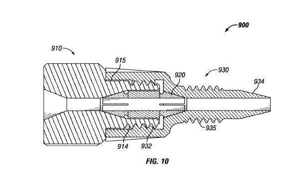
Referring now to FIG. 10, a cross-sectional view of the assembly 900 as shown
in FIG. 9
as connected by an operator is shown. Nut 910, ferrule 920, and fitting 930
are removably
secured to one another. At least a portion of the internal threaded portion
932 of the fitting 930
receives and holds at least a portion of the external threaded portion 914 of
the nut 910. As
noted above, the threaded portions 914 and 932 are each adapted to mate with
each other, such
that a connection can easily be made as shown in FIG. 10. In addition, at
least a portion of the
fitting 930 extends to the exterior portion 915 of the nut 910. The fitting
930 includes an
external threaded portion 935 of the portion of the fitting 930 that extends
outward from the nut
910, as well as a tapered portion 934. The tapered portion 934 of the fitting
930 is adapted to fit
CA 02754544 2011-09-02
WO 2010/102225 PCT/US2010/026387
within a port (not shown) of an LC or other Al component or fitting, and the
threaded portion
935 is adapted to mate with an internally threaded portion (not shown) of the
port of an LC
system component or a fitting or other component of an LC or other Al system.
Now referring to FIG. 11, an alternative embodiment of of an assembly 1100 is
shown.
Like features and elements in the drawings have the same numerals in the
various figures. FIG.
11 provides an exploded cross-sectional view of removable knurl head 1110, nut
1120, ferrule
1130, fitting 1140, and replaceable ferrule tip 1150. Each of removable knurl
head 1110, nut
1120, ferrule 1130, fitting 1140, and replaceable ferrule tip 1150 have
internal passageways
1111, 1121, 1131, 1141, and 1151, respectively, extending therethrough. The
passageways
1111, 1121, 1131, 1141, and 1151 are adapted to allow tubing (not shown) to
extend through
each of removable knurl head 1110, nut 1120, ferrule 1130, fitting 1140, and
replaceable ferrule
tip 1150, and thus through the assembly 1100.
As shown in FIG. 11, removable knurl head 1110 has a first end 1112 and a
second end
1113, and includes an internal portion 1114 at the second end 1113. The
internal portion 1114
of removable knurl head 1110 is adapted to receive first end 1122 of nut 1120
when the
assembly 1100 is connected. Nut 1120 has a first end 1122 and a second end
1123, and includes
an external threaded portion 1124. The threads of the external threaded
portion 1124 of the nut
1120 are adapted to removably receive and securely hold the internal threaded
portion 1144 of
the fitting 1140 when the assembly 1100 is connected.
In FIG. 11, it can be seen that the fitting 1140 has a first end 1142 and a
second
end 1143, and further has an internal tapered portion 1145 near the first end
1142. The
internally tapered portion 1145 of the fitting 1140 is adapted to receive and
removably hold the
second end portion 1133 of the ferrule 1130 when the assembly 1100 is made.
The fitting 1140
further includes an internal threaded portion 1144 near the first end 1142,
and an external
threaded portion 1146 near the second end 1143. Fitting 1140 includes an
internal portion 1147
at the second end 1143. The internal portion 1147 of fitting 1140 is adapted
to receive first end
1152 of ferrule tip 1150 when the assembly 1100 is connected.
With respect to the ferrule 1130 shown in FIG. 11, the ferrule 1130 has a
first end 1132
and a second end 1133 with an external tapered portion 1134. Although not
shown, it will be
appreciated that the angle of tapered portion 1134 of the ferrule 1130 from
the axis of ferrule
1130 may differ from the angles defined by the tapered portion 1145 of the
fitting 1140. For
example, the angle defined by the tapered portion 1134 may be greater than the
angle defined by
21
CA 02754544 2011-09-02
WO 2010/102225 PCT/US2010/026387
tapered portion 1145 to make it easier to obtain sufficient tubing retention
with assembly 1100
when nut 1120, ferrule 1130, and fitting 1140 are engaged and assembled. The
replaceable
ferrule tip 1150 has a first end 1152 and a second end 1153, and an external
tapered portion
1154 at second end 1153.
Referring now to FIG. 12, a cross-sectional view of the assembly 1100 as shown
in FIG.
11 as connected by an operator is shown. Removable knurl head 1110, nut 1120,
ferrule 1130,
fitting 1140, and replaceable ferrule tip 1150 are removably secured to one
another. At least a
portion of the internal threaded portion 1144 of the fitting 1140 receives and
holds at least a
portion of the external threaded portion 1124 of the nut 1120. As noted above,
the threaded
portions 1124 and 1144 are each adapted to mate with each other, such that a
connection can
easily be made as shown in FIG. 12. The fitting 1140 includes an external
threaded portion
1148 of the portion of the fitting 1140 that extends outward from the nut
1120. The tapered
portion 1154 of the replaceable ferrule tip 1150 is adapted to fit within a
port (not shown) of an
LC or other Al component or fitting, and the threaded portion 1148 is adapted
to mate with an
internally threaded portion (not shown) of the port of an LC system component
or a fitting or
other component of an LC or other Al system.
In testing of assemblies like those shown and described herein, good results
have been
obtained. In a first series of tests, assemblies like those shown in FIG. 5
were assembled, in
which the tubing was made of stainless steel, while the nut 10, ferrule 20,
and fitting 30 were
made of PEEK. We used a torque wrench manufactured and available from
Tohnichi,
model 20STC-A, to measure the torque used to connect the test assemblies. In
this first series of
tests, we connected a Haskell test stand, with one side of the tee connected
to a Honeywell
pressure transducer. The other side of the tee was connected to the assembly
being tested. We
filled the assemblies with water and connected the open end of the tubing to a
union that was
plugged. The torque used to connect each of the assemblies was controlled and
measured during
the connection process by the Tohnichi torque wrench. We then pressurized the
assemblies and
measured the pressures withstood before failure was detected. In the first
series of tests,
assemblies like those shown in FIG. 5 were connected with about four inch-
pounds of torque,
and such assemblies withstood a pressure, on average, of over 18,000 psi. In a
second series of
tests, we repeated the procedure described, except that five inch-pounds of
torque were applied
to connect the assemblies. In this second series of tests, the assemblies so
made, like those
shown in FIG. 5, withstood an average pressure of almost 25,000 psi. In still
a third series of
tests, we used the foregoing procedure, except that we tested a series of
assemblies like those
22
CA 02754544 2011-09-02
WO 2010/102225 PCT/US2010/026387
shown in FIG. 8. In this third series of tests, we applied about four inch-
pounds of torque to
connect the assemblies, like those shown in FIG. 8 and found that such
assemblies withstood an
average of over 23,000 psi. Because a human operator can exert forces of four
or five inch-
pounds of torque, an operator can connect the assembly 1 to obtain a leak
proof connection
without the use of tools such as wrenches, pliers or the like, thereby
allowing the operator to
more easily and quickly make or break such connections in UHPLC systems.
Moreover,
because a polymer can be used for ferrule 20 (and ferrule 80 as well), the
assembly 1 is
considered advantageous because there is less chance of deforming the tubing
50 and adversely
affecting the flow rate of fluid through the tubing 50 or affecting the
characteristics of the fluid
flow through tubing 50 (e.g., creating turbulent flow instead of laminar
flow).
While the present invention has been shown and described in various
embodiments,
those skilled in the art will appreciate from the drawings and the foregoing
discussion that
various changes, modifications, and variations may be made without departing
from the spirit
and scope of the invention as set forth in the claims. Hence the embodiments
shown and
described in the drawings and the above discussion are merely illustrative and
do not limit the
scope of the invention as defined in the claims herein. The embodiments and
specific forms,
materials, and the like are merely illustrative and do not limit the scope of
the invention or the
claims herein.
23