Note: Descriptions are shown in the official language in which they were submitted.
CA 02754710 2016-09-09
1
FRICTION BOLT
TECHNICAL FIELD
The present invention relates to a rock bolt for use in rock strata for the
purpose of stabilising the strata against fracture or collapse. The present
invention is concerned principally with friction rock bolts which are known in
the
industry as "split sets" or "friction stabilisers". This form of rock bolt
consists of
a steel tube that is split longitudinally and which is forced into a bore
drilled into
rock strata, so that the external surface of the tube frictionally engages the
internal surface of the bore. Thus, the tube is frictionally anchored within
the
bore.
BACKGROUND TO THE INVENTION
Rock bolts of the above kind are very popular in underground mining sites
throughout the world, because their installation is very simple when compared
to other types of rock bolts. All that is required to install such a rock bolt
is to
drill a bore into the rock strata and then to hammer the rock bolt into the
bore.
In contrast, other forms of rock bolts employ resin or grout to anchor the
rock
bolt within the bore. In respect of resin anchored bolts, a resin cartridge is
usually employed, which is required to be inserted into the bore prior to the
bolt
being inserted therein. Insertion of the resin cartridge is sometimes very
difficult, because typically the tunnel walls extend to a significant height,
so that
access to bores into which the cartridge is to be inserted is inconvenient.
Additionally, the resin which is employed is relatively expensive and has a
limited shelf life.
Cement grouted rock bolts are less expensive than resin anchored bolts, but
application of the cement is more cumbersome than that of the resin. Cement
grouting requires cement mixing equipment, as well as pumping and delivery
equipment, to deliver the mixed cement into the bore.
Despite the installation difficulties of resin and cement anchoring, bolts
anchored in either manner generally are much more efficient in respect of rock
reinforcement or stabilisation, because such bolts have a significantly better
bond between the resin or cement and the bore wall, compared to the frictional
CA 02754710 2016-09-09
2
engagement of a friction rock bolt. Accordingly, it is usually necessary to
employ a greater number of friction rock bolts than compared to resin or
cement grouted bolts, or alternatively, the friction rock bolts are required
to be
longer than resin or cement grouted bolts.
There are other drawbacks associated with the use of friction bolts, such as:
= relatively poor shear strength;
= sensitivity to corrosion; and
= limited ability to support a rock plate against a rock face.
To overcome some of the drawbacks described above, friction bolts are often
post grouted after installation. Advantageously, post grouting increases shear
strength and protects against corrosion. It is also possible to reinforce a
friction rock bolt with a steel bar or cable in addition to post grouting. In
an
installation of this kind, the bar or cable is pushed inside the tube of the
friction
rock bolt immediately after the cement grout has been pumped in. While each
of the above modifications to the traditional friction rock bolt improves the
performance of the bolt, it will be appreciated that they also significantly
add to
the installation time and expense of the rock bolt. For example, post grouting
can be a difficult process, given that typically grout is introduced through a
grout hose, the end of which is fed to the leading end of the rock bolt,
whereafter the hose is withdrawn through the length of the rock bolt as grout
is
pumped into the rock bolt. If withdrawal of the hose is made too quickly,
voids
can form inside the tube. Moreover, if the grout mixture is too thin, then the
grout can flow out of the trailing end of the tube and not fill it.
Additionally, it is
not always apparent to the operator that enough grout has been pumped in to
fill the tube because the existing arrangements do not necessarily provide for
an indication that the tube has been filled. Operator experience is therefore
critical to correct grouting.
It is an object of the present invention to overcome or at least alleviate one
or
more of the drawbacks associated with prior art friction rock bolt
arrangements.
DISCLOSURE OF THE INVENTION
CA 02754710 2016-09-09
3
According to the present invention there is provided a friction bolt, for
frictionally engaging the internal surface of a bore drilled into a rock face,
the
friction bolt comprising an elongate, generally circular tube which is
expandable radially, the tube having a leading end and a trailing end, an
expander mechanism disposed within the tube for applying a load tending to
expand at least a section of the tube radially, an elongate tendon disposed
longitudinally within the tube and in connection at or towards one end of the
tendon with the expander mechanism and in connection at or towards an
opposite end of the tendon with an anchor arrangement, the tendon being
actuatable to expand the expander mechanism and to remain connected
between the expander mechanism and the anchor arrangement while the
expander mechanism is expanded, and an end fitting at the trailing end of the
tube, the end fitting including a central opening through which the tendon
extends, the opening being sized to frictionally engage the outer surface of
the
tendon to resist axial movement of the tendon within the tube and to position
the anchor end of the tendon concentric with the tube, the expander
mechanism comprising a pair of expander elements, a first of which is secured
relative to the tube and a second of which is secured to the elongate tendon,
actuation of the tendon being operable to cause relative movement between
the first and second expander elements to cause the expander mechanism to
expand.
A friction bolt according to the present invention can advantageously enable a
more firm or secure engagement between the friction bolt and the internal
surface of the bore into which the bolt is inserted compared to some other
known rock bolts. Moreover, the inclusion of an elongate tendon within the
tube can increase both the shear and tensile strength of the friction bolt,
particularly if the tendon is a rigid tendon, such as a metal bar, rod or
rigid
cable. Thus, the tendon can be a rigid tendon, such as a metal bar, rod or
rigid
cable, a cable which is not rigid, or it can be a hollow bar.
In addition, because such friction bolts are normally employed with a rock
plate, the arrangement of the present invention can be such that where the
rock supported by the friction bolt fractures and loads the rock plate, the
plate
CA 02754710 2016-09-09
4
can be arranged to cause further actuation of the tendon so that the expander
mechanism is further expanded to increase the frictional engagement between
the tube and the internal surface of the bore. Thus, a friction bolt according
to
the invention can be arranged to increase the frictional engagement between
itself and the internal surface of the bore upon failure or fracture of the
rock
strata, in circumstances in which some prior art friction bolts would be
pulled
either partially or fully from the bore. Thus, a friction bolt according to
the
present invention is expected to provide improved confidence against release
from the bore in circumstances in which the rock strata supported by the
friction bolt fractures or fails.
In a friction bolt according to the invention, the tube can be split
longitudinally,
along at least a portion of its length, but preferably fully along its length.
The
split is provided principally to facilitate radial contraction of the tube so
that the
bore into which the tube is inserted can be drilled to have an internal
diameter
which is slightly less than the external diameter of the tube. In this
arrangement, the friction bolt is forced into the bore, such as by a
percussion
hammer, with the tube contracting radially by closure of the longitudinal
split.
The natural resilience of the tube is such as to cause the tube to
frictionally
engage the bore wall. The external surface of the tube thus engages the bore
wall frictionally upon insertion and prior to any expansion of the expander
mechanism. Expansion of the expander mechanism might result in either no
radial expansion of the tube, or negligible expansion, but rather, the action
of
the expander mechanism is to increase the frictional engagement between the
external surface of the tube and the internal surface of the bore.
The split can also facilitate radial expansion of the tube but that is not
normally
required.
In a friction bolt according to the invention in which the tube includes a
longitudinal split, an elongate, generally circular internal sleeve can be
disposed within the tube and in resting engagement against the internal
surface of the tube. In this arrangement, the internal sleeve bridges or
overlies
the longitudinal split and extends for substantially the length of the split.
CA 02754710 2016-09-09
The internal sleeve can be closed longitudinally, so that it can be circular,
or it
can include an adjustment portion along at least a portion of its length, but
preferably its full length, to allow it to contract and expand radially. That
5 enables the internal sleeve to contract with the tube if the tube is
required to
contract for insertion into a bore, and further enables the sleeve to
thereafter
expand if necessary, when the expander mechanism is actuated to expand.
The expansion portion can be located at the split in the tube.
In the above arrangement, the adjustment portion of the internal sleeve can be
an inwardly extending portion which can be V-shaped. In that arrangement,
the inwardly extending portion can compress or deepen for radial contraction
and can expand or shallow out for radial expansion.
Alternatively, the internal sleeve can be split longitudinally along its
length to
define a longitudinal gap that can open and close with expansion and
contraction of the tube. If this form of internal sleeve is employed, the
split of
the internal sleeve can be offset from the split of the tube (if provided) and
the
respective splits can be approximately diametrically opposed.
It is to be noted that the internal sleeve can be employed with a
longitudinally
closed tube as well as a tube which is longitudinally split. The use of an
internal sleeve with a longitudinally closed tube will provide advantages for
protection of the tendon located within the tube from the effects of water or
moisture penetration. For example, the tube of a friction bolt according to
the
invention can corrode if made out of a corrodible material and if the
corrosion
is such as to penetrate through the full thickness of the tube wall, then the
tendon inside the tube will be exposed to water or moisture from the
surrounding rock strata. Accordingly, the employment of an internal sleeve
can act as a barrier to water and moisture penetration into the interior of
the
tube, despite any serious corrosion that might occur through the thickness of
the tube. It follows that an internal sleeve can be used either with or
without
post grouting as will be described later herein.
CA 02754710 2016-09-09
6
The internal sleeve can be formed of a plastic material, although other
materials could be employed, such as flexible metal sheet, or rubber.
A friction bolt according to the invention can be post grouted and the
employment of a plastic sleeve which bridges or overlies the longitudinal
split
can prevent escape of the grouting medium from within the interior of the
tube,
but still allow for contraction and expansion of the tube as required during
installation of the tube and prior to post grouting. In addition, while the
inclusion of grout can itself protect the tendon from corrosion, the grout
will
usually crack under pressure from the rock strata, so that water or moisture
can access the tendon through the cracks. Thus, the inclusion of a sleeve can
prevent this access.
In an alternative arrangement, the tube of the friction bolt is closed
longitudinally and includes an adjustment portion for at least a portion of
its
length, but preferably fully along its length, so as to permit radial
expansion
and contraction of the tube, as required for insertion of a friction bolt
within a
bore and for any later expansion of the tube under the influence of the
expander mechanism. The adjustment portion can be of the same or similar
kind discussed above in relation to the internal sleeve, so that the
adjustment
portion can comprise an inwardly extending portion which can be formed for
example, in a V-shape so that it can contract or expand during radial
contraction or expansion of the tube.
Where the tube is closed longitudinally, an opening can be provided in the
tube
to facilitate assembly of the expander mechanism within the tube. For
example, the expander mechanism could comprise a pair of wedges, one of
which is fixed to the internal surface of the tube and the other of which is
fixed
to the elongate tendon. Thus, an opening can be provided through the wall of
the tube to enable one of the wedges to be fixed to the tube surface, such as
by welding.
As indicated above, the expander mechanism can comprise a pair of expander
elements, a first of which is secured relative to the tube in any suitable
manner,
CA 02754710 2016-09-09
7
such as welding or by a screw fastener, and a second of which is secured to
the elongate tendon, such as by welding, threaded engagement or other
fastening mechanism such as a barrel and wedge arrangement, or by a pin.
Actuation of the tendon can be such as to cause relative movement between
the first and second expander elements to cause the expander mechanism to
expand. The first and second expander elements can be wedge elements
such that relative linear movement between the elements causes expansion or
contraction, depending on the direction of relative movement.
Other forms of expander mechanisms can be employed as suitable for a rock
bolt according to the present invention.
It is preferred that the expander mechanism be disposed toward the leading
end of the tube, preferably at or very close to the leading end. In a
preferred
arrangement, the leading tip of the tube is tapered to facilitate insertion of
the
friction bolt into a bore, and the expander mechanism is disposed immediately
adjacent to the tapered portion.
In some arrangements, the anchor comprises a nut which is threadably
engaged with the elongate tendon and the anchor further comprises an
abutment against which the nut abuts. The nut can be any suitable form of nut
such as a hex nut or a wing nut. In this arrangement, either of the tendon or
the nut can be rotated relative to the other to actuate the tendon to expand
the
expander mechanism. In one arrangement, it is the nut that is rotated and by
rotation in one direction, the tendon is retracted in a direction away from
the
leading end of the tube to actuate the expander mechanism. Alternatively, the
anchor can be of a barrel and wedge arrangement and actuation of the
expander mechanism is by pulling the tendon through the barrel and wedge
arrangement, with the barrel and wedge arrangement holding the position of
the tendon. This latter arrangement is particularly suited to tendons in the
form
of cables.
In an alternative arrangement, the anchor can comprise a nut which is fixed to
the tendon so that rotation of the nut rotates that tendon. The nut is thus
CA 02754710 2016-09-09
8
employed for engagement by a suitable tool, a spanner or wrench for example,
so that the tendon can be rotated. In this arrangement, rotation of the tendon
actuates the expander mechanism and this can be through threaded
engagement between the tendon and the expander mechanism.
The nut can be fixed to the tendon in any suitable manner, such as by welding
or crimping. Alternatively, a pin can be inserted through the nut and the
tendon, or the nut can be a blind nut. Still further, the nut can be formed
integrally with the tendon, such as by forging.
In an expander mechanism which comprises a pair of wedge elements, the
tendon is connected to one of the wedge elements to move that element
relative to the other of the wedge elements. In an arrangement in which the
anchor comprises a nut which is threadably engaged with the tendon, rotation
of the nut in one direction will retract the tendon which will consequently
retract
one of the wedge elements relative to the other thereby causing expansion of
the expander mechanism. Rotation of the nut in the opposite direction will
cause the expander mechanism to be contracted. By this arrangement, the
expander mechanism can be contracted if the friction bolt is to be removed
from within a bore. This can occur particularly if the friction bolt is
inserted into
a bore which is of greater diameter than the external diameter of the tube of
the bolt. In that arrangement, the bolt frictionally engages the bore wall
only
upon expansion of the expander mechanism to expand the tube, so that
contraction of the expander mechanism contracts the tube and allows the bolt
to be pulled out of the bore.
In an alternative arrangement in which the anchor comprises a nut which is
fixed to the tendon, and the tendon is threadably engaged with a wedge
element of the expander mechanism, the same effect is achieved by rotating
the tendon, which will shift one of the wedge elements relative to the other,
either expanding or contracting the expander mechanism.
It is to be noted that while reference has been made to the expander
mechanism as comprising a pair of wedge elements, it should be appreciated
CA 02754710 2016-09-09
9
that the expander mechanism can comprise elements that are not wedge
elements, for example cam elements, or can comprise an alternative expander
construction.
In addition, while the discussion above has been made in relation to a single
expander mechanism, it is to be appreciated that more than one expander
mechanism could be employed longitudinally within the tube.
Where threaded engagement between the anchor arrangement and the
tendon is employed, or between the expander mechanism and the tendon, the
extent of relative rotation between the tendon and the anchor arrangement and
the expander mechanism can be controlled by limiting the thread length or by
the use of abutments or other suitable barriers, such as deformation of the
tendon.
The abutment of the anchor can be a plate which extends across the trailing
end of the tube. The size of the plate can be such as to overlap the tube end
and in that arrangement, the plate can provide support for a ring which is
fixed
at or adjacent the trailing end of the tube and which is employed to support a
rock plate through which the friction bolt extends. In this arrangement,
advantageously, the support plate can support the ring when the rock plate is
heavily loaded by the rock strata. Thus failure of the ring and thus of the
rock
plate is less likely to occur.
Other abutment arrangements could be employed. For example, the nut or the
barrel and wedge arrangement, could be of a size to abut with the trailing end
of the tube so that the support plate becomes redundant, or the trailing end
of
the tube could be tapered inwardly to a diameter which allows abutment with
the nut or the barrel and wedge arrangement. Still alternatively, the abutment
might be provided by a plug which is fitted into the trailing end of the tube
and
that fitment could involve a friction fit, or threaded fit, or any other
suitable
fitting arrangement. Other suitable forms of anchor are within the scope of
the
invention.
CA 02754710 2016-09-09
In one form of the invention, a tube end fitting is employed which
substantially
closes the trailing end of the tube. Such a fitting could form part of the
anchor
described above, or could be separate from the anchor. In one form of tube
end fitting, the fitting includes a first opening for passage of the elongate
5 tendon and a second opening for passage of a flowable material into the
interior of the tube. The flowable material could be a resin or cement grout
which is pumped into the interior of the tube for the purpose of preventing
compression of the tube under loading from the rock strata. In this
arrangement, the inclusion of an internal sleeve as described above is
10 advantageous to facilitate delivery of the flowable material to the
leading end of
the tube. It does this by forming a passage for the flowable material toward
the
leading end of the tube. A second passage between the bore wall and the
sleeve permits egress of air which is displaced by the flowable material in
the
first passage. The second passage can include the split in the tube as well as
space between the outside of the tube and the bore wall. The inclusion of an
internal sleeve as described above can also minimise escape of resin or
cement grout from within the tube if the tube does include a longitudinal
split.
The use of an end fitting can be such as to provide one of the advantages of
the invention, which is to minimise or eliminate the possibility of grout
flowing
out of the trailing end of the tube when the grout is of a viscosity which is
too
low. In prior art arrangements, the tube end is often open, leaving a large
opening for the grout to flow out of. In this embodiment of the present
invention, the trailing tube end is substantially closed, thereby limiting the
likelihood of escape of grout through that opening.
Moreover, the use of an end fitting with a second opening for passage of
flowable material means that the second opening can be configured to
interface with a grout delivery nozzle or the like and so the need to feed a
grouting hose to the leading end of the rock bolt is eliminated. Moreover,
because grout or resin is pumped into the tube from the trailing end thereof,
the tube will be filled by material flowing towards the leading end, and the
operator of the grout delivery apparatus will receive an indication that the
tube
is filled, either because of an increased back pressure in the delivery
nozzle, or
CA 02754710 2016-09-09
11
if an adjustment portion is provided in the wall of the tube and the internal
sleeve if provided, then grout or resin will flow rearwardly from the leading
end
of the tube in a direction towards the rock plate at the trailing end of the
tube
and the operator will receive a visual indication when the grout or resin
appears at the rock plate. Thus, significantly less operator skill is
necessary
for proper grout delivery to the friction bolt.
The end fitting can be of any suitable material, such as rubber or metal. The
end fitting can cooperate with an anchor arrangement, such as a nut. The end
fitting can comprise two parts, such as a first rubber plug part and a second
metal cover or bell part, the latter of which fits over the rubber end fitting
and
which is engaged by the nut of an anchor. In this latter arrangement, each of
the parts of the end fitting can include openings for passage of the elongate
tendon and for passage of a flowable medium. The two parts of the end fitting
can be arranged to cooperate, such as through threaded engagement or other
connection.
In an end fitting arrangement as discussed above, if an internal sleeve is
employed in the friction bolt, the trailing end of the internal sleeve can be
arranged to seal with the end fitting so as to seal against egress of flowable
material from within the tube. In one arrangement, the end fitting includes a
slot into which the trailing end of the internal sleeve can be received.
Receipt
of the trailing end within the end fitting slot is preferably a snug or tight
fit and
glue can be employed to further enhance the seal between the internal sleeve
and the end fitting.
An alternative use for an end fitting is to properly locate the tendon within
the
tube. A further alternative use for an end fitting is to frictionally engage
the
tendon in a manner which resists movement of the tendon that would cause
the expander mechanism to expand and hinder installation of the friction bolt
into a bore. A single end fitting could be employed for both purposes.
Location of the tendon properly within the tube is expected usually to require
concentric location within the tube. Thus, the end fitting can fit within or
over
CA 02754710 2016-09-09
12
the end of the tube and can include a central opening through which the
tendon can extend. A non-concentric opening can be provided if non-
concentric location of the tendon within the tube is required.
The engagement between the end fitting and the tendon can be loose or a
tight frictional engagement. In some arrangements, an increased frictional
engagement can be employed to provide the benefit of axially locating the
tendon during insertion of a friction bolt into a bore, particularly in cases
in
which the tube of the friction bolt is of greater outer diameter than the
internal
diameter of the bore. In such cases, the tube is required to contract radially
as
it is forced into the bore and for contraction to occur it is important that
the
expander mechanism be disengaged so that the tube can contract. However,
if the tendon is free to move within the tube during installation it may
retract or
shift in a manner to engage the expander mechanism and so prevent or resist
radial contraction of the tube. If frictional engagement of the above kind is
employed, axial movement of the tendon can be resisted or prevented thus
advantageously preventing inadvertent engagement of the expander
mechanism.
If the above frictional engagement between the tendon and the end fitting is
adopted, the frictional load applied to the tendon must not be so high as to
prevent rotation or axial movement of the tendon as may be required for
actuation of the expander mechanism.
The above discussion of the expander mechanism has principally referred to
the use of wedge elements in which one wedge element is shifted relative to
another to expand the mechanism. In this type of expander mechanism, for
most applications, only a small movement of the moveable or "mobile" wedge
element will be required to expand the mechanism. However, in some
applications, particularly in weak rock, the travel of the mobile wedge
element
can be greater and potentially could be large enough that the mobile wedge
element moves completely past the fixed or stationary wedge element. In that
case, the expander mechanism will collapse and provide no expansion load to
the tube and so the benefits of including the expansion mechanism will be
lost.
CA 02754710 2016-09-09
13
Accordingly, the invention provides arrangements to limit travel or movement
of the mobile wedge element to ensure the wedge elements remain proximate
to one another when the expander mechanism is actuated to expand.
In some arrangements where a threaded engagement is employed between
the tendon and a nut of the anchor arrangement, the thread length can be
selected to limit the extent to which the tendon can be retracted to shift the
mobile wedge element. The thread can be terminated to limit tendon
retraction, or an abutment can be employed, such as a pin which extends
through the tendon.
The same arrangement can be applied where the tendon is in threaded
engagement with one of the wedge elements, so that rotation of the tendon is
limited to limit the extent of movement of the wedge element.
The present invention also provides an installation tool for installing a
friction
rock bolt according to the invention and a method of installing a friction
rock
bolt of that kind.
The installation tool includes a socket which is arranged to apply a
percussive
load to the trailing end of a friction bolt according to the invention to
drive the
friction bolt into a bore which has been drilled into a rock wall. The socket
includes an opening for receiving the trailing end of the tendon and a drive
surface about the opening for applying the percussive load. The depth of the
socket opening is sufficient for the drive surface to engage the trailing end
of
the friction bolt without percussively engaging the tendon.
It will be appreciated that the drive surface of the socket can be arranged to
percussively engage any suitable part of the trailing end of the friction
bolt.
Thus, the drive surface could engage a facing surface of the trailing end of
the
tube of the friction bolt, or of an end plate which overlies the tube end, or
any
other suitable friction bolt surface. For example, the drive surface could
engage the facing surface of a nut which is attached or fixed to the trailing
end
of the tendon, so that percussive load could be applied just to the nut, or
CA 02754710 2016-09-09
14
additionally to the nut as well as to another surface or surfaces of the
trailing
end of the friction bolt. In this arrangement, percussive load could be
applied
to the nut and to the trailing end of the tube of the friction bolt or to an
end
plate that overlies the trailing end.
The opening of the socket can be formed to accept the trailing end of the
tendon and, if provided, a nut which is attached to or fixed to the trailing
end of
the tendon. Where a nut is attached to or fixed to the trailing end of the
tendon
the opening can be stepped to have a first portion of a diameter to accept the
trailing end of the tendon and a second portion of a larger diameter to accept
the nut which is attached to or fixed to the trailing end of the tendon. The
nut
can be a square nut or a hex nut or other shaped nut, and the second portion
can have an internal surface complementary to the nut shape.
Between the first and second portions of the opening, a shoulder can be
formed. While that shoulder can be employed to impart a percussive load to a
facing surface of the nut, if such a load is not required, the shoulder can be
positioned so that upon engagement of the drive surface of the socket with the
trailing end of the friction bolt, the shoulder is spaced from engagement with
the nut. Likewise, the inner end of the socket opening can be spaced from the
facing end surface of the tendon upon engagement of the drive surface of the
socket with the trailing end of the friction bolt.
The socket can be arranged to apply a biasing load to the tendon and/or the
nut attached or fixed to the trailing end of the tendon, so that during
percussive
drive of the friction bolt by the socket, the tendon can be maintained in a
position in which the expander mechanism is disengaged so that if necessary,
the tube of the friction bolt can contract radially as it is driven into a
bore of
reduced diameter compared to the outside diameter of the tube. Moreover, the
biasing arrangement can be used to prevent rattling movement of the tendon
during drive of the friction bolt.
The biasing arrangement can comprise a coil spring that acts on the trailing
end of the tendon, such as on the end face of the tendon, or it can be a
rubber
CA 02754710 2016-09-09
or a resilient polymer or the like. The biasing arrangement can also act on
the
inner end of the socket opening. The biasing arrangement can be secured to
the inner end of the socket opening in any suitable manner, such as by a
screw that extends into the socket opening through the side wall of the
socket.
5
The method of installing a friction bolt according to the invention thus
comprises drilling a bore into a rock wall, inserting the leading end of the
friction bolt into the opening of the bore or aligning the leading end of the
friction bolt with the opening of the bore, applying a socket to the trailing
end of
10 the friction bolt, the socket having an opening for receiving the
trailing end of a
tendon of the friction bolt and a drive surface for engaging the trailing end
of
the friction bolt, and driving the socket percussively to drive the friction
bolt into
the bore.
15 The method can involve drilling a bore of an internal diameter which is
less
than the external diameter of the friction bolt tube so that the tube is
forced to
contract as the friction bolt is driven into the bore.
For a better understanding of the invention and to show how it may be
performed, embodiments thereof will now be described, by way of non-limiting
example only, with reference to the accompanying drawings.
BRIEF DESCRIPTION OF THE DRAWINGS
Figure 1 is a sectioned view of a friction rock bolt according to the present
invention.
Figure 1A is a cross-sectional view through AA of Figure 1.
Figure 1B is a cross-sectional view through BB of Figure 1.
Figure 2 is a partially sectioned view of another friction rock bolt according
to
the present invention.
Figure 3 is a cross-sectional view through AA of Figure 2.
CA 02754710 2016-09-09
16
Figure 4 is cross-sectional view through BB of Figure 2.
Figure 5 is a cross-sectional view of the friction rock bolt of Figure 1 as
installed in a bore.
Figure 6 is a cross-sectional view of another friction rock bolt according to
the
present invention.
Figure 7 is a cross-sectional view through BB of Figure 6.
Figure 8 is a cross-sectional view through AA of Figure 6.
Figure 9 is a cross-sectional view of another friction rock bolt according to
the
present invention.
Figure 10 is a cross-sectional view through BB of Figure 8.
Figure 11 is a cross-sectional view of another friction rock bolt according to
the
present invention.
Figure 12 illustrates in part cross-sectional view, the trailing end of the
rock bolt
of Figure 1 with an installation tool attached to the trailing end.
DETAILED DESCRIPTION OF THE DRAWINGS
Figure 1 is a cross-sectional view of a friction rock bolt according to one
embodiment of the invention. The rock bolt 10 includes an elongate generally
circular tube 11 having a leading end 12 and a trailing end 13. The length of
a
typical rock bolt can in the range of about lm to about 5m.
The tube 11 is split longitudinally along its full length. Figure 1A is a
cross-
sectional view of the tube 11 showing the split 21.
CA 02754710 2016-09-09
17
An expander mechanism 14 is disposed within the tube 11 and comprises a
pair of wedge elements 15, 16 which interface along inclined surfaces 17. The
wedge element 16 is fixed to the internal surface 18 of the tube 11 at the
leading end 12 of the tube 11 by welding, while the wedge element 15 is
secured by threaded engagement to the leading end of an elongate tendon 19.
The tendon 19 can be a rigid metal rod or bar, or it can be a cable. It will
be
easily understood, that relative movement between the wedge elements 15
and 16 will result in either contraction or expansion of the expander
mechanism 14, depending on the direction of relative movement. Movement
of the wedge element 15 in a direction toward the trailing end 13 of the tube
11
will result in expansion of the expander mechanism 14.
The leading end 12 of the tube 11 is tapered to facilitate insertion of the
rock
bolt 10 into a bore drilled into a rock face. The end 12 includes two slits on
opposite sides thereof, however only one slit 20 is visible in Figure 1. The
slits
facilitate compression of the leading end 12 if necessary for insertion into
the
bore.
The tendon 19 extends beyond the trailing end 13 of the tube 11 and includes
threaded ends 21 and 22. A hex nut 23 is fixed to the tendon 19 adjacent the
threaded end 22.
The nut 23 is fixed to the tendon 19 so that rotation of the nut 23 rotates
the
tendon 19. The nut 23 can be fixed to the tendon 19 by crimping or welding or
any other suitable fixing arrangement.
Rotation of the nut 23 rotates the tendon 19 so that the wedge element 15
shifts axially on the threaded end 21. Sufficient axial shifting of the wedge
element 15 will bring the inclined surfaces 17 together and will impose an
expansion load against the internal surface 18 of the tube 11.
The nut 23 is one part of an anchor, which also comprises an abutment in the
form of an end plate 24. The end plate 24 overlies the open trailing end 13 of
the tube 11 and extends in proximity to a ring 25 which is welded to the outer
CA 02754710 2016-09-09
18
surface 26 of the tube 11. When installed, the ring 25 abuts against a rock
plate (not shown) to secure the rock plate against a rock wall surface and
when the rock bolt is under heavy load, the end plate 24 provides additional
support to the ring 25 to resist the load applied to the rock plate. Thus the
ring
25 is supported against failure by the end plate 24.
The rock bolt 10 further includes an end fitting 27 which is formed as a plug
or
bush which is fitted into the open trailing end 13 of the bolt 10. The end
fitting
27 can be a plastic or rubber bush and is intended to be a friction fit
against
the internal surface 18 of the tube 11. The end fitting 27 includes a central
opening through which the tendon 19 extends and the size of the opening is
intended to generate a friction fit against the external surface of the tendon
19.
The function of the end fitting 27 is two-fold. Firstly, the end fitting 27
maintains the anchor end of the tendon 19 concentric with the tube 11. Thus,
the tube 11 is restricted against lateral or radial movement relative to the
tube
11. The concentric location of the tendon 19 also maintains the end plate 24
concentrically located across the open trailing end 13 of the tube 11 so that
the
end plate 24 maintains its position extending across the open trailing end 13
of
the tube 11 for support of the ring 25.
In addition, the end fitting 27 frictionally engages the tendon 19 so that
axial
movement of the tendon 19 is resisted during insertion of the rock bolt 10
into
a bore. This is important to ensure that the tendon 19 does not move axially
in
the direction toward the trailing end 13 resulting in engagement between the
wedge elements 15 and 16 and preventing radial contraction of the tube 11 as
it is inserted into a bore. As explained above, often rock bolts are inserted
into
a bore which has an internal diameter less than the external diameter of the
bolt, so that the outer diameter of the bolt must contract to allow insertion
of
the rock bolt into the bore. By maintaining the tendon 19 in the position
shown
in Figure 1, the wedge elements are maintained spaced apart and the tube 11
can contract where the bolt 10 is inserted into a bore of reduced diameter.
CA 02754710 2016-09-09
19
The advantage of the end fitting 27 is that it is a simple and inexpensive
component, but it provides significant advantages in the operation of the bolt
10.
With reference to Figure lb, a cross sectional view through section B-B is
illustrated, which shows the end fitting 27 in frictional engagement with both
the tube 11 and the tendon 19.
It is to be noted that the threaded end 22 of the tendon 19 extends beyond the
nut 23 and that is provided for the attachment of auxiliary rock support such
as
wire mesh. Such wire mesh can extend between adjacent bolts and is
provided to capture rock fragments which are dislodged from a rock wall,
rather than allowing the fragments to fall as falling rock can present a
danger
to workers working proximate the rock wall.
While the rock bolt 10 of Figure 1 is not shown as including an internal
sleeve,
such a sleeve could be included if considered appropriate. The addition of an
internal sleeve, such as that shown by reference numeral 51 in Figures 5 to 7,
or reference numeral 71 in Figures 8 and 9 in the rock bolt 10 can present a
barrier to the ingress of water into the interior of the tube 11, so as to
protect
the tendon 19 against water or moisture.
The rock bolt 10 provides various advantages over prior art bolts as
previously
indicated herein, but in particular, the rock bolt 10 provides efficient
anchoring
of the leading end 12 within a bore, while the shear and tensile strength of
the
bolt is increased by the inclusion of the tendon 19. Additionally, the
attachment of the tendon to the expander mechanism significantly improves
the tensile strength of the friction bolt and to a lesser extent the shear
strength,
compared to prior art bolts in which a rod is simply inserted into the
interior of
the tube after grout has been introduced. Advantages provided by the addition
of the end plate 24 have been discussed above.
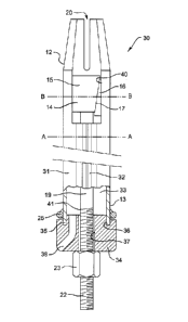
Figure 2 is a part side and part cross-sectional view of a rock bolt 30
according
to another embodiment of the invention. Figure 3 is a cross-section taken
CA 02754710 2016-09-09
through the rock bolt 30 through A-A, while Figure 4 is a cross-section taken
through the rock bolt 30 through B-B. The rock bolt 30 includes many of the
features of the rock bolt 10 of Figure 1, and therefore the same reference
numerals have been employed to identify the same features.
5
The rock bolt 30 includes an elongate tube 31 which is closed longitudinally
as
shown in the cross-sectional view in Figures 3 and 4. The tube 31 includes an
adjustment portion 32 which is formed as an inwardly extending generally V-
shaped portion. While the adjustment portion 32 can extend for only a portion
10 of the length of the tube 31, the preference is that it extends fully
along the
length. It will be evident to a person skilled in the art, that upon expansion
radially of the tube 31, the adjustment portion 32 will expand and will
shallow
out, whilst when the tube 31 is contracted, the adjustment portion 32 will
contract and will deepen.
In the rock bolt 30, an alternative arrangement is provided for engagement of
the expander mechanism 14. In the rock bolt 10, the nut 23 is fixed to the
tendon 19, so that upon rotation of the nut 23, the tendon 19 is also rotated.
That rotation was relative to the wedge element 15 which is threadably
connected to the tendon 19, so that upon rotation of the tendon 19, the wedge
element 15 was caused to move axially within the tube.
In contrast, in Figure 2, the nut 23 is threaded to the tendon 19, while the
wedge element 14 is fixed to the tendon 19. In this arrangement, rotation of
the nut 23 is relative to the tendon 19 and causes axial movement of the
tendon 19. With that axial movement, the wedge element 14 also moves
axially.
In each of the rock bolts 10 and 30, a control mechanism is provided to ensure
that axial movement of the wedge element 15 towards the trailing end 13 of the
bolt is not so great as to completely pass the fixed wedge element 16. With
reference to Figure 1, the shoulder 28 of the tendon 19 represents the
maximum travel of the wedge element 14 along the tendon 19. Accordingly,
when the bottom end 29 of the wedge element 15 engages the shoulder 28, no
CA 02754710 2016-09-09
21
further axial movement of the wedge element 15 towards the trailing end 13
can take place. Accordingly, even though further expansion of the tube 11
might be available, the expander mechanism 14 will not produce further
expansion load.
In respect of the rock bolt 30, the threaded end 22 extends to a non-threaded
portion 41 at which point the minor diameter of the threaded portion 22 is
smaller than the outside diameter of the portion 41. By this arrangement,
when the nut 23 reaches the portion 41, the nut 23 cannot rotate any further
and therefore further axial movement of the tendon 19 is terminated.
Figure 5 shows the rock bolt 10 of Figure 1 in an installed condition within a
bore 42 in a body of rock 43. A rock plate 44 is secured between the ring 25
of
the bolt 10 and the rock face 45, while it can be seen that the wedge elements
15 and 16 of the expander mechanism 14 have been shifted relative to each
other so that the inclined surfaces 17 of the respective elements 15 and 16
are
in engagement. It will be evident from Figure 5, that the nut 23 has not
shifted
relative to the tendon 19, but rather, rotation of the nut 23 has rotated the
tendon 19 and that has shifted the wedge element 15 on the threaded end 21.
Thus, the wedge element 15 has shifted downwardly in the view of Figure 5
relative to the fixed wedge element 16 so that a radial expansion load has
been applied to the internal surface 18 of the tube 11.
It will further be evident, that the bottom edge 29 of the wedge element 15
has
reached the shoulder 28 of the tendon 19, at the end of the threaded end 21,
so that no further movement of the wedge element 15 on the tendon 19 is
available. By this mechanism, the wedge element 15 is able to move only to
the position in Figure 5 and no further. Thus, the mechanism provides that the
wedge elements 15 and 16 always remain in engagement and prevents the
wedge element 15 from moving past the wedge element 16 in the direction of
the trailing end 13 of the bolt.
In a rock bolt 30 of Figure 2, post grouting of the bolt can be achieved by
pumping grout into the interior 33 of the tube 31. To facilitate insertion of
grout
CA 02754710 2016-09-09
22
into the interior 33, the rock bolt 30 includes an end fitting 34 which is
fitted
over the trailing end of the tube 31 by the tube end 35 fitting into a slot 36
formed in the end fitting 34. The tube end 35 can fit into the slot 36 by
frictional engagement, or a threaded or other suitable engagement can be
provided.
The fitting 34 can locate the tendon 19 concentrically within the tube 11 at
the
trailing end 13 and can frictionally engage the tendon 19 for the reasons
explained in respect of the end fitting 27 of Figure 1.
The fitting 34 includes a first opening 37 to receive the trailing end of the
tendon 19 and a second opening 38 for delivery of grout. A suitable grout
delivery device can be employed to interface with the opening 38 for the
passage of grout therethrough.
The benefit of post grouting of the rock bolt 30 is that the cured grout
resists
compression of the tube 31 which tends to occur when the bolt is under the
influence of a load that causes the bolt to be pulled out of the bore in which
it
has been inserted. The method of installation if post grouting is employed is
that the bolt 30 is inserted into a bore drilled into the rock strata and
thereafter
the expander mechanism 13 is activated by rotation of the nut 23 to retract
the
tendon 19 in a direction towards the trailing end 13 of the tube 31. Once the
expander mechanism 14 has been expanded as desired, grout can be pumped
into the interior of the tube 31. Once the grout has reached the leading end
12
of the rock bolt 30, the grout can travel toward the trailing end 13 though
the
adjustment portion 32. That return portion of grout can bond with the wall of
the bore into which the rock bolt 30 has been inserted, to increase the hold
of
the bolt 30 within the bore. Additionally, upon the grout appearing at the
trailing end of the rock bolt 30, the operator of the grout delivery device
will
have visual confirmation of proper grouting of the bolt 30.
Figure 4 illustrates in cross-section through B-B, how the expander mechanism
14 is accommodated within the tube 31 which is formed with the adjustment
portion 32. It can be seen that the wedge elements 15 and 16 are sized and
CA 02754710 2016-09-09
23
shaped to be accommodated within the interior of the tube 31, inboard of the
innermost end of the expansion portion 32. Additionally, Figure 4 illustrates
an
opening 39 through which a weld can be applied to the rear surface of the
wedge element 16 to fix that surface to the interior surface of the tube 31.
Alternatively, an opening 40 (see Figure 2), can be made in the wall of the
tube
31 to provide access for fixing of the wedge element 16, such as by welding
the wedge element 16 at opposite ends as shown in Figure 1. Either of the
opening arrangements shown in Figure 2 or 4 can be adopted, as can be
alternative arrangements not illustrated.
Figure 6 is a cross-sectional view of a rock bolt 50 according to another
embodiment of the invention. The rock bolt 50 differs from the earlier rock
bolts 10 and 30, by the inclusion of an interior sleeve 51. Again, features
which are common to the rock bolts 10 and 30 maintain the same reference
numerals in Figure 1.
The rock bolt 50 includes a tube 52 and a longitudinal split 53 (see Figure
7).
The split 53 extends for the full length of the tube 52 and permits the tube
52 to
radially expand and contract.
The interior sleeve 51 is generally circular, but includes an adjustment
portion
54 which is formed as an inwardly extending generally V-shaped portion. The
profile of the interior sleeve 51 is similar to the profile of the closed tube
31 of
the rock bolt 30 shown in Figure 2, therefore the interior sleeve 51 overlies
or
bridges the split 53 in the tube 52.
The interior sleeve 51 advantageously assists to protect the tendon 19 from
corrosion, by preventing access to the tendon, or at least restricting access,
to
exposure to water or moisture. It will be appreciated from Figure 6, that the
full
length of the rock bolt 50 is not shown, and it is to be appreciated that only
a
small portion of the overall length of the tube 52 does not include the
interior
sleeve 51. Thus, it is the major portion of the tendon 19 which is protected
from exposure to water or moisture by the interior sleeve 51.
CA 02754710 2016-09-09
24
Moreover, because the interior sleeve 52 bridges the split 53, cement grout
which is pumped into the interior of the rock bolt 50 is substantially
prevented
from escaping through the split 53. It is the grout which provides the
principle
protection to the tendon 19 against exposure to water or moisture, while the
grout also assists to properly anchor the friction bolt within a bore.
The interior sleeve 51 is preferably of plastic, although any sufficiently
flexible
material is acceptable provided the adjustment portion 54 of the sleeve 51 can
expand and contract with the tube 52 as required.
The rock bolt 50 further includes a tube end fitting for substantially closing
the
trailing end 13 of the tube 52 and the end fitting illustrated in Figure 6 is
a two-
part fitting, which comprises a first plug part 55 and a second cover part 56.
Figure 8 illustrates a cross-sectional view taken through A-A of Figure 6. As
shown in Figures 6 and 8, the plug 55 includes three openings 57 for the
passage of grout, and a central opening 58 to accommodate passage of the
tendon 19. The plug 55 is shown to be a close fit to the interior sleeve 51
and
in the preferred arrangement, the fit is a friction fit so that the plug 55
seals
against the interior sleeve 51.
The cover 56 interconnects with the plug 55 by the flange 59 being received
within a complementary slot in the cover 56 and the cover 56 is attached to
the
tube end 60 via a step 61. By this arrangement, the cover 56 is centralised on
the tube 11, which assists centralisation of the tendon 19. The cover 56 is
preferably made from a metallic material.
The cover 56 includes an opening 62 to receive the nozzle of a grout supply
device so that grout which is pumped through the opening 62 flows through the
openings 57 of the plug 55 and into the interior of the bolt 50.
In other respects, the rock bolts 30 and 50 operate in a similar manner to the
rock bolt 10 of Figure 1, in that the respective rock bolts 30, 50 are
inserted
into a bore and the expander mechanism 14 is actuated by rotation of the nut
23 relative to the tendon 19. That nut rotation draws the tendon 19 in a
CA 02754710 2016-09-09
direction toward the trailing end 13 of the respective bolts 30, 50 to cause
the
expander mechanism to expand and for the tube 52 to firmly grip the interior
wall of the bore. Thereafter, grout can be inserted through the respective
openings 38 and 62 and left to cure.
5
Figure 9 illustrates a further embodiment of a rock bolt according to the
invention. The rock bolt 70 of Figure 9 is very similar in construction to the
rock bolt 50 of Figure 6, in that the rock bolt 70 includes an interior sleeve
71.
Like earlier figures, like parts are given the same reference numerals.
The rock bolt 70 includes an elongate tube 72 which has a longitudinal split
73
(Figure 10). The rock bolt 70 further includes an end fitting 74 which is
similar
to the end fitting 34 of the rock bolt 30, however in the arrangement of
Figure
9, the interior sleeve 71 includes a tapered or flared end 75 that extends
into a
slot 76 formed in the end fitting 74 in order for the sleeve 71 to seal within
the
end fitting 74. To improve the seal, an adhesive may be employed within the
slot 76.
In other respects, the construction of the rock bolt 70 is similar to the rock
bolt
30 of Figure 2 in that a single part end fitting 74 is provided and grout is
pumped through an opening 77 in the end fitting 74 into the interior of the
tube
72. The method of insertion and expansion of the expander mechanism 14 is
again the same as that described in relation to the rock bolts 30 and 50.
In relation to the introduction of cement grout into the interior of the tube,
the
grout delivery apparatus can include a cup that interfaces with the grout bell
of
the figures, rather than employing a nozzle. The cup will deliver grout to
feed
into the interior of the tube through the opening in the grout bell, for
example
the openings 38, 62 or 77 of Figures 2, 6 and 9.
Figure 11 illustrates a further friction rock bolt 80 which in most respects
is very
similar to the rock bolt 10 of Figure 1. Accordingly, for like parts, the same
reference numerals have been employed. Where the rock bolt 80 differs from
the rock bolt 10, is in respect of the tendon 81, which is in the form of a
cable
CA 02754710 2016-09-09
26
rather than a metal rod or bar, and also in respect of the anchor 82 which is
in
the form of a barrel and wedges anchor, rather than a anchor of the kind
shown in the earlier figures. The anchor 82 thus comprises a barrel 83 and a
plurality of wedges 84, through which the cable 81 extends. Engagement of
the wedge elements 15 and 16 is by retracting the tendon 81 in the direction
of
the trailing end 13 of the bolt 80, while return movement of the cable 81 is
resisted by engagement of the wedges 84 in the barrel 83.
Figure 12 illustrates in part cross-sectional view, the trailing end of the
rock bolt
10 of Figure 1, with the end fitting 27 omitted, so that Figure 12 illustrates
a
tube 11, a ring 25 and an end plate 24. Further illustrated is the threaded
end
22 of the tendon 19 (obscured), and the nut 23 which is fixed to the tendon
19.
Figure 12 further illustrates the socket 90 of an installation tool the
remaining
components of which are not illustrated. The installation tool, through the
socket 90, is arranged to apply a percussive load to the trailing end of the
rock
bolt 10 in order to insert the rock bolt 10 into a bore which has been drilled
into
a rock wall. The socket 90 includes an opening 91 which accommodates the
threaded end 22 of tendon 19 and the hex nut 23. The opening 91 includes a
first portion 92 of a first diameter which is sized to accommodate the
trailing
end 22, and a hexagonal second portion 93 of a larger diameter which is sized
to accommodate the nut 23. A shoulder 94 is formed at the junction between
the first and second portions 92 and 93.
The socket 90 further includes a drive surface 95, which is a hexagonal
surface that completely surrounds the nut 23. The drive surface 95 is intended
to apply a percussive drive load to the facing surface of the end plate 24 in
order to drive the rock bolt 10 into a bore which has been drilled in a rock
wall.
In the Figure 12 illustration, the drive surface 95 is intended to provide the
only
contact with the rock bolt 10 for driving of the bolt into a bore. Thus, the
space
between the drive surface 95 and the facing surface of the end plate 24 is
required to be smaller than the space between the shoulder 94 and the facing
surface of the nut 23. In addition, the inner end 96 of the opening 92 is
CA 02754710 2016-09-09
27
required to be spaced from the facing end 97 of the threaded end 22. By that
arrangement, when the socket 90 is driven percussively, the only drive contact
between the socket 90 and the rock bolt 10 is between the drive surface 95
and the facing surface of the end plate 24.
Disposed within the opening 92 is a coil spring 98, although it is expected
that
in practice, the spring 98 will be a rubber or resilient polymer block or
part.
The spring is fixed to the inner end 96 of the socket 90 in any suitable
manner
such as by a screw (not shown) that extends through the wall of the socket,
and the opposite end of the spring 98 engages against the facing end 97 of the
threaded end 22. By this arrangement, the spring 98 applies a biasing load to
the threaded end 22 so that the nut 23 remains in contact with the end plate
24
during drive of the rock bolt 10 into a hole. Advantageously, by this
arrangement, the tendon 19 is retained in a position in which the expander
mechanism is disengaged, so that resistance to radial contraction of the tube
11 of the rock bolt 10 is eliminated as the rock bolt is inserted into a bore.
The
biasing influence provided by the spring 98 is also effective to prevent the
tendon 19 from rattling during installation of the rock bolt 10.
The arrangement illustrated in Figure 12 advantageously reduces loss of
energy during drive of a rock bolt into a hole by directly applying the drive
to
the end plate 24, rather than through the threaded end 22 or the nut 23.
It will be appreciated however, that if drive of the rock bolt 10 is required
through engagement not only between the drive surface 95 and the end plate
24, but also between the shoulder 94 and the nut 23, that the dimensions of
the socket 90 can be altered so that simultaneous engagement is provided.
The invention described herein is susceptible to variations, modifications
and/or additions other than those specifically described and it is to be
understood that the invention includes all such variations, modifications
and/or
additions which fall within the spirit and scope of the above description.